EP1077348A1 - Gasbeheizter Wärmestrahler - Google Patents
Gasbeheizter Wärmestrahler Download PDFInfo
- Publication number
- EP1077348A1 EP1077348A1 EP00121839A EP00121839A EP1077348A1 EP 1077348 A1 EP1077348 A1 EP 1077348A1 EP 00121839 A EP00121839 A EP 00121839A EP 00121839 A EP00121839 A EP 00121839A EP 1077348 A1 EP1077348 A1 EP 1077348A1
- Authority
- EP
- European Patent Office
- Prior art keywords
- hood
- burner
- converter
- heating gases
- radiant heater
- Prior art date
- Legal status (The legal status is an assumption and is not a legal conclusion. Google has not performed a legal analysis and makes no representation as to the accuracy of the status listed.)
- Granted
Links
- 239000007789 gas Substances 0.000 claims abstract description 46
- 238000010438 heat treatment Methods 0.000 claims abstract description 35
- 230000005855 radiation Effects 0.000 claims abstract description 26
- 238000009413 insulation Methods 0.000 claims abstract description 4
- 239000004020 conductor Substances 0.000 abstract 1
- 239000000567 combustion gas Substances 0.000 description 7
- 238000002485 combustion reaction Methods 0.000 description 5
- 239000000919 ceramic Substances 0.000 description 3
- 238000010521 absorption reaction Methods 0.000 description 2
- 238000012423 maintenance Methods 0.000 description 2
- 229910000831 Steel Inorganic materials 0.000 description 1
- 239000011358 absorbing material Substances 0.000 description 1
- 238000000137 annealing Methods 0.000 description 1
- 238000004140 cleaning Methods 0.000 description 1
- 230000000694 effects Effects 0.000 description 1
- 230000005611 electricity Effects 0.000 description 1
- 238000005265 energy consumption Methods 0.000 description 1
- 239000000446 fuel Substances 0.000 description 1
- 230000003760 hair shine Effects 0.000 description 1
- 239000011810 insulating material Substances 0.000 description 1
- 238000004519 manufacturing process Methods 0.000 description 1
- 239000002184 metal Substances 0.000 description 1
- 239000011819 refractory material Substances 0.000 description 1
- 239000010959 steel Substances 0.000 description 1
Images

Classifications
-
- F—MECHANICAL ENGINEERING; LIGHTING; HEATING; WEAPONS; BLASTING
- F24—HEATING; RANGES; VENTILATING
- F24C—DOMESTIC STOVES OR RANGES ; DETAILS OF DOMESTIC STOVES OR RANGES, OF GENERAL APPLICATION
- F24C3/00—Stoves or ranges for gaseous fuels
- F24C3/04—Stoves or ranges for gaseous fuels with heat produced wholly or partly by a radiant body, e.g. by a perforated plate
- F24C3/042—Stoves
-
- F—MECHANICAL ENGINEERING; LIGHTING; HEATING; WEAPONS; BLASTING
- F23—COMBUSTION APPARATUS; COMBUSTION PROCESSES
- F23D—BURNERS
- F23D14/00—Burners for combustion of a gas, e.g. of a gas stored under pressure as a liquid
- F23D14/12—Radiant burners
- F23D14/125—Radiant burners heating a wall surface to incandescence
-
- F—MECHANICAL ENGINEERING; LIGHTING; HEATING; WEAPONS; BLASTING
- F23—COMBUSTION APPARATUS; COMBUSTION PROCESSES
- F23D—BURNERS
- F23D14/00—Burners for combustion of a gas, e.g. of a gas stored under pressure as a liquid
- F23D14/12—Radiant burners
- F23D14/151—Radiant burners with radiation intensifying means other than screens or perforated plates
Definitions
- the invention relates to a gas-heated heat radiator, the Can be used as a ceiling spotlight for heating halls is.
- incandescent lamps in the form of incandescent lamps and in are known Form of dark spots.
- incandescent lamps is one Ceramic plate provided the numerous continuous Has openings in which supplied gas is burned, wherein the ceramic plate is heated to the annealing temperature and Radiates heat. This results in high Radiation temperatures, so that incandescent lamps usually in greater height can be used.
- US Pat. No. 4,727,854 describes a gas-heated heat radiator, where the heating gases generated by a burner be passed through a radiation tube, which in a hood open at the bottom is arranged.
- the radiation pipe is heated up by the heating gases and then shines heat from the outside.
- the radiation tube forms one Converter, the heat exchange surface along which the heating gases flow, the inner tube wall is while the heat radiation to the outside through the pipe outer wall.
- the invention has for its object a gas-heated To create radiant heaters with low energy consumption generates a high heat output.
- the converter is which absorbs the convection heat of the combustion gases and in Radiant heat, a body with opposite to the effective radiation area enlarged surface on which sweep the combustion gases.
- the needed Temperature (approx. 300 ° C) of the converter is not caused by high Speeds of the heating gases reached, but by a greatly enlarged surface on which the heating gases sweep along and which is thereby heated convectively.
- the Partial surfaces of this surface shine on each other. Because the externally effective radiation area of the converter is a lot is smaller than the heat exchange surface, the heats up Converter to the required temperature.
- the effective one The radiation area of the converter is in the radiation direction projected area.
- the heat radiator according to the invention can be used as an economical dark radiator be designated. With him the heating or Combustion gases along a converter structure greatly enlarged surface. By the big one Ratio of heat exchange area to radiation area achieved that the heating gases are relatively slow at the converter can flow along. This is the heat exchange improved. Gas combustion can be considered atmospheric Combustion takes place where a forced draft burner does not is required. Because of the even distribution of the gases the gas consumption is low. The converter can do this be dimensioned so that the highest efficiency is achieved that is permissible. It is also advantageous that the Radiant heater has a low weight, which is particularly the case with the mounting of the heat radiator on a hall roof by Meaning is. All components are easily accessible, so that maintenance is made easier.
- Another advantage is that the converter from the Heating gases can be flowed through in the transverse direction and thus is heated evenly at all points. This gives uniform radiation intensity over the entire Radiant area.
- the Converter arranged in a hood open at the bottom, below which direct the combustion gases from the burner.
- the hood forms an inverted lake, the absorbs the combustion gases and on the converter leads along.
- the combustion gases pass along one Edge under the hood, flow through the hood in Transverse direction, along the converter and leave the hood on the opposite edge.
- a gas and heat exchange also takes place in Longitudinal direction of the hood instead.
- the hood adjusts one structure open below, through the opening of which the converter is easily accessible for cleaning or maintenance purposes.
- This hood can be a reflective surface and / or a Have radiation area.
- a radiant area ideally acts as a black body, i.e. it absorbs incident radiation and emits its own radiation from.
- the burner can be on the one edge of the hood as a separate Device be attached. It contains a longitudinal one Fuel tube, which is preferably only part of the Combustion chamber length extends.
- the outlet slot of the combustion chamber is shaped so that the heating gases extend over the length of the Outlet slot distributed substantially evenly from the Exit the combustion chamber. This means that the Flow resistance of the outlet slot in the length range of Burner tube is larger than in those length ranges, in which the burner tube is not available.
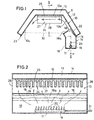
- the heat radiator has an elongated hood 10 which designed as an inverted U-shaped trough open at the bottom is and can have a length of several meters.
- the hood 10 is e.g. made of metal and here it has a horizontal extending base plate 10a, which is inclined downwards and connect outside side plates 10b and 10c.
- the hood could also have an edgeless round structure or one have a different polygon structure.
- the hood 10 is on hers Provide the top with thermal insulation 11, e.g. out can consist of a layer of heat-insulating material.
- thermal insulation 11 from an auxiliary hood 12 placed on the hood 10 forms a heat-insulating air space 13.
- This burner 15 has an elongated Burner chamber 16 on the bottom with Air inlet openings 17 is provided and on its top a slot-shaped elongated outlet opening 18 for which has heating gases.
- a horizontal burner tube 19 on its top has numerous gas outlet openings 20 which in are arranged at regular intervals.
- the burner tube 19 is supplied from an external gas line 21 gas that from the gas outlet openings 20 exits and mixed with the outside air burns so that over the gas outlet openings 20 atmospherically burning flames are created.
- the burner tube 19 extends only over a partial area the length of the hood 10, here about the middle third. So that the heating gases are evenly distributed over the Entire length of the burner chamber 16 from the outlet 18th emerge is in the middle of the length of the Burner chamber 16 is a sheet narrowing the outlet opening 18 18a provided a throttling effect in this area exercises while the other areas of the outlet opening 18th are unthrottled.
- the Baffle 22 extends over the outlet openings 20 and parallel to the side plate 10b of the hood 10. The outlet opening 18 is directed so that those emerging from it Heating gases on the side plate 10b of the hood 10 sweep along.
- the heating gases that have left the burner chamber 16 rise under the hood 10 and flow on the hood wall along to after releasing a significant portion of their heat flow out under the opposite edge 23.
- the heating gases can, for example, directly into the Environment. You can also use a Chimney (not shown) can be removed.
- the converter 24 is located under the base plate 10a of the hood attached. This converter 24 extends over the entire length of the hood 10. It contains a base plate 25, from which numerous parallel ribs 26 project downwards, so that the converter here - seen in front view - is comb-shaped. Extend between the ribs 26 downwardly open guide channels 27 which are transverse to Longitudinal direction of the hood 10 run. On the front The hood 10 ends by end walls 28 and 29, respectively completed.
- the heating gases flow after leaving the burner chamber 16 along the converter 24 and through the guide channels 27 through it. They heat the converter 24, the for example made of steel or ceramic. Because of the Ribs 26, converter 24 has a very large surface area, which is in heat exchange with the heating gases. To this The converter heats itself up even when it is slower Flow rate of the heating gases very strongly. On the other hand, the converter 24 gives off radiant heat from. The effective radiation area of the converter 24 is in the essentially through the vertical projection of the converter is much smaller than that Heat exchange surface. After the converter 24 has heated up a thermal equilibrium is created between the absorbed convection heat and the emitted Radiant heat, the converter having a temperature of e.g. Assumes 300 ° C. After the heating gases heat the converter 24 have left, they leave the hood at a temperature of about 150 ° C.
- a wind protection grille 30 arranged over the entire hood opening extends and prevents drafts from reaching the converter 24 arrives and cools it down.
- the windscreen 30 serves also the increase in efficiency.
- the parts of the hood 10, in particular the side plates 10b and 10c, can be designed as reflectors to reflect on to reflect them on striking heat radiation and thus to be directed diagonally into the space below the hood 10. In this way, a wide radiation pattern be achieved.
- parts of the Manufacture hood from radiation absorbing material that Absorbs radiant heat and acts as an internal radiator.
- the downwardly open hood 10 causes a flow of the Heating gases along the guide channels 27 of the converter 24.
- Die Hood forms a kind of thermosiphon in which the heating gases first ascend and down after releasing their heat be derived.
- the converter 24 is in the present Embodiment designed so that the guide channels 27th just passed. It can also be designed as a labyrinth be in which the heating gases have a meandering shape Pass through the flow path.
- the burner 15 is here at the top of the Hood arranged and releases the heating gases from its bottom 15a exit into the hood.
- the converter 24a is arranged, which here as down open (reverse) gutter is formed parallel to the burner 15 runs.
- the converter 24a is smooth here Walls, however the walls could also be structured his.
- the converter 24a has an essentially trapezoidal shape.
- the Walls of the converter 24a have a surface that the area of the opening 32 is much larger.
- the area 32 forms the projection of the surface of the converter 24a. she is much smaller than the area of the converter.
- the outflow of the heating gases from the burner 15 is in Fig. 3 designated 33.
- the heating gases that burn the burner 15 have left, flow into the converter 24a on one side into it, flow diagonally upwards and back again below, in order to then exit under the edge of the hood 10.
- the hood is the same as in the first embodiment 10 elongated and the burner 15 and the converter 24a run as elongated components in the longitudinal direction of the Hood.
- the converter is in this embodiment in Flows through the transverse direction.
Landscapes
- Engineering & Computer Science (AREA)
- Chemical & Material Sciences (AREA)
- Combustion & Propulsion (AREA)
- Mechanical Engineering (AREA)
- General Engineering & Computer Science (AREA)
- Gas Burners (AREA)
- Resistance Heating (AREA)
- Control And Other Processes For Unpacking Of Materials (AREA)
- Waste-Gas Treatment And Other Accessory Devices For Furnaces (AREA)
Abstract
Description
- Fig. 1
- einen Querschnitt durch eine erste Ausführungsform des Wärmestrahlers,
- Fig. 2
- einen Längsschnitt entlang der Linie II-II von Fig. 1 und
- Fig. 3
- einen Längsschnitt durch eine nicht zur Erfindung gehörende Ausführungsform des Wärmestrahlers.
Claims (11)
- Gasbeheizter Wärmestrahler mit einem Brenner (15), dessen Heizgase an einem Konverter (24) entlanggeführt werden, welcher Strahlungswärme an die Umgebung abstrahlt, wobei der Konverter (24;24a) ein Körper mit gegenüber der wirksamen Strahlungsfläche vergrößerter Oberfläche ist, bei dem die den Heizgasen ausgesetzte Wärmeaustauschfläche mindestens doppelt so groß ist - vorzugsweise mindestens viermal so groß ist - wie die wirksame Strahlungsfläche,
dadurch gekennzeichnet,
dass der Konverter (24,24a) aus einer länglichen, nach unten offenen Rinne oder mehreren nach unten offenen Leitkanälen (27) besteht, die von den Heizgasen durchströmt sind. - Wärmestrahler nach Anspruch 1, dadurch gekennzeichnet, daß der Konverter (24) in einer nach unten offenen Haube (10) angeordnet ist, unter die die Heizgase des Brenners (15) geleitet werden.
- Wärmestrahler nach Anspruch 2, dadurch gekennzeichnet, daß der Brenner (15) eine Brennerkammer (16) aufweist, die längs des einen Randes (14) der langgestreckten Haube (10) verläuft, derart, daß die Heizgase die Haube (10) quer zu deren Längsrichtung durchströmen und am gegenüberliegenden Rand (23) abströmen.
- Wärmestrahler nach Anspruch 2, dadurch gekennzeichnet, daß der Brenner (15) an einem Ende der langgestreckten Haube (10) angeordnet ist, wobei die Heizgase die Haube (10) in Längsrichtung durchströmen.
- Wärmestrahler nach einem der Ansprüche 2 bis 4, dadurch gekennzeichnet, daß die Haube (10) an ihrer Außenseite eine Wärmedämmung (11) aufweist.
- Wärmestrahler nach einem der Ansprüche 2 bis 5, dadurch gekennzeichnet, daß die Innenseite der Haube (10) mindestens abschnittsweise als Reflektorfläche ausgebildet ist.
- Wärmestrahler nach einem der Ansprüche 2 bis 6, dadurch gekennzeichnet, daß die Innenseite der Haube (10) mindestens abschnittsweise als Strahlungsfläche ausgebildet ist.
- Wärmestrahler nach einem der Ansprüche 1 bis 7, dadurch gekennzeichnet, daß der Brenner (15) ein sich in einer Brennerkammer (16) erstreckendes Brennerrohr (19) mit Gasaustrittsöffnungen (20) aufweist, dessen Länge kürzer ist als die Brennerkammer (16) und daß die Brennerkammer (16) einen Auslaß (18) aufweist, dessen Breite im Längenbereich des Brennerrohres (19) verringert ist.
- Wärmestrahler nach einem der Ansprüche 1 bis 8, dadurch gekennzeichnet, daß an der Öffnung der Haube (10) ein Windschutzgitter (30) vorgesehen ist.
- Wärmestrahler nach einem der Ansprüche 1 bis 9, dadurch gekennzeichnet, daß der Konverter (24) nach unten offene Leitkanäle (27) aufweist, die ganz oder abschnittsweise quer zur Längsrichtung der Haube (10) verlaufen.
- Wärmestrahler nach Anspruch 10, dadurch gekennzeichnet, daß der Konverter (24) aus einer Rippenstruktur mit nach unten weisenden Rippen (26) besteht, wobei die Heizgase parallel zu den Rippen an diesen entlangstreichen.
Applications Claiming Priority (3)
| Application Number | Priority Date | Filing Date | Title |
|---|---|---|---|
| DE29516643U | 1995-10-21 | ||
| DE29516643U DE29516643U1 (de) | 1995-10-21 | 1995-10-21 | Gasbeheizter Wärmestrahler |
| EP96116842A EP0769658B1 (de) | 1995-10-21 | 1996-10-19 | Gasbeheizter Wärmestrahler |
Related Parent Applications (1)
| Application Number | Title | Priority Date | Filing Date |
|---|---|---|---|
| EP96116842A Division EP0769658B1 (de) | 1995-10-21 | 1996-10-19 | Gasbeheizter Wärmestrahler |
Publications (2)
| Publication Number | Publication Date |
|---|---|
| EP1077348A1 true EP1077348A1 (de) | 2001-02-21 |
| EP1077348B1 EP1077348B1 (de) | 2003-09-17 |
Family
ID=8014395
Family Applications (2)
| Application Number | Title | Priority Date | Filing Date |
|---|---|---|---|
| EP00121839A Expired - Lifetime EP1077348B1 (de) | 1995-10-21 | 1996-10-19 | Gasbeheizter Wärmestrahler |
| EP96116842A Expired - Lifetime EP0769658B1 (de) | 1995-10-21 | 1996-10-19 | Gasbeheizter Wärmestrahler |
Family Applications After (1)
| Application Number | Title | Priority Date | Filing Date |
|---|---|---|---|
| EP96116842A Expired - Lifetime EP0769658B1 (de) | 1995-10-21 | 1996-10-19 | Gasbeheizter Wärmestrahler |
Country Status (3)
| Country | Link |
|---|---|
| EP (2) | EP1077348B1 (de) |
| AT (2) | ATE250202T1 (de) |
| DE (3) | DE29516643U1 (de) |
Cited By (2)
| Publication number | Priority date | Publication date | Assignee | Title |
|---|---|---|---|---|
| WO2004090424A3 (en) * | 2003-04-01 | 2004-12-23 | Radiant Optics Inc | Radiant energy source systems, devices and methods |
| US7116900B2 (en) | 2003-04-01 | 2006-10-03 | Radiant Optics, Inc. | Radiant energy source systems, devices, and methods capturing, controlling, or recycling gas flows |
Citations (5)
| Publication number | Priority date | Publication date | Assignee | Title |
|---|---|---|---|---|
| US4432727A (en) * | 1982-09-21 | 1984-02-21 | Joseph Fraioli | Gas-fired infrared projection heater |
| US4507083A (en) * | 1982-09-21 | 1985-03-26 | Joseph Fraioli | Gas-fired infrared projection heater |
| US4702693A (en) * | 1986-12-03 | 1987-10-27 | Joseph Fraioli | Gas-fired infrared heater |
| US4727854A (en) * | 1986-05-08 | 1988-03-01 | Johnson Arthur C W | High efficiency infrared radiant energy heating system and reflector therefor |
| DE3903540A1 (de) * | 1989-02-07 | 1990-08-09 | Guenter Petz | Heizstrahler |
Family Cites Families (6)
| Publication number | Priority date | Publication date | Assignee | Title |
|---|---|---|---|---|
| DE7309345U (de) * | 1973-09-20 | Jenewein & Gapp Gmbh | Gaskaminofen | |
| FR2190249A5 (de) * | 1972-06-22 | 1974-01-25 | Utilisation Ration Gaz | |
| US3763847A (en) * | 1972-09-07 | 1973-10-09 | Foster Miller Ass | Radiant heater |
| DE2706043C2 (de) * | 1977-02-12 | 1982-09-16 | Herbert 4050 Mönchengladbach Baumanns | Strahlungsbrenner |
| DE3415058A1 (de) * | 1984-04-21 | 1985-10-31 | GoGas Goch GmbH & Co, 4600 Dortmund | Strahlungsbrenner |
| FR2654806B1 (fr) * | 1989-11-17 | 1992-02-14 | Triatherm Sarl | Appareil de chauffage au gaz par rayonnement infrarouge. |
-
1995
- 1995-10-21 DE DE29516643U patent/DE29516643U1/de not_active Expired - Lifetime
-
1996
- 1996-10-19 DE DE59610724T patent/DE59610724D1/de not_active Expired - Lifetime
- 1996-10-19 AT AT00121839T patent/ATE250202T1/de not_active IP Right Cessation
- 1996-10-19 EP EP00121839A patent/EP1077348B1/de not_active Expired - Lifetime
- 1996-10-19 AT AT96116842T patent/ATE200567T1/de not_active IP Right Cessation
- 1996-10-19 DE DE59606754T patent/DE59606754D1/de not_active Expired - Lifetime
- 1996-10-19 EP EP96116842A patent/EP0769658B1/de not_active Expired - Lifetime
Patent Citations (5)
| Publication number | Priority date | Publication date | Assignee | Title |
|---|---|---|---|---|
| US4432727A (en) * | 1982-09-21 | 1984-02-21 | Joseph Fraioli | Gas-fired infrared projection heater |
| US4507083A (en) * | 1982-09-21 | 1985-03-26 | Joseph Fraioli | Gas-fired infrared projection heater |
| US4727854A (en) * | 1986-05-08 | 1988-03-01 | Johnson Arthur C W | High efficiency infrared radiant energy heating system and reflector therefor |
| US4702693A (en) * | 1986-12-03 | 1987-10-27 | Joseph Fraioli | Gas-fired infrared heater |
| DE3903540A1 (de) * | 1989-02-07 | 1990-08-09 | Guenter Petz | Heizstrahler |
Cited By (3)
| Publication number | Priority date | Publication date | Assignee | Title |
|---|---|---|---|---|
| WO2004090424A3 (en) * | 2003-04-01 | 2004-12-23 | Radiant Optics Inc | Radiant energy source systems, devices and methods |
| US6932079B2 (en) | 2003-04-01 | 2005-08-23 | Radiant Optics | Radiant energy source systems, devices, and methods capturing, controlling, or recycling gas flows |
| US7116900B2 (en) | 2003-04-01 | 2006-10-03 | Radiant Optics, Inc. | Radiant energy source systems, devices, and methods capturing, controlling, or recycling gas flows |
Also Published As
| Publication number | Publication date |
|---|---|
| ATE200567T1 (de) | 2001-04-15 |
| DE29516643U1 (de) | 1997-02-20 |
| EP0769658B1 (de) | 2001-04-11 |
| EP1077348B1 (de) | 2003-09-17 |
| EP0769658A1 (de) | 1997-04-23 |
| DE59606754D1 (de) | 2001-05-17 |
| DE59610724D1 (de) | 2003-10-23 |
| ATE250202T1 (de) | 2003-10-15 |
Similar Documents
| Publication | Publication Date | Title |
|---|---|---|
| DE69200573T2 (de) | Heizung mit katalytischem Brenner. | |
| DE3147993C2 (de) | Metall-Glühofen | |
| DE3710244A1 (de) | Brenner, insbesondere gasbrenner, brennerrost aus solchen brennern und wasserheizer mit solchen brennern | |
| DE4207500C2 (de) | Heizkessel mit verringerter NO¶x¶-Emission | |
| EP1077348B1 (de) | Gasbeheizter Wärmestrahler | |
| DE1905148B2 (de) | Strahlungsbrenner | |
| AT409892B (de) | Heizeinrichtung für feste brennstoffe, insbesondere kompaktofen bzw. kamineinsatz | |
| DE3018794C2 (de) | Gasherd mit einer wärmeübertragenden Platte und einem Strahlungsbrenner | |
| DE2363006A1 (de) | Elektrischer heizofen | |
| DE3418977A1 (de) | Strahlungsbrenner | |
| DE3014937C2 (de) | Gasherd mit einem Strahlungsbrenner und einer das Kochfeld bildende Platte | |
| DE4223799C2 (de) | Gasheizgerät | |
| DE2403127A1 (de) | Radiatorheizkoerper | |
| DE2812962C2 (de) | Heizofen für Holz | |
| AT404873B (de) | Zuluftleitvorrichtung für die sekundärluft einer heizeinrichtung | |
| EP0917633A1 (de) | Gasbrenner | |
| CH691508A5 (de) | Zuluftverteilungseinrichtung für die Verbrennungsluft von Heizeinrichtungen, insbesondere für Festbrennstoffe sowie Verfahren zum Zuführen von Verbrennungsluft. | |
| DE102004044194A1 (de) | Doppelgitter | |
| DE10155226B4 (de) | Heizgerät mit einem Brenner mit Porenkörper | |
| DE9419506U1 (de) | Wärmespeicherofen | |
| DE4430860A1 (de) | Strahlungsheizkörper | |
| DE19941895A1 (de) | Gasherd zum Grillen von Speisen | |
| DE3509887C2 (de) | ||
| AT346539B (de) | Ofen mit eingebautem gasbrenner | |
| DE1753168C (de) | Mit natürlichem Zug arbeitendes Strahlungsheizgerät |
Legal Events
| Date | Code | Title | Description |
|---|---|---|---|
| PUAI | Public reference made under article 153(3) epc to a published international application that has entered the european phase |
Free format text: ORIGINAL CODE: 0009012 |
|
| 17P | Request for examination filed |
Effective date: 20001006 |
|
| AC | Divisional application: reference to earlier application |
Ref document number: 769658 Country of ref document: EP |
|
| AK | Designated contracting states |
Kind code of ref document: A1 Designated state(s): AT BE CH DE DK FR GB LI NL SE |
|
| AKX | Designation fees paid |
Free format text: AT BE CH DE DK FR GB LI NL SE |
|
| 17Q | First examination report despatched |
Effective date: 20021104 |
|
| GRAH | Despatch of communication of intention to grant a patent |
Free format text: ORIGINAL CODE: EPIDOS IGRA |
|
| GRAS | Grant fee paid |
Free format text: ORIGINAL CODE: EPIDOSNIGR3 |
|
| GRAA | (expected) grant |
Free format text: ORIGINAL CODE: 0009210 |
|
| AC | Divisional application: reference to earlier application |
Ref document number: 0769658 Country of ref document: EP Kind code of ref document: P |
|
| AK | Designated contracting states |
Kind code of ref document: B1 Designated state(s): AT BE CH DE DK FR GB LI NL SE |
|
| REG | Reference to a national code |
Ref country code: GB Ref legal event code: FG4D Free format text: NOT ENGLISH |
|
| REG | Reference to a national code |
Ref country code: CH Ref legal event code: EP Ref country code: CH Ref legal event code: NV Representative=s name: ING. MARCO ZARDI C/O M. ZARDI & CO. S.A. |
|
| REF | Corresponds to: |
Ref document number: 59610724 Country of ref document: DE Date of ref document: 20031023 Kind code of ref document: P |
|
| PG25 | Lapsed in a contracting state [announced via postgrant information from national office to epo] |
Ref country code: SE Free format text: LAPSE BECAUSE OF FAILURE TO SUBMIT A TRANSLATION OF THE DESCRIPTION OR TO PAY THE FEE WITHIN THE PRESCRIBED TIME-LIMIT Effective date: 20031217 Ref country code: DK Free format text: LAPSE BECAUSE OF FAILURE TO SUBMIT A TRANSLATION OF THE DESCRIPTION OR TO PAY THE FEE WITHIN THE PRESCRIBED TIME-LIMIT Effective date: 20031217 |
|
| GBT | Gb: translation of ep patent filed (gb section 77(6)(a)/1977) |
Effective date: 20040113 |
|
| ET | Fr: translation filed | ||
| PLBE | No opposition filed within time limit |
Free format text: ORIGINAL CODE: 0009261 |
|
| STAA | Information on the status of an ep patent application or granted ep patent |
Free format text: STATUS: NO OPPOSITION FILED WITHIN TIME LIMIT |
|
| 26N | No opposition filed |
Effective date: 20040618 |
|
| REG | Reference to a national code |
Ref country code: CH Ref legal event code: PCAR Free format text: ISLER & PEDRAZZINI AG;POSTFACH 1772;8027 ZUERICH (CH) |
|
| PGFP | Annual fee paid to national office [announced via postgrant information from national office to epo] |
Ref country code: NL Payment date: 20081023 Year of fee payment: 13 |
|
| PGFP | Annual fee paid to national office [announced via postgrant information from national office to epo] |
Ref country code: CH Payment date: 20081027 Year of fee payment: 13 |
|
| PGFP | Annual fee paid to national office [announced via postgrant information from national office to epo] |
Ref country code: AT Payment date: 20081023 Year of fee payment: 13 |
|
| PGFP | Annual fee paid to national office [announced via postgrant information from national office to epo] |
Ref country code: BE Payment date: 20081024 Year of fee payment: 13 |
|
| BERE | Be: lapsed |
Owner name: *BAUMANNS HERBERT Effective date: 20091031 |
|
| REG | Reference to a national code |
Ref country code: NL Ref legal event code: V1 Effective date: 20100501 |
|
| REG | Reference to a national code |
Ref country code: CH Ref legal event code: PL |
|
| PG25 | Lapsed in a contracting state [announced via postgrant information from national office to epo] |
Ref country code: NL Free format text: LAPSE BECAUSE OF NON-PAYMENT OF DUE FEES Effective date: 20100501 |
|
| PG25 | Lapsed in a contracting state [announced via postgrant information from national office to epo] |
Ref country code: AT Free format text: LAPSE BECAUSE OF NON-PAYMENT OF DUE FEES Effective date: 20091019 |
|
| PG25 | Lapsed in a contracting state [announced via postgrant information from national office to epo] |
Ref country code: BE Free format text: LAPSE BECAUSE OF NON-PAYMENT OF DUE FEES Effective date: 20091031 Ref country code: CH Free format text: LAPSE BECAUSE OF NON-PAYMENT OF DUE FEES Effective date: 20091031 Ref country code: LI Free format text: LAPSE BECAUSE OF NON-PAYMENT OF DUE FEES Effective date: 20091031 |
|
| PGFP | Annual fee paid to national office [announced via postgrant information from national office to epo] |
Ref country code: FR Payment date: 20121113 Year of fee payment: 17 |
|
| PGFP | Annual fee paid to national office [announced via postgrant information from national office to epo] |
Ref country code: GB Payment date: 20121023 Year of fee payment: 17 |
|
| GBPC | Gb: european patent ceased through non-payment of renewal fee |
Effective date: 20131019 |
|
| PG25 | Lapsed in a contracting state [announced via postgrant information from national office to epo] |
Ref country code: GB Free format text: LAPSE BECAUSE OF NON-PAYMENT OF DUE FEES Effective date: 20131019 |
|
| REG | Reference to a national code |
Ref country code: FR Ref legal event code: ST Effective date: 20140630 |
|
| PG25 | Lapsed in a contracting state [announced via postgrant information from national office to epo] |
Ref country code: FR Free format text: LAPSE BECAUSE OF NON-PAYMENT OF DUE FEES Effective date: 20131031 |
|
| PGFP | Annual fee paid to national office [announced via postgrant information from national office to epo] |
Ref country code: DE Payment date: 20141204 Year of fee payment: 19 |
|
| REG | Reference to a national code |
Ref country code: DE Ref legal event code: R119 Ref document number: 59610724 Country of ref document: DE |
|
| PG25 | Lapsed in a contracting state [announced via postgrant information from national office to epo] |
Ref country code: DE Free format text: LAPSE BECAUSE OF NON-PAYMENT OF DUE FEES Effective date: 20160503 |