EP1077351B1 - Elektrisches Steuergerät für einen Heizkörper, insbesondere einen elektrischen Handtuchtrockner - Google Patents
Elektrisches Steuergerät für einen Heizkörper, insbesondere einen elektrischen Handtuchtrockner Download PDFInfo
- Publication number
- EP1077351B1 EP1077351B1 EP99440227A EP99440227A EP1077351B1 EP 1077351 B1 EP1077351 B1 EP 1077351B1 EP 99440227 A EP99440227 A EP 99440227A EP 99440227 A EP99440227 A EP 99440227A EP 1077351 B1 EP1077351 B1 EP 1077351B1
- Authority
- EP
- European Patent Office
- Prior art keywords
- electrical
- heating member
- heating
- actuator
- electrical actuator
- Prior art date
- Legal status (The legal status is an assumption and is not a legal conclusion. Google has not performed a legal analysis and makes no representation as to the accuracy of the status listed.)
- Expired - Lifetime
Links
- 238000010438 heat treatment Methods 0.000 claims description 52
- 230000002093 peripheral effect Effects 0.000 claims description 4
- 230000005540 biological transmission Effects 0.000 claims 1
- 238000009434 installation Methods 0.000 description 6
- 239000013529 heat transfer fluid Substances 0.000 description 3
- 238000007654 immersion Methods 0.000 description 3
- 238000004519 manufacturing process Methods 0.000 description 3
- 230000010354 integration Effects 0.000 description 2
- 238000007726 management method Methods 0.000 description 2
- 208000031968 Cadaver Diseases 0.000 description 1
- 230000006978 adaptation Effects 0.000 description 1
- 230000000712 assembly Effects 0.000 description 1
- 238000000429 assembly Methods 0.000 description 1
- 230000006866 deterioration Effects 0.000 description 1
- 238000000034 method Methods 0.000 description 1
- 230000000149 penetrating effect Effects 0.000 description 1
- 230000001681 protective effect Effects 0.000 description 1
- 238000007789 sealing Methods 0.000 description 1
- 238000004804 winding Methods 0.000 description 1
Images

Classifications
-
- F—MECHANICAL ENGINEERING; LIGHTING; HEATING; WEAPONS; BLASTING
- F24—HEATING; RANGES; VENTILATING
- F24H—FLUID HEATERS, e.g. WATER OR AIR HEATERS, HAVING HEAT-GENERATING MEANS, e.g. HEAT PUMPS, IN GENERAL
- F24H9/00—Details
- F24H9/18—Arrangement or mounting of grates or heating means
- F24H9/1854—Arrangement or mounting of grates or heating means for air heaters
- F24H9/1863—Arrangement or mounting of electric heating means
-
- F—MECHANICAL ENGINEERING; LIGHTING; HEATING; WEAPONS; BLASTING
- F24—HEATING; RANGES; VENTILATING
- F24H—FLUID HEATERS, e.g. WATER OR AIR HEATERS, HAVING HEAT-GENERATING MEANS, e.g. HEAT PUMPS, IN GENERAL
- F24H9/00—Details
- F24H9/20—Arrangement or mounting of control or safety devices
- F24H9/2007—Arrangement or mounting of control or safety devices for water heaters
- F24H9/2014—Arrangement or mounting of control or safety devices for water heaters using electrical energy supply
-
- F—MECHANICAL ENGINEERING; LIGHTING; HEATING; WEAPONS; BLASTING
- F24—HEATING; RANGES; VENTILATING
- F24H—FLUID HEATERS, e.g. WATER OR AIR HEATERS, HAVING HEAT-GENERATING MEANS, e.g. HEAT PUMPS, IN GENERAL
- F24H3/00—Air heaters
- F24H3/002—Air heaters using electric energy supply
- F24H3/004—Air heaters using electric energy supply with a closed circuit for a heat transfer liquid
Definitions
- the present invention relates to the field of equipment domestic, in particular of heating and more particularly the towel radiators, and relates to an electrical device for controlling a radiator, in particular an electric towel radiator.
- the towel radiators are radiators. often used as auxiliary radiators, consisting of a body heater on which towels or the like can be hung and by a device for controlling and adjusting a penetrating heating means tightly in said body, such as an immersion heater.
- the body heater is usually filled with a heat transfer fluid and closed with sealingly at the immersion heater.
- radiators are produced in the form of a complete assembly, namely radiator and control device, in factory, and are installed directly by qualified operators.
- the control device which can be of the control type to distance, contains all the circuits necessary for this purpose and present in the form of a relatively complex and bulky element, this which entails risks of deterioration during storage, transport and handling before and during installation. Furthermore, this device also requires a relatively complex and front connection necessarily be carried out by qualified personnel.
- the heating body of these assemblies has a wired outlet which requires a connection to the control circuit and this connection is made in the factory. As a result, for power installations different, it is necessary to carry out the manufacture of as many sets corresponding, so that the references are multiplied and the stocks which increases the cost of the heating thus produced.
- this control device is equipped with a actuation by infrared and this receiver must be precisely positioned towards the command transmitter in order to guarantee optimal operation.
- a radiator electric comprising an electric control device connected to said radiator, at the end of the heating element.
- this device electric control is connected to the heating element in one position predetermined and is housed in a protective casing without possibility subsequent orientation for adaptation according to positioning of a remote control means to be accessible.
- the object of the present invention is to overcome these drawbacks by proposing an electrical device for controlling a radiator, particular of an electric towel heater, allowing a control, in particular from a distance, of a radiator by simple means and quick installation.
- the electric device for controlling a radiator is constituted by an electrical control means a heating device integrated in a heating element and by a quick adjustment means in position of said control means relative to the heating element, this quick adjustment means being constituted by a connection piece by snap cooperating with a connection and orientation ring, fitted to the corresponding end of the heating element, by snap-fastening in the outlet end of the heater.
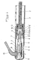
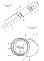
- FIGS. 1 to 3 of the accompanying drawings show a device electric control of a radiator, in particular a radiator electric towel warmer.
- this device is constituted by an electrical means 1 for controlling a heater 2 integrated in a heating element 3 and by means 4 of adjustment fast in position of said control means 1 relative to the element heater 3, this quick adjustment means 4 being constituted by a snap-on connection nozzle 12 cooperating with a connection and orientation ring 3, fitted to the corresponding end of the heating element 3, by snap-fastening in the end of outlet from the heating body.
- the heating element 3 is not shown, in Figures 1 to 3 of attached drawings, only by a cooperating radiator end element with the heating device 2.
- This heating device 2 is present, in the embodiment shown in the accompanying drawings, in the form of a immersion heater immersed in a heat transfer fluid. However, it could also be envisaged to produce this heating device 2 in the form a solenoid valve connected to a central heating circuit.
- the electrical means 1 for controlling the heating device 2 advantageously takes the form of an electric actuator 5, connected electrically to the heater 2 and energized via a means 6 of direct or indirect actuation.
- Electric actuator 5 is advantageously constituted in the form of a relay provided with an output wired connected to a plug-in connector 7 on corresponding tabs 8 of the heating body 2.
- the means 6 of direct or indirect actuation of the actuator electric 5 can be either in the form of a device electromechanical such as a switch connected to the relay forming the actuator electric 5, either in the form of an infrared or radio frequency receiver connected to said relay forming the actuator 5.
- All of the electrical control means 1 is connected known manner to a power cord 19 to be connected to the installation electric.
- This electrical control means 1 is further constituted by a body 9 for receiving the electric actuator 5 and the means 6 actuating the latter, this body 9 being provided, on the one hand, with a orifice 10 for passage of the power cord 19 and an opening 11 for housing of the direct or indirect actuation means 6 of the actuator electric 5 and, on the other hand, a snap-on connection end piece 12 cooperating with a connection ring 13 and orientation fitted the corresponding end of the heating element 3 by snapping into the outlet end of the heating body 2.
- the snap-on connection end piece 12 is integral with the end of the body 9 and is advantageously provided with at least one elastic tongue 12 'which cooperates, in the mounting position of the body 9 on the heating element 3, with an annular rib 14 provided on the end corresponding to the heating body 2, a peripheral seal 15 housed in a groove in said end of the heating body 2 ensuring sealing with the body 9.
- connection ring 13 ( Figures 1 and 3) is provided with a part, of elastic snap tabs 13 'cooperating with a rib internal annular 16 of the corresponding end of the heating body 2 and, on the other hand, at its opposite end, 13 "peripheral grooves cooperating, in the mounting position of the body 9, with ribs of positioning 17 arranged in parallel on the internal wall of the body 9 ( Figures 1 and 4).
- Such rotation with indexing in position by cooperation of the 13 "grooves with the ribs of positioning 17 provides precise adjustment of the position of the means 6 for direct or indirect actuation of the electric actuator 5 by in relation to the heating element 3, in view, either of its easy access for a manual control, i.e. positioning of the receiving cell by relative to an element emitting infrared waves or radio frequencies.
- the body 9 is further provided with internal ribs 18 arranged symmetrically by relative to its longitudinal axis and intended to produce guide rails, positioning and holding the actuator actuation means 6 electric 5, as well as the latter.
- Such an embodiment of the body 9 allows perform a complete assembly of the actuating means assembly 6 and electric actuator 5, as well as the power cord 19 in a sub-assembly control module, of which only connector 7, connected to the actuator electric 5 by means of connection wires, remains mobile and accessible for mounting on the corresponding end of the body heats 2 of a heating element 3.
- this wired connection allows a significant relative movement between the body 9 and the heating body 2, because that the available length of wire allows a fairly large winding of these on themselves.
- the electric actuator 5 and the means 6 of control of the electric actuator 5 can also be carried out under form of two independent circuits, the actuator 5 being, for example, under form of a power circuit, while the control means 6 is supplied with low voltage.
- the control means 6 it is possible to envisage the integration of the relay of tensioning of the body 2 or solenoid valve directly in a sleeve corresponding to the heating element 3, the control means 6 being limited to simple low voltage control of the energizing relay heater body voltage 2.
- the constitution and the method of mounting the device in accordance with the invention allow not only a quick connection of it to a heating element 3, but also easy access, before mounting the device, to the heating body 2, which becomes easily removable. So, it can perfectly be envisaged to carry out the storage and the delivery of heating elements 3 vacuum, filling with heat transfer fluid can be carried out directly on site before installation.
- the invention it is possible to produce a device electric control of a radiator, in particular a radiator electric towel warmer simple to manufacture and quick to assemble simple.
- this device in the form of a sub-assembly can simply and quickly be connected to a body of heater allows significant gains both in terms of manufacturing logistics, the subset obtained can easily be adapted to different heaters and at different powers.
- the device according to the invention allows, in the case of an order to distance, to optimize the range of the means used.
- the device according to the invention can be produced under the shape of an aesthetic subset of small footprint.
- This device has essentially been described for use with electric heaters. However, it is entirely possible integrate the device according to the invention with heating radiators central, whose individual management is ensured through a centralized circuit of the home automation type.
Landscapes
- Engineering & Computer Science (AREA)
- Physics & Mathematics (AREA)
- Thermal Sciences (AREA)
- Chemical & Material Sciences (AREA)
- Combustion & Propulsion (AREA)
- Mechanical Engineering (AREA)
- General Engineering & Computer Science (AREA)
- Central Heating Systems (AREA)
Claims (10)
- Elektrische Betriebs- und Steuervorrichtung eines Heizkörpers, insbesondere eines Hand-tuchtrockners,
dadurch gekennzeichnet, dass sie durch eine elektrische Betriebs- und Steuereinrichtung (1) einer Heizvorrichtung (2), die in ein heizendes Bauteil (3) integriert ist, und durch eine Einrichtung (4) zum schnellen Einstellen der Position der genannten Betriebs- und Steuereinrichtung (1) in Bezug auf das heizende Bauteil (3) gebildet ist, wobei diese Einrichtung (4) zum schnellen Einstellen der Position durch ein mit einem Verbindungs- und Einstellring (13) zusammenwirkendes Schnappkupplungsteil (12) gebildet ist, das das entsprechende Ende des heizenden Bauteils (3) durch Einschnappen in dem Ausgangsende des Körpers der Heizeinrichtung (2) installiert. - Vorrichtung nach Anspruch 1,
dadurch gekennzeichnet, dass die Betriebs- und Steuereinrichtung (1) der Heizvorrichtung (2) in Form einer elektrischen Wirkeinheit (5) vorliegt, die mit der Heizeinrichtung (2) elektrisch verbunden ist und mittels eines Betätigungsorgans (6) mittelbar oder unmittelbar unter Spannung gesetzt ist. - Vorrichtung nach Anspruch 2,
dadurch gekennzeichnet, dass die elektrische Wirkeinheit (5) in Form eines Relais' gebildet ist, das mit einem Anschluß versehen ist, der mit einem Verbindungsteil (7) verbunden ist, das auf entsprechende Laschen (8) der Heizeinrichtung (2) aufsteckbar ist. - Vorrichtung nach Anspruch 2,
dadurch gekennzeichnet, dass das mittelbare oder unmittelbare Betätigungsorgan (6) der elektrischen Wirkeinheit (5) in Form einer elektromechanischen Vorrichtung, wie eines mit dem die elektrische Wirkeinheit (5) bildenden Relais' verbundenen Schalters, oder eines Infrarotwellen-empfängers oder Radiofrequenzwellenempfängers, der mit dem genannten die Wirkeinheit (5) bildenden Relais verbunden ist, vorliegt. - Vorrichtung nach Anspruch 1 oder 2,
dadurch gekennzeichnet, dass die Betriebs- und Steuereinrichtung (1) außerdem durch ein Gehäuse (9) zur Aufnahme der elektrischen Wirkeinheit (5) und des Betätigungsorgans (6) dieser letzteren gebildet ist, wobei dieses Gehäuse (9) mit einer Durchlassöffnung (10) des Versorgungskabels (19) und mit einer Öffnung (11) des Sitzes des unmittelbaren oder mittelbaren Betätigungsorgans (6) der elektrischen Wirkeinheit (5) versehen ist. - Vorrichtung nach Anspruch 5,
dadurch gekennzeichnet, dass das Schnappkupplungsteil (12) fest verbunden mit dem Ende des Gehäuses (9) ist und mit wenigstens einer elastischen Zunge (12') versehen ist, die in der an das heizende Bauteil (3) angesetzten Stellung des Gehäuses (9) mit einer ringförmigen Rippe (14) zusammenwirkt, die an dem entsprechenden Ende des Körpers der Heizvorrichtung (2) vorgesehen ist, wobei eine in einer Rille des genannten Endes des Körpers der Heizvorrichtung (2) sitzende Umfangsdichtung (15) die Dichtheit mit dem Gehäuse (9) sicherstellt. - Vorrichtung nach Anspruch 5,
dadurch gekennzeichnet, dass der Verbindungs- und Einstellring (13) einerseits mit elastischen Rastkrallen (13') versehen ist, die mit einer ringförmigen Innenrippe (16) des entsprechenden Endes des Körpers der Heizvorrichtung (2) zusammenwirken, und andererseits, an seinem entgegengesetzten Ende, mit umfangsseitigen Rillen (13") versehen ist, die in der montierten Stellung des Gehäuses (9) mit Positionierrippen (17) zusammenwirken, die parallel an der Innenwand des Gehäuses (9) angeordnet sind. - Vorrichtung nach Anspruch 5,
dadurch gekennzeichnet, dass das Gehäuse (9) außerdem mit Innenrippen (18) versehen ist, die, bezogen auf seine Längsachse, symmetrisch angeordnet sind und bestimmt sind, Führungs-, Positionierungs- und Halterungsschienen des Betätigungsorgans (6) der elektrischen Wirkeinheit (5) sowie der letzteren darzustellen. - Vorrichtung nach Anspruch 2,
dadurch gekennzeichnet, dass die elektrische Verbindung zwischen der elektrischen Wirkeinheit (5) und der Heizvorrichtung (2) die Form einer elektrischen Drehverbindung hat die elastisch beaufschlagte Bolzen einschließt, die jeweils mit einem kreisförmigen Kontakt der Heizvorrichtung zusammenwirken. - Vorrichtung nach Anspruch 2,
dadurch gekennzeichnet, dass die elektrische Wirkeinheit (5) und das Betätigungsorgan (6) der elektrischen Wirkeinheit (5) gleichermaßen in Form von zwei unabhängigen Stromkreisen hergestellt sind, beispielsweise die Wirkeinheit (5) in Form eines leistungsliefernden Stromkreises und das Betätigungsorgan in Form eines Niederspannungskreises.
Priority Applications (2)
| Application Number | Priority Date | Filing Date | Title |
|---|---|---|---|
| DE69900417T DE69900417T2 (de) | 1999-08-16 | 1999-08-16 | Elektrisches Steuergerät für einen Heizkörper, insbesondere einen elektrischen Handtuchtrockner |
| EP99440227A EP1077351B1 (de) | 1999-08-16 | 1999-08-16 | Elektrisches Steuergerät für einen Heizkörper, insbesondere einen elektrischen Handtuchtrockner |
Applications Claiming Priority (1)
| Application Number | Priority Date | Filing Date | Title |
|---|---|---|---|
| EP99440227A EP1077351B1 (de) | 1999-08-16 | 1999-08-16 | Elektrisches Steuergerät für einen Heizkörper, insbesondere einen elektrischen Handtuchtrockner |
Publications (2)
| Publication Number | Publication Date |
|---|---|
| EP1077351A1 EP1077351A1 (de) | 2001-02-21 |
| EP1077351B1 true EP1077351B1 (de) | 2001-10-31 |
Family
ID=8242369
Family Applications (1)
| Application Number | Title | Priority Date | Filing Date |
|---|---|---|---|
| EP99440227A Expired - Lifetime EP1077351B1 (de) | 1999-08-16 | 1999-08-16 | Elektrisches Steuergerät für einen Heizkörper, insbesondere einen elektrischen Handtuchtrockner |
Country Status (2)
| Country | Link |
|---|---|
| EP (1) | EP1077351B1 (de) |
| DE (1) | DE69900417T2 (de) |
Families Citing this family (4)
| Publication number | Priority date | Publication date | Assignee | Title |
|---|---|---|---|---|
| WO2005117674A1 (en) * | 2004-06-03 | 2005-12-15 | Stefan Lundberg | Towel hanger |
| ITPN20050017U1 (it) * | 2005-05-05 | 2006-11-06 | Irca Spa | "radiatore elettrico perfezionato" |
| CA2776393C (en) | 2008-10-03 | 2017-03-07 | Worldbest Corporation | Combined radiator and remote control and switch apparatus and lighting assembly |
| US8096062B1 (en) * | 2008-10-08 | 2012-01-17 | Bellen Mark L | Towel drying system |
Family Cites Families (4)
| Publication number | Priority date | Publication date | Assignee | Title |
|---|---|---|---|---|
| US1778464A (en) * | 1929-02-16 | 1930-10-14 | Ogilvie John James | Heating apparatus |
| FR2517031B1 (fr) * | 1981-11-25 | 1985-12-20 | Pinal Patrick | Dispositif d'un bloc chauffant electrique regule et d'une chambre de dilatation |
| SE8500586D0 (sv) * | 1985-02-08 | 1985-02-08 | Fellingsbro Verkstaeder | Vetskefylld elradiator |
| FR2703870A1 (fr) * | 1993-04-09 | 1994-10-14 | Seye Felix | Dispositif de chauffage à induction pour radiateur à eau ou à liquide caloporteur avec commande à distance infrarouge inter-actif . |
-
1999
- 1999-08-16 EP EP99440227A patent/EP1077351B1/de not_active Expired - Lifetime
- 1999-08-16 DE DE69900417T patent/DE69900417T2/de not_active Expired - Lifetime
Also Published As
| Publication number | Publication date |
|---|---|
| DE69900417D1 (de) | 2001-12-06 |
| DE69900417T2 (de) | 2002-07-18 |
| EP1077351A1 (de) | 2001-02-21 |
Similar Documents
| Publication | Publication Date | Title |
|---|---|---|
| FR3072116B1 (fr) | Actionneur electromecanique tubulaire et installation domotique comprenant un tel actionneur | |
| EP1404996B2 (de) | Steuerventil für kühlsystem eines motors | |
| WO2001016473A1 (fr) | Dispositif de regulation de l'ecoulement dans une portion de conduit ou un passage et collecteur comprenant un tel dispositif | |
| EP1570205A1 (de) | Mobile beleuchtungsvorrichtung mit einem röhrenförmigen gehäuse | |
| EP2621774A1 (de) | Rohr zum beheizen und transportieren einer waschflüssigkeit für einen windschutzscheibenwischerarm mit zwei sprühleitungen, wischervorrichtung und herstellungsverfahren | |
| FR2696052A1 (fr) | Boîtier électrique à passage étanche d'un câble d'alimentation. | |
| EP3695085B1 (de) | Rohrmotor und heimautomatisierung mit diesem motor | |
| EP1077351A1 (de) | Elektrisches Steuergerät für einen Heizkörper, insbesondere einen elektrischen Handtuchtrockner | |
| FR2678129A3 (en) | Mounting device for electrical apparatus | |
| FR3093553A1 (fr) | Caisson de répartition d’air | |
| FR2555831A1 (fr) | Dispositif pour la realisation de galeries dans les cloisons a base de polystyrene | |
| FR3084041A1 (fr) | Dispositif de balai d'essuie-glace | |
| EP0562909A1 (de) | Anschlussklemmen für Drehstromgenerator eines Fahrzeuges | |
| EP1672741A1 (de) | Schaltermodul | |
| FR2934006A1 (fr) | Dispositif d'entrainement d'un tube d'enroulement de tablier de volet roulant | |
| FR3120085A1 (fr) | Actionneur électromécanique, dispositif d’entraînement motorisé comprenant un tel actionneur électromécanique et dispositif d’occultation comprenant un tel dispositif d’entraînement motorisé | |
| EP3450618B1 (de) | Bügeleisen mit einem elektrischen widerstand und einer sicherung zum trennen der stromversorgung des elektrischen widerstands | |
| EP3450617B1 (de) | Bügelvorrichtung umfassend eine basis verbunden mittels eines kabels mit einem bügeleisen | |
| FR2536221A1 (fr) | Dispositif de support et de connexion d'un moteur electrique | |
| EP3845807A1 (de) | Verbesserter gaszufuhrhahn für brenner eines gas-kochgeräts | |
| FR2881287A1 (fr) | Dispositif de fixation etanche d'un cable | |
| FR2499608A1 (fr) | Robinet a bec orientable | |
| FR2488032A1 (fr) | Thermostat, notamment pour vannes melangeuses d'installations sanitaires | |
| EP3450619A1 (de) | Bügeleisen, das ein gehäuse, einen heizkörper und eine zwischen dem heizkörper und dem gehäuse eingebaute funktionelle platine umfasst | |
| FR2573284A1 (fr) | Dispositif perfectionne pour la diffusion dans l'atmosphere d'un produit parfume, desodorisant ou insecticide |
Legal Events
| Date | Code | Title | Description |
|---|---|---|---|
| PUAI | Public reference made under article 153(3) epc to a published international application that has entered the european phase |
Free format text: ORIGINAL CODE: 0009012 |
|
| GRAG | Despatch of communication of intention to grant |
Free format text: ORIGINAL CODE: EPIDOS AGRA |
|
| 17P | Request for examination filed |
Effective date: 20000525 |
|
| AK | Designated contracting states |
Kind code of ref document: A1 Designated state(s): AT BE CH CY DE DK ES FI FR GB GR IE IT LI LU MC NL PT SE |
|
| AX | Request for extension of the european patent |
Free format text: AL;LT;LV;MK;RO;SI |
|
| GRAG | Despatch of communication of intention to grant |
Free format text: ORIGINAL CODE: EPIDOS AGRA |
|
| GRAH | Despatch of communication of intention to grant a patent |
Free format text: ORIGINAL CODE: EPIDOS IGRA |
|
| GRAH | Despatch of communication of intention to grant a patent |
Free format text: ORIGINAL CODE: EPIDOS IGRA |
|
| GRAH | Despatch of communication of intention to grant a patent |
Free format text: ORIGINAL CODE: EPIDOS IGRA |
|
| GRAA | (expected) grant |
Free format text: ORIGINAL CODE: 0009210 |
|
| AK | Designated contracting states |
Kind code of ref document: B1 Designated state(s): BE DE FR |
|
| AX | Request for extension of the european patent |
Free format text: AL;LT;LV;MK;RO;SI |
|
| LTIE | Lt: invalidation of european patent or patent extension | ||
| AKX | Designation fees paid |
Free format text: BE DE FR |
|
| REF | Corresponds to: |
Ref document number: 69900417 Country of ref document: DE Date of ref document: 20011206 |
|
| REG | Reference to a national code |
Ref country code: IE Ref legal event code: FG4D Free format text: FRENCH |
|
| REG | Reference to a national code |
Ref country code: IE Ref legal event code: FD4D |
|
| PLBE | No opposition filed within time limit |
Free format text: ORIGINAL CODE: 0009261 |
|
| STAA | Information on the status of an ep patent application or granted ep patent |
Free format text: STATUS: NO OPPOSITION FILED WITHIN TIME LIMIT |
|
| 26N | No opposition filed | ||
| PGFP | Annual fee paid to national office [announced via postgrant information from national office to epo] |
Ref country code: DE Payment date: 20110910 Year of fee payment: 13 |
|
| PG25 | Lapsed in a contracting state [announced via postgrant information from national office to epo] |
Ref country code: DE Free format text: LAPSE BECAUSE OF NON-PAYMENT OF DUE FEES Effective date: 20130301 |
|
| REG | Reference to a national code |
Ref country code: DE Ref legal event code: R119 Ref document number: 69900417 Country of ref document: DE Effective date: 20130301 |
|
| REG | Reference to a national code |
Ref country code: FR Ref legal event code: PLFP Year of fee payment: 18 |
|
| REG | Reference to a national code |
Ref country code: FR Ref legal event code: PLFP Year of fee payment: 19 |
|
| REG | Reference to a national code |
Ref country code: FR Ref legal event code: PLFP Year of fee payment: 20 |
|
| PGFP | Annual fee paid to national office [announced via postgrant information from national office to epo] |
Ref country code: FR Payment date: 20180827 Year of fee payment: 20 |
|
| PGFP | Annual fee paid to national office [announced via postgrant information from national office to epo] |
Ref country code: BE Payment date: 20180827 Year of fee payment: 20 |
|
| REG | Reference to a national code |
Ref country code: BE Ref legal event code: MK Effective date: 20190816 |