EP1077378B1 - Anémomètre pour une installation de protection du soleil - Google Patents
Anémomètre pour une installation de protection du soleil Download PDFInfo
- Publication number
- EP1077378B1 EP1077378B1 EP00114876A EP00114876A EP1077378B1 EP 1077378 B1 EP1077378 B1 EP 1077378B1 EP 00114876 A EP00114876 A EP 00114876A EP 00114876 A EP00114876 A EP 00114876A EP 1077378 B1 EP1077378 B1 EP 1077378B1
- Authority
- EP
- European Patent Office
- Prior art keywords
- sun protection
- wind
- sensor
- protection installation
- reference body
- Prior art date
- Legal status (The legal status is an assumption and is not a legal conclusion. Google has not performed a legal analysis and makes no representation as to the accuracy of the status listed.)
- Expired - Lifetime
Links
- 230000037072 sun protection Effects 0.000 title claims abstract description 44
- 238000009434 installation Methods 0.000 title claims description 18
- 239000012528 membrane Substances 0.000 claims description 10
- 238000001514 detection method Methods 0.000 claims description 5
- 238000001228 spectrum Methods 0.000 claims description 4
- QSHDDOUJBYECFT-UHFFFAOYSA-N mercury Chemical compound [Hg] QSHDDOUJBYECFT-UHFFFAOYSA-N 0.000 claims description 3
- 229910052753 mercury Inorganic materials 0.000 claims description 3
- 230000003213 activating effect Effects 0.000 claims 1
- 230000000717 retained effect Effects 0.000 claims 1
- 238000011144 upstream manufacturing Methods 0.000 claims 1
- 239000013598 vector Substances 0.000 description 10
- 230000006978 adaptation Effects 0.000 description 8
- 230000005291 magnetic effect Effects 0.000 description 5
- 238000005259 measurement Methods 0.000 description 4
- 230000035945 sensitivity Effects 0.000 description 4
- 230000003044 adaptive effect Effects 0.000 description 3
- 238000004364 calculation method Methods 0.000 description 3
- 238000010586 diagram Methods 0.000 description 3
- 238000011156 evaluation Methods 0.000 description 3
- 239000000463 material Substances 0.000 description 3
- 230000006399 behavior Effects 0.000 description 2
- 230000005540 biological transmission Effects 0.000 description 2
- 230000008859 change Effects 0.000 description 2
- 238000013016 damping Methods 0.000 description 2
- 230000001419 dependent effect Effects 0.000 description 2
- 230000006870 function Effects 0.000 description 2
- 238000010438 heat treatment Methods 0.000 description 2
- 230000000737 periodic effect Effects 0.000 description 2
- 230000001681 protective effect Effects 0.000 description 2
- 230000005855 radiation Effects 0.000 description 2
- 239000000523 sample Substances 0.000 description 2
- 230000007704 transition Effects 0.000 description 2
- 241000446313 Lamella Species 0.000 description 1
- 238000005452 bending Methods 0.000 description 1
- 230000008901 benefit Effects 0.000 description 1
- 230000015572 biosynthetic process Effects 0.000 description 1
- 238000012937 correction Methods 0.000 description 1
- 238000011161 development Methods 0.000 description 1
- 230000000694 effects Effects 0.000 description 1
- 230000005284 excitation Effects 0.000 description 1
- 230000005294 ferromagnetic effect Effects 0.000 description 1
- 230000004941 influx Effects 0.000 description 1
- 230000003993 interaction Effects 0.000 description 1
- 230000007246 mechanism Effects 0.000 description 1
- 238000000034 method Methods 0.000 description 1
- 230000035764 nutrition Effects 0.000 description 1
- 235000016709 nutrition Nutrition 0.000 description 1
- 230000003534 oscillatory effect Effects 0.000 description 1
- 238000001556 precipitation Methods 0.000 description 1
- 230000008569 process Effects 0.000 description 1
- 230000009467 reduction Effects 0.000 description 1
- 230000004044 response Effects 0.000 description 1
- 238000000926 separation method Methods 0.000 description 1
- 238000011524 similarity measure Methods 0.000 description 1
- 230000003068 static effect Effects 0.000 description 1
Images


Classifications
-
- E—FIXED CONSTRUCTIONS
- E06—DOORS, WINDOWS, SHUTTERS, OR ROLLER BLINDS IN GENERAL; LADDERS
- E06B—FIXED OR MOVABLE CLOSURES FOR OPENINGS IN BUILDINGS, VEHICLES, FENCES OR LIKE ENCLOSURES IN GENERAL, e.g. DOORS, WINDOWS, BLINDS, GATES
- E06B9/00—Screening or protective devices for wall or similar openings, with or without operating or securing mechanisms; Closures of similar construction
- E06B9/24—Screens or other constructions affording protection against light, especially against sunshine; Similar screens for privacy or appearance; Slat blinds
- E06B9/26—Lamellar or like blinds, e.g. venetian blinds
- E06B9/28—Lamellar or like blinds, e.g. venetian blinds with horizontal lamellae, e.g. non-liftable
- E06B9/30—Lamellar or like blinds, e.g. venetian blinds with horizontal lamellae, e.g. non-liftable liftable
- E06B9/32—Operating, guiding, or securing devices therefor
-
- G—PHYSICS
- G01—MEASURING; TESTING
- G01F—MEASURING VOLUME, VOLUME FLOW, MASS FLOW OR LIQUID LEVEL; METERING BY VOLUME
- G01F1/00—Measuring the volume flow or mass flow of fluid or fluent solid material wherein the fluid passes through a meter in a continuous flow
- G01F1/05—Measuring the volume flow or mass flow of fluid or fluent solid material wherein the fluid passes through a meter in a continuous flow by using mechanical effects
- G01F1/20—Measuring the volume flow or mass flow of fluid or fluent solid material wherein the fluid passes through a meter in a continuous flow by using mechanical effects by detection of dynamic effects of the flow
- G01F1/32—Measuring the volume flow or mass flow of fluid or fluent solid material wherein the fluid passes through a meter in a continuous flow by using mechanical effects by detection of dynamic effects of the flow using swirl flowmeters
- G01F1/3209—Measuring the volume flow or mass flow of fluid or fluent solid material wherein the fluid passes through a meter in a continuous flow by using mechanical effects by detection of dynamic effects of the flow using swirl flowmeters using Karman vortices
- G01F1/3218—Measuring the volume flow or mass flow of fluid or fluent solid material wherein the fluid passes through a meter in a continuous flow by using mechanical effects by detection of dynamic effects of the flow using swirl flowmeters using Karman vortices bluff body design
-
- G—PHYSICS
- G01—MEASURING; TESTING
- G01P—MEASURING LINEAR OR ANGULAR SPEED, ACCELERATION, DECELERATION, OR SHOCK; INDICATING PRESENCE, ABSENCE, OR DIRECTION, OF MOVEMENT
- G01P13/00—Indicating or recording presence, absence, or direction, of movement
- G01P13/0006—Indicating or recording presence, absence, or direction, of movement of fluids or of granulous or powder-like substances
- G01P13/0026—Indicating or recording presence, absence, or direction, of movement of fluids or of granulous or powder-like substances by using deflection of baffle-plates
- G01P13/0033—Indicating or recording presence, absence, or direction, of movement of fluids or of granulous or powder-like substances by using deflection of baffle-plates with electrical coupling to the indicating device
-
- G—PHYSICS
- G01—MEASURING; TESTING
- G01P—MEASURING LINEAR OR ANGULAR SPEED, ACCELERATION, DECELERATION, OR SHOCK; INDICATING PRESENCE, ABSENCE, OR DIRECTION, OF MOVEMENT
- G01P13/00—Indicating or recording presence, absence, or direction, of movement
- G01P13/0006—Indicating or recording presence, absence, or direction, of movement of fluids or of granulous or powder-like substances
- G01P13/0073—Indicating or recording presence, absence, or direction, of movement of fluids or of granulous or powder-like substances by using vibrations generated by the fluid
-
- G—PHYSICS
- G01—MEASURING; TESTING
- G01P—MEASURING LINEAR OR ANGULAR SPEED, ACCELERATION, DECELERATION, OR SHOCK; INDICATING PRESENCE, ABSENCE, OR DIRECTION, OF MOVEMENT
- G01P13/00—Indicating or recording presence, absence, or direction, of movement
- G01P13/02—Indicating direction only, e.g. by weather vane
-
- E—FIXED CONSTRUCTIONS
- E06—DOORS, WINDOWS, SHUTTERS, OR ROLLER BLINDS IN GENERAL; LADDERS
- E06B—FIXED OR MOVABLE CLOSURES FOR OPENINGS IN BUILDINGS, VEHICLES, FENCES OR LIKE ENCLOSURES IN GENERAL, e.g. DOORS, WINDOWS, BLINDS, GATES
- E06B9/00—Screening or protective devices for wall or similar openings, with or without operating or securing mechanisms; Closures of similar construction
- E06B9/56—Operating, guiding or securing devices or arrangements for roll-type closures; Spring drums; Tape drums; Counterweighting arrangements therefor
- E06B9/68—Operating devices or mechanisms, e.g. with electric drive
- E06B2009/6809—Control
- E06B2009/6818—Control using sensors
- E06B2009/6863—Control using sensors sensing wind speed
Definitions
- the invention relates to a sunshade with a Clareaubehang, at least one drive for the adjustment and an anemometer, which causes a control when exceeding a threshold value above a threshold to retract the curtain and the incoming sunshade wind power with respect to from Horizontal deviating wind speed components detected.
- a central detection of the wind speed is fundamentally a problem in that considerably higher or lower wind speeds can be present at certain locations on the facade. For example, some wind turbines can already cause damage to wind turbines, while the central wind meter does not yet exceed the limit value. On the other hand, when the limit value is exceeded, all sun protection systems are retracted, even if a façade that is exposed to sunlight is protected from the wind.
- the object of the present invention is to provide a sunshade with an anemometer, which allows a reduction in collateral when setting the threshold above which the control enters the curtain.
- the object is achieved in that the anemometer has a sensor for detecting vibrations, which detects the wind-induced vibrations of a reference body, which is exposed to the wind flow.
- the solution according to the invention has the advantage that with the help of a reference body, the wind speed can be determined independently of the respective sun protection system, so that the wind meter does not need to be adapted individually to the sun protection system.
- the vibration excitation of the reference body by the wind takes place by the formation of a karman vortex street in the flow lag, which causes a pulsating force transverse to the wind direction on the reference body.
- the detachment for small bodies is periodic, the vortex shedding frequency is a usable measure of the flow velocity by the sensor.
- the reference body is designed as a swingably mounted circular cylinder or oscillating ball mounted in each case of a specific diameter, wherein the sensor above a certain detected cutoff frequency causes the collection of the blind.
- the vortex shedding frequency depends to a good approximation on the characteristic Diameter of the body and from the flow velocity, so that the sensor detected frequency at a given diameter is a direct measure of the applied wind speed.
- the vortex frequency generated by the wind at the reference body is evaluated by means of a suitable mechanism in interaction with the sensor.
- suitable sensors for evaluating the vortex frequency vibration switch can serve.
- the evaluation of the resulting movement can be carried out expediently also with the aid of a Hall sensor. In this case, electrical connections to moving elements can be avoided, so that the arrangement is not subject to wear.
- the oscillatory mounting of the reference body can be achieved, for example, in that it is held by a vibratable membrane.
- a vibratable membrane By changing the nature of a membrane, it is possible to influence the damping of the system and the natural frequency. This should be outside the frequency spectrum of the inflow turbulence in order to avoid resonance phenomena. Also, the vibration properties should change only insignificantly in the relevant temperature range.
- the membrane can simultaneously close the opening of a housing in which the sensor is arranged.
- wind deflectors are preferably provided in front of the reference body in the direction of wind flow, which positively modulate the inflow turbulences.
- the wind deflectors are designed as protective grids of the reference body and surround the reference body at least partially, so that it is protected from damage by external influences.
- a sunshade system can also be equipped with multiple anemometers to further increase the precision in detecting the wind load, with a combination of different anemometers, sensors or sensor heads is conceivable.
- a sensor for detecting the actual position of the curtain is provided in addition to the anemometer with a sensor, and the controller determines from the detected actual position of the curtain and the measured wind load, the actual mechanical load of the sun protection system. Due to the additional sensor, it is possible to include by the extension length of Sonnentikbehangs significantly determined attack surface of the system for the wind in the backup, so that the controller with increasing wind load only allows lower extension lengths, but at least a limited shading at allow a threshold already exceeded for the maximum extension length.
- a sunshade system in which a previously described anemometer is a direct part of the ready-to-use sunshade system, which can be connected to a conventional Mullsstromentz.
- a sunshade system is not dependent on additional control lines and can be taken after connection to the mains independent of other sun protection systems in operation.
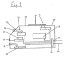
- FIG. 1 shows a sensor system 10 for determining active input variables for controlling a sunshade system 12 (see FIG. 2), which are transmitted to a controller 14 (see FIGS. 2 and 3) which, when defined switching values are reached, send drive commands to the drives 17 (see Fig. 3) of the sun protection system 12 transmitted and thus allows automatic adjustment of the sun protection system 12.
- the sensor system 10 shown in Fig. 1 is housed in a separate housing 16 which is coupled by means of connecting lines 18 to the controller 14.
- the sensor 10 must determine at least the input variables time / date, sun intensity and direction of the sunshade system to allow automatic control of the sunshade system 12 depending on the position of the sun. Especially with external sun protection systems, the detection of the additional input variables wind speed and outside temperature by the sensor 10 and a rain detector are useful.
- the sensor 10 has a radio receiver 20 which receives electromagnetic radio clock signals and forwards the calculation of the current position of the sun to the controller 14.
- the radio receiver 20 is of course formed with a suitable antenna (not shown), which ensures safe data reception location-independent within the transmission range.
- the determination of the day of the week and the summer time correction can be realized programmatically in the controller 14.
- the senor 10 may also have a clock that provides the required input variables.
- a clock that provides the required input variables.
- the determination of the input variable provides time / date on the basis the radio clock principle a nearly perfect accuracy and the possibility of automatic initial and Nacheinstellens.
- the determination of the input sun intensity takes place with the aid of a sun sensor 22, which is designed as a photoresistor, photodiode or solar cell. It is also conceivable to provide a plurality of such sensors - also of different types - for determining the solar intensity.
- the sun sensor 22 is arranged in the illustrated embodiment directly on the board of the evaluation system within the sensor housing 16 and connected via a light guide 24 with a seated on the housing outer wall lens 26. However, it is also conceivable to mount the photosensitive element itself on the outside of the housing and to establish the connection to the board by means of electrical lines.
- the sun sensor provides the controller 14 with information as to whether the sunshade system 14 or the window surface to be shaded by it is exposed to solar radiation at all, or whether, for example due to clouding, an extension of the sunshade system is necessary at all.
- the sun sensor 22 can also detect, for example, reflected sunlight from an opposite facade and cause an extension of the sunshade to a time of day, to which the controller actually assumes that the affected facade is in the shade.
- a direction sensor 28 is provided, which automatically detects the orientation of the sunshade 12 after installation, which of course assumes in the separately executed in Fig. 1 housing 16 of the sensor 10 that this in a precise defined location to the sun protection system is located.
- the direction sensor 28, in its embodiment as an electronic compass, can measure two or three axes of the final magnetic field and calculate the absolute direction from the individual components of the magnetic field. For most applications, the measurement of the two horizontal components is sufficient, since the sun protection system and thus the direction sensor 28 are aligned exactly during assembly using a spirit level. It is important to ensure that ferromagnetic components of the sun protection system, such. B.
- the electronic compass 28 may be embodied, for example, as a fluxgate sensor or as a magnetoresistive sensor.
- the senor 10 offers the possibility with the help of a wind sensor 80 to detect the input variable wind speed and thus avoid a risk of the system by mechanical overload by causing the retraction of the system in strong wind.
- a pressure sensor is used as the conventional wind sensor 30, which is arranged in the interior of the housing 16 and communicates via a hose connection 32 with the environment.
- Other conventional sensors by means of which an air flow can be detected, which can be regarded as a measure of the wind speed, are thermos probes in which the air flow cools an electrically heated probe, so that at constant heating power, the temperature or at a constant temperature, the heating power is a measure of the flow velocity is, or a strain gauge circuit, which detects the bending of a specific body exposed to the air flow as a measure of the flow velocity by means of two DMS elements and evaluates with a bridge circuit.
- the wind sensor 30 may in turn be mounted on the surface of the housing 16.
- a sensor is used as the wind sensor 80, which detects the vibrations of a reference body for detecting the wind speed, which is mounted to oscillate and exposed to the passing wind.
- Fig. 4 shows in detail the anemometer 80 with a housing 82 in which a vibration switch 84, for example a mercury or ball switch, is arranged.
- the exposed to the wind reference body 86 which may be formed for example as a ball or cylinder, is connected via a two-part mechanical connection 88, 90 with the vibration switch 84.
- a first part 86 which is integrally formed on the reference body 86, engaged in a second part 90 which is connected to a membrane 92 which is fitted in a housing opening 94.
- the membrane 94 seals the housing 82 and exerts a restoring force on the reference body 86 when it is deflected by the adjacent wind.
- the natural frequency of the resulting system is chosen so that it is well outside the frequency spectrum of the attacking wind to avoid influencing the characteristic.
- the nature of the membrane 92 affects the damping and natural frequency of the system, depending on hardness, size, material and shape. As a material, for example, a plastic is used whose elasticity properties vary only slightly over the temperature spectrum occurring in outdoor facilities.
- the natural frequency is also influenced by the moving masses and moments of inertia and the present leverage.
- the structure of the wind meter 180 corresponds to that of the wind meter 80 in Fig. 4, wherein like parts have been given the same reference numerals. Only the two holding parts are integrally formed as a holding part 188.
- a positive influence on the inflow turbulence can also be achieved by wind deflectors 96 (see FIG. 6) which at least partially surround the reference body 86 and are designed as protective gratings 98 in the wind gauge 80 shown in FIG. 6 and at the same time for protection of the reference body and also serve the sensitive membrane 92 against external influences.
- the reference body 86 may also have an ellipsoidal shape, whereby depending on the direction of flow of the characteristic Diameter and thus change the switching pulses.
- the response of the wind meter 80 can be changed with unchanged membrane 92, unchanged vibration switch 84 or magnet 184 and the same evaluation only by replacing the reference body 86, since different reference body 86 lead to a changed vortex shedding, so that the cutoff frequency of the wind meter 80 only at a higher or even at a lower wind speed is achieved.
- the diameter of the reference body is in the one to two-digit millimeter range. Good results have been obtained with a ball switch with a body diameter of 8 mm and with a mercury switch or a magnetic Hall sensor arrangement at a distance of 1 mm with a body diameter of 25 mm.
- the sensor system 10 shown in FIG. 1 further has a rain sensor 34, which can detect precipitation or moisture and especially in wet-sensitive sun protection systems, such. As awnings, can cause the retraction of the system.
- the sensor 10 also has a temperature sensor 36, the signal of which can be used as a further input variable for the controller 14.
- the microcontroller 38 is connected to the controller 14 via a two-wire or three-wire bus line 44.
- FIG. 2 shows a schematic cross-section of a lamella trap door 12, in the upper rail 46 of which a sensor 10 according to the sensor system shown in FIG. 1 without a housing and a control 14 are integrated.
- the lens 26, the temperature sensor 36 and the wind sensor 30 are provided on the outside of a shutter 48 which covers the upper part of a shaft 50 in which the Venetian blind 12 is mounted.
- the external venetian blind 12 has a Lamellenbehang 52, the individual louvers 54 are shown in Fig. 2 in the retracted position as a package gathered.
- the external venetian blind 12 has two motors 17 (see Fig. 3), by means of which the slat curtain 52 extendable and the inclination of the slats 54 is adjustable. The control of the motors is taken over by the controller 14, wherein in addition to a purely automatic control and a manual intervention for the extension length and the angle adjustment of the curtain 52 is provided.
- the functional diagram shown in Fig. 3 shows the controller 14 for the motors 17 of the Venetian blind 12 in FIG the sensors provided for determining relevant input variables.
- the already mentioned manual hand switches 56, 58 for the extension length or the angle adjustment of the curtain 52 are shown to determine further input variables.
- the handset can also be designed in the form of a remote control.
- Further input variables represent the actual extension length detected with the aid of an encoder 60 and the actual angular position of the curtain 52 detected with the aid of a further encoder 62.
- the two encoders 60, 62 can be provided on the motors 17, for example in the form of rotary encoders.
- the mentioned measured or adjusted input variables are forwarded to the multiplexer 40 and an analog-to-digital converter 42 following this, which converts the incoming sensor signals serially.
- the transducer 42 is followed by a sensor signal adaptation 64, which, for example, linearizes characteristic curves or converts signal pulses into a continuous variable.
- Sequence programs are stored on an EPROM memory module 66 which generate the output variables for controlling the motors 17 as a function of the output signal of the sensor signal adaptation 64.
- the control programs are further influenced by the contents of a memory 68 in which information about the geographic length and width of the exhibition location of the sun protection system 12 are stored, as only on the exact geographical indication an exact determination of the position of the sun relative to the sun protection system 12 is possible. However, even without this information, a good approximation for many locations is possible with the aid of a default setting.
- the controller 14 is constructed so that the values for the extension length or the angle setting manually inputted with the manual switches 56, 58 are given priority over the setting determined according to the measured input values based on the basic programming. If a manual setting is not corrected for a certain time, the controller 14 automatically adjusts the setting to the theoretical ideal course over a predefined period of several hours.
- the transitions are sigmoidal in order to allow as inconspicuous as possible a return.
- the sigmoidal transitions are realized via Bezier curves, which guarantee that the return curve always has only one turning point.
- the input variables time of day and date ascertained by the radio-controlled clock 20 serve to track the setting angle of the slats 54 to the sun's altitude, whereby the date information can compensate for season-dependent changes in the sun's path.
- special calculation formulas are stored in the controller 14, which calculate the azimuth and elevation angles of the solar radiation.
- input magnitude direction can be calculated whether the sun can shine directly on the system at all and which relative position it occupies the plant.
- These calculations can be made more precise by the information stored in the memory 68 about the geographical location of the installation 12, wherein the data can also be provided by a GPS receiver integrated into the installation. Otherwise, the geographic data is stored in memory 68 during installation of the system, for example by transmission from a mobile device GPS receiver, immediate input of geographical data or the auxiliary input of the geographical location approximately indicative information such. As postcodes or license plates.
- the other input variables sun intensity, wind speed, rain and temperature are treated so that when exceeding or falling below certain thresholds retraction of the system is caused by the controller 14. Possibly.
- these threshold values can be varied as a function of the actual extension state of the system 12 determined by the encoders 60, 62.
- a further memory module 70 designed as an EEPROM is provided, which enables an adaptive learning capability of the controller 14.
- the memory module 70 it is possible in a manual intervention to store the system state, ie all input variables and output variables used for the adaptive learning capability, namely the setting parameters of the blind, in the form of a state vector.
- the input variables used for the learning process include the time of day, month and day of the week, the wind speed, the temperature and the solar intensity, but also the signal of the humidity sensor 34.
- the controller 14 now permanently compares the input variables of all stored vectors with the actual variables of the system. If the system is again in a similar or even identical state in which previously manually determined output variables have been selected in deviation from the basic programming, then this vector is called again (recall). As a result, the stored output values corresponding to a previously made manual setting are automatically adjusted. Using the input variables, the system tries to determine the reason that led to a manual operation. Although an absolutely sure recognition of a cause is hard to achieve, with every additional input used in the adaptive learning ability, the certainty to recognize the user's will increases.
- the threshold values are not defined as fixed variables, but defined for each input variable as so-called recall range. These recall areas should be adapted only after repeated operation to provide greater safety and insensitivity to accidental manual intervention. It is therefore intended to select the recall areas very small with only a single input, so that a recall occurs only if the actual state values are identical with the stored input variables of a vector.
- the adaptation of the recall areas is carried out according to specific, defined rules that are components of the learning and control algorithms of the controller 14. If a hand setting z. B. at a certain time of day always on the same day of the week, the controller assumes that this setting should be made only on this day of the week.
- the generated Recall area is therefore limited to a weekday, but extended to all calendar weeks. If the entries are made on different days of the week, a relatively large extension of the recall area also takes place with reference to this input variable. This adaptation takes place continuously, whereby an optimal adaptation of the adaptation behavior to the desired learning behavior is possible.
- the learning algorithm is also able to weight input points of the user depending on their time distances from each other and their age. Older inputs are only used to a limited extent for the definition of the recall areas, whereby very old vectors of input quantities can also be deleted.
- the controller 14 further provides the possibility of a reset which clears all vectors and returns the algorithm to its start state in which the outputs are determined from the detected inputs only through the basic programming.
- the automatic control can also be switched off by the manual switches 56, 58.
- the sensors 10, control 14 and motors 17 of the sun protection system 12 need to supply only a conventional household power grid without additional components or even control lines, as they are found in previously implemented systems. With the connection to the power grid, the system is ready, with possibly only the data for the geographical location and / or the orientation of the system must be stored.
- the described combination of a sensor 10 with a controller 14 is also suitable for automatically controlling other sun protection systems, such. B. from awnings.
- the controller 14 can produce output signals for only one motor, for two motors (see embodiment) or even more motors.
- the basic programming must be adapted, with adapted programming the use of one and the same unit of sensor 10 and controller 14 can be used for a variety of types of sun protection.
- the nature of the sun protection system can be dispensed with individual sensors to reduce the cost of the sensor 10.
Landscapes
- Physics & Mathematics (AREA)
- General Physics & Mathematics (AREA)
- Engineering & Computer Science (AREA)
- Structural Engineering (AREA)
- Fluid Mechanics (AREA)
- Architecture (AREA)
- Civil Engineering (AREA)
- Operating, Guiding And Securing Of Roll- Type Closing Members (AREA)
- Transition And Organic Metals Composition Catalysts For Addition Polymerization (AREA)
- Power-Operated Mechanisms For Wings (AREA)
- Refuge Islands, Traffic Blockers, Or Guard Fence (AREA)
Claims (9)
- Pare-soleil avec un rideau protecteur (52), au moins un entraînement pour son positionnement et un anémomètre qui détermine, lors du dépassement d'une grandeur supérieure à une valeur seuil, une commande (14) permettant de relever le rideau (52) et qui collecte également la charge due à l'action du vent sur le pare-soleil (12) relative aux composantes de vecteur vent variant par rapport à l'horizontal, caractérisé en ce que l'anémomètre présente un capteur (84 ; 100 ; 184) destiné à collecter des vibrations lequel collecte les oscillations provoquées par le vent d'un corps de référence (86) qui est exposé au flux venteux.
- Pare-soleil selon la revendication 1, caractérisé en ce que le capteur destiné à collecter des vibrations se présente sous la forme d'un commande à rotule ou d'un contact au mercure, sous la forme d'un microphone ou sous la forme d'un capteur à effet Hall (100) interagissant avec un aimant (184).
- Pare-soleil selon la revendication 1 ou 2, caractérisé en ce que le corps de référence (86) se présente sous la forme d'un cylindre circulaire positionné de façon à pouvoir vibrer ou une bille positionné de façon à pouvoir vibrer chacun présentant un diamètre déterminé et le capteur (84) détermine au-delà d'une fréquence seuil déterminée l'enroulement du rideau (52).
- Pare-soleil selon l'une quelconque des revendications 1 à 3, caractérisé en ce que le corps de référence (86) est maintenu par une membrane pouvant vibrer (92).
- Pare-soleil selon l'une quelconque des revendications précédentes, caractérisé en ce que la fréquence propre du système pouvant vibrer composé du corps de référence (86) et de la membrane (92) se situe en dehors de la plage de référence, dans laquelle se trouve le spectre de turbulence du vent.
- Pare-soleil selon l'une quelconque des revendications précédentes, caractérisé en ce que des éléments de conduite du vent (96) sont prévus dans la direction de la circulation du vent devant le corps de référence (86), lesquels entourent, de préférence, sous la forme d'une grille de protection (98) le corps de référence (86) au moins de façon partielle.
- Pare-soleil selon l'une quelconque des revendications précédentes, caractérisé en ce qu'un capteur (60, 62) est prévu pour la collecte des valeurs réelles du rideau (52) et la commande (14) détermine la charge mécanique réelle du pare-soleil (12), à partir de la position réelle saisie pour le rideau (52) et la charge du vent mesurée.
- Pare-soleil selon l'une quelconque des revendications précédentes, caractérisé en ce que l'anémomètre est agencé avec un capteur (84 ; 100 ; 184) à proximité immédiate du pare-soleil (12) et est relié avec une commande guidant ce dernier de façon indépendante (14).
- Pare-soleil selon l'une quelconque des revendications précédentes, caractérisé en ce que l'anémomètre fait directement partie intégrante du pare-soleil prémonté en usine (12) qui est raccordable au réseau domestique traditionnel.
Applications Claiming Priority (4)
| Application Number | Priority Date | Filing Date | Title |
|---|---|---|---|
| DE19932729 | 1999-07-14 | ||
| DE19932729 | 1999-07-14 | ||
| DE19949556 | 1999-10-14 | ||
| DE19949556 | 1999-10-14 |
Publications (2)
| Publication Number | Publication Date |
|---|---|
| EP1077378A1 EP1077378A1 (fr) | 2001-02-21 |
| EP1077378B1 true EP1077378B1 (fr) | 2006-04-26 |
Family
ID=26054169
Family Applications (1)
| Application Number | Title | Priority Date | Filing Date |
|---|---|---|---|
| EP00114876A Expired - Lifetime EP1077378B1 (fr) | 1999-07-14 | 2000-07-12 | Anémomètre pour une installation de protection du soleil |
Country Status (3)
| Country | Link |
|---|---|
| EP (1) | EP1077378B1 (fr) |
| AT (1) | ATE324591T1 (fr) |
| DE (2) | DE10033831A1 (fr) |
Cited By (1)
| Publication number | Priority date | Publication date | Assignee | Title |
|---|---|---|---|---|
| US8050885B2 (en) | 2007-01-10 | 2011-11-01 | Somfy Sas | Method for determining the effects of the wind on a blind |
Families Citing this family (19)
| Publication number | Priority date | Publication date | Assignee | Title |
|---|---|---|---|---|
| AU778068B2 (en) | 2000-01-31 | 2004-11-11 | Turnils A.B. | Awning assembly and control system |
| ITMI20012507A1 (it) * | 2001-11-29 | 2003-05-29 | Jolly Motor Internat S P A | Dispositivo di protezione per porte e finestre munite di tende e/o tapparelle con avvolgimento radiocomandato |
| US6798158B2 (en) * | 2002-10-22 | 2004-09-28 | Dometic Corporation | Wind sensing awning control |
| FR2861123B1 (fr) * | 2003-10-15 | 2006-03-03 | Somfy | Procede d'initialisation et de commande d'une installation comprenant des ecrans sensibles au vent. |
| ITVE20040032A1 (it) | 2004-07-14 | 2004-10-14 | Master S R L Unipersonale | Sistema integrato per il controllo di dispositivi di protezione ambientale |
| JP2006176110A (ja) | 2004-11-29 | 2006-07-06 | Dometic Corp | アームに取り付けたセンサを有する風検出式天幕制御装置 |
| FR2912509B1 (fr) * | 2007-02-08 | 2009-05-08 | Somfy Sas | Procede de configuration d'un capteur domotique |
| FR2922585B1 (fr) * | 2007-10-19 | 2012-09-21 | Somfy Sas | Installation de protection solaire equipee d'un capteur de vent |
| DE102007059151A1 (de) * | 2007-12-08 | 2009-06-10 | Weinor Gmbh & Co. Kg | Beschattung oder Sichtschutz mit Elektromotorantrieb |
| ITTV20080004A1 (it) | 2008-01-10 | 2009-07-11 | Nice Spa | Azionamento per avvolgibili con protezione contro vento eccessivo |
| DE102008029942A1 (de) | 2008-06-17 | 2009-12-24 | Weinor Gmbh & Co. Kg | Windsensor |
| FR2941007B1 (fr) * | 2009-01-09 | 2011-01-21 | Somfy Sas | Store venitien exterieur avec moyen de determination des effets du vent |
| DE202010002146U1 (de) * | 2010-02-09 | 2011-11-23 | Jofo Pneumatik Gmbh | Windsensor |
| DE102013113365A1 (de) | 2013-12-03 | 2015-06-03 | Endress + Hauser Wetzer Gmbh + Co Kg | Verfahren zum Betreiben eines Messvorrichtung |
| CN105259928B (zh) * | 2015-11-13 | 2017-11-03 | 上海斐讯数据通信技术有限公司 | 根据风向调整设备方向的方法及装置 |
| JP7094830B2 (ja) * | 2018-08-22 | 2022-07-04 | シャープ株式会社 | ブラインド |
| EP3940185B1 (fr) * | 2020-07-17 | 2022-09-21 | Roma Kg | Dispositif de sécurité pour un store à lamelles, store à lamelles doté d'un tel dispositif de sécurité et procédé de commande permettant de commander un entraînement électromoteur de store à lamelles |
| CN114509111B (zh) * | 2022-01-26 | 2023-06-27 | 华能威海发电有限责任公司 | 一种电站锅炉异常工况检测方法及系统 |
| ES3061591T3 (en) * | 2023-04-18 | 2026-04-06 | Griesser Holding Ag | Sun protection device with detection of faults |
Family Cites Families (5)
| Publication number | Priority date | Publication date | Assignee | Title |
|---|---|---|---|---|
| DE2931956A1 (de) * | 1979-08-07 | 1981-02-26 | Mfb Neuwerk Mech Fenster | Waechtersteuerung fuer bewegliche sonnenschutzeinrichtungen an gebaeuden, insbesondere markisen |
| DE3015989A1 (de) * | 1980-04-25 | 1981-11-05 | MFB-Neuwerk Mechanische Fensterbehänge GmbH, 2850 Bremerhaven | Windsensor fuer sicherheitsschalter |
| DE9306368U1 (de) * | 1993-04-27 | 1993-07-08 | Rademacher, Wilhelm, 4292 Rhede | Verdunkelungsvorrichtung mit einer Markise, einer Außenjalousie o.dgl. |
| NL9400103A (nl) * | 1994-01-21 | 1995-09-01 | Arts Jozef E M | Wind- en zonnemelder. |
| DE20000682U1 (de) * | 2000-01-17 | 2000-03-30 | Helmut Beyers GmbH, 41066 Mönchengladbach | Vorrichtung zur Steuerung der Bewegung einer Beschattungseinrichtung |
-
2000
- 2000-07-12 DE DE10033831A patent/DE10033831A1/de not_active Withdrawn
- 2000-07-12 AT AT00114876T patent/ATE324591T1/de not_active IP Right Cessation
- 2000-07-12 EP EP00114876A patent/EP1077378B1/fr not_active Expired - Lifetime
- 2000-07-12 DE DE50012636T patent/DE50012636D1/de not_active Expired - Fee Related
Cited By (1)
| Publication number | Priority date | Publication date | Assignee | Title |
|---|---|---|---|---|
| US8050885B2 (en) | 2007-01-10 | 2011-11-01 | Somfy Sas | Method for determining the effects of the wind on a blind |
Also Published As
| Publication number | Publication date |
|---|---|
| DE10033831A1 (de) | 2001-03-08 |
| DE50012636D1 (de) | 2006-06-01 |
| ATE324591T1 (de) | 2006-05-15 |
| EP1077378A1 (fr) | 2001-02-21 |
Similar Documents
| Publication | Publication Date | Title |
|---|---|---|
| EP1077378B1 (fr) | Anémomètre pour une installation de protection du soleil | |
| EP1069277B1 (fr) | Arrangement pare-soleil avec commande de store automatique et possibilité d'intervention manuelle | |
| EP0552459B1 (fr) | Dispositif de sécurité pour volets roulants et similaires | |
| US6849842B2 (en) | Rotating shadowband pyranometer | |
| CN111727382A (zh) | 雨量计/气象站 | |
| EP1069275A2 (fr) | Dispositif de protection solaire à position adaptable selon l'incidence de la lumière | |
| EP0251311A1 (fr) | Dispositif de protection solaire | |
| DE102005048805A1 (de) | Verfahren zum Betreiben einer Windenergieanlage | |
| DE102005032550A1 (de) | Steuervorrichtung für Jalousien an Hochbauten | |
| EP0958564A1 (fr) | Dispositif de detection de vehicules | |
| DE10318695B4 (de) | Verfahren zum Betrieb einer Windenergieanlage | |
| DE4407342C2 (de) | Verdunkelungsvorrichtung mit einer Markise, einer Außenjalousie o. dgl. | |
| US3965348A (en) | Method of and apparatus for detecting light and controlling jalousies and the like | |
| DE19804036A1 (de) | Sensorsystem und Multisensorsystem zur Erfassung von klimatischen Meßdaten sowie Verfahren zur Herstellung des Sensorsystems und des Multisensorsystems | |
| EP1028861A1 (fr) | Detecteur de la hauteur du soleil | |
| EP1194690A1 (fr) | Installation d'energie eolienne a regulation de la projection de l'ombre | |
| DE102012024110A1 (de) | Vorrichtung zur Messung von Solarstrahlung | |
| DE29923046U1 (de) | Sensor für eine Verdunkelungsvorrichtung und Verdunkelungsanlage | |
| DE29924615U1 (de) | Sonnenschutzanlage mit sich dem Lichteinfall anpassender Behangeinstellung | |
| DE3016610C2 (de) | Sichtweitenmeßgerät nach dem Prinzip der Vorwärtsstreuung | |
| US3396277A (en) | Radiation sensitive irrigation device | |
| EP3038294A1 (fr) | Systeme et procede de mise a disposition de donnees sur l'environnement | |
| JP4216130B2 (ja) | 太陽追尾型センサ、及び電動ブラインドの制御装置 | |
| DE4011416A1 (de) | Witterungssensorik | |
| WO2006117226A1 (fr) | Dispositif pour detecter de la lumiere du milieu environnant et du champ avant dans une automobile |
Legal Events
| Date | Code | Title | Description |
|---|---|---|---|
| PUAI | Public reference made under article 153(3) epc to a published international application that has entered the european phase |
Free format text: ORIGINAL CODE: 0009012 |
|
| AK | Designated contracting states |
Kind code of ref document: A1 Designated state(s): AT CH DE LI |
|
| AX | Request for extension of the european patent |
Free format text: AL;LT;LV;MK;RO;SI |
|
| 17P | Request for examination filed |
Effective date: 20010817 |
|
| AKX | Designation fees paid |
Free format text: AT CH DE LI |
|
| 17Q | First examination report despatched |
Effective date: 20040826 |
|
| GRAP | Despatch of communication of intention to grant a patent |
Free format text: ORIGINAL CODE: EPIDOSNIGR1 |
|
| GRAS | Grant fee paid |
Free format text: ORIGINAL CODE: EPIDOSNIGR3 |
|
| GRAA | (expected) grant |
Free format text: ORIGINAL CODE: 0009210 |
|
| AK | Designated contracting states |
Kind code of ref document: B1 Designated state(s): AT CH DE LI |
|
| REF | Corresponds to: |
Ref document number: 50012636 Country of ref document: DE Date of ref document: 20060601 Kind code of ref document: P |
|
| PLBE | No opposition filed within time limit |
Free format text: ORIGINAL CODE: 0009261 |
|
| STAA | Information on the status of an ep patent application or granted ep patent |
Free format text: STATUS: NO OPPOSITION FILED WITHIN TIME LIMIT |
|
| 26N | No opposition filed |
Effective date: 20070129 |
|
| REG | Reference to a national code |
Ref country code: CH Ref legal event code: PCAR Free format text: ISLER & PEDRAZZINI AG;POSTFACH 1772;8027 ZUERICH (CH) |
|
| PGFP | Annual fee paid to national office [announced via postgrant information from national office to epo] |
Ref country code: AT Payment date: 20090723 Year of fee payment: 10 Ref country code: CH Payment date: 20090727 Year of fee payment: 10 |
|
| PGFP | Annual fee paid to national office [announced via postgrant information from national office to epo] |
Ref country code: DE Payment date: 20090923 Year of fee payment: 10 |
|
| REG | Reference to a national code |
Ref country code: CH Ref legal event code: PL |
|
| PG25 | Lapsed in a contracting state [announced via postgrant information from national office to epo] |
Ref country code: DE Free format text: LAPSE BECAUSE OF NON-PAYMENT OF DUE FEES Effective date: 20110201 Ref country code: CH Free format text: LAPSE BECAUSE OF NON-PAYMENT OF DUE FEES Effective date: 20100731 Ref country code: LI Free format text: LAPSE BECAUSE OF NON-PAYMENT OF DUE FEES Effective date: 20100731 |
|
| REG | Reference to a national code |
Ref country code: DE Ref legal event code: R119 Ref document number: 50012636 Country of ref document: DE Effective date: 20110201 |
|
| PG25 | Lapsed in a contracting state [announced via postgrant information from national office to epo] |
Ref country code: AT Free format text: LAPSE BECAUSE OF NON-PAYMENT OF DUE FEES Effective date: 20100712 |