EP1077404A2 - Système et procédé pour la création programmatique d'un programme graphique - Google Patents
Système et procédé pour la création programmatique d'un programme graphique Download PDFInfo
- Publication number
- EP1077404A2 EP1077404A2 EP00117301A EP00117301A EP1077404A2 EP 1077404 A2 EP1077404 A2 EP 1077404A2 EP 00117301 A EP00117301 A EP 00117301A EP 00117301 A EP00117301 A EP 00117301A EP 1077404 A2 EP1077404 A2 EP 1077404A2
- Authority
- EP
- European Patent Office
- Prior art keywords
- program
- graphical program
- new
- graphical
- programmatically
- Prior art date
- Legal status (The legal status is an assumption and is not a legal conclusion. Google has not performed a legal analysis and makes no representation as to the accuracy of the status listed.)
- Ceased
Links
Images












Classifications
-
- G—PHYSICS
- G06—COMPUTING OR CALCULATING; COUNTING
- G06F—ELECTRIC DIGITAL DATA PROCESSING
- G06F8/00—Arrangements for software engineering
- G06F8/30—Creation or generation of source code
- G06F8/34—Graphical or visual programming
-
- H—ELECTRICITY
- H04—ELECTRIC COMMUNICATION TECHNIQUE
- H04L—TRANSMISSION OF DIGITAL INFORMATION, e.g. TELEGRAPHIC COMMUNICATION
- H04L67/00—Network arrangements or protocols for supporting network services or applications
- H04L67/01—Protocols
- H04L67/12—Protocols specially adapted for proprietary or special-purpose networking environments, e.g. medical networks, sensor networks, networks in vehicles or remote metering networks
-
- H—ELECTRICITY
- H04—ELECTRIC COMMUNICATION TECHNIQUE
- H04L—TRANSMISSION OF DIGITAL INFORMATION, e.g. TELEGRAPHIC COMMUNICATION
- H04L9/00—Cryptographic mechanisms or cryptographic arrangements for secret or secure communications; Network security protocols
- H04L9/40—Network security protocols
-
- H—ELECTRICITY
- H04—ELECTRIC COMMUNICATION TECHNIQUE
- H04L—TRANSMISSION OF DIGITAL INFORMATION, e.g. TELEGRAPHIC COMMUNICATION
- H04L69/00—Network arrangements, protocols or services independent of the application payload and not provided for in the other groups of this subclass
- H04L69/30—Definitions, standards or architectural aspects of layered protocol stacks
- H04L69/32—Architecture of open systems interconnection [OSI] 7-layer type protocol stacks, e.g. the interfaces between the data link level and the physical level
- H04L69/322—Intralayer communication protocols among peer entities or protocol data unit [PDU] definitions
- H04L69/329—Intralayer communication protocols among peer entities or protocol data unit [PDU] definitions in the application layer [OSI layer 7]
-
- Y—GENERAL TAGGING OF NEW TECHNOLOGICAL DEVELOPMENTS; GENERAL TAGGING OF CROSS-SECTIONAL TECHNOLOGIES SPANNING OVER SEVERAL SECTIONS OF THE IPC; TECHNICAL SUBJECTS COVERED BY FORMER USPC CROSS-REFERENCE ART COLLECTIONS [XRACs] AND DIGESTS
- Y10—TECHNICAL SUBJECTS COVERED BY FORMER USPC
- Y10S—TECHNICAL SUBJECTS COVERED BY FORMER USPC CROSS-REFERENCE ART COLLECTIONS [XRACs] AND DIGESTS
- Y10S715/00—Data processing: presentation processing of document, operator interface processing, and screen saver display processing
- Y10S715/961—Operator interface with visual structure or function dictated by intended use
- Y10S715/965—Operator interface with visual structure or function dictated by intended use for process control and configuration
- Y10S715/966—Computer process, e.g. operation of computer
- Y10S715/967—Visual or iconic programming
Definitions
- the present invention relates to the field of graphical programming, and in particular to a system and method for programmatically creating a graphical program.
- high level text-based programming languages have been used by programmers in writing applications programs.
- Many different high level text-based programming languages exist including BASIC, C, FORTRAN, Pascal, COBOL, ADA, APL, etc.
- Programs written in these high level languages are translated to the machine language level by translators known as compilers or interpreters.
- the high level text-based programming languages in this level, as well as the assembly language level, are referred to as text-based programming environments.
- Examples of fields in which computer systems are employed to model and/or control physical systems are the fields of instrumentation, process control, industrial automation, and simulation.
- Computer modeling or control of devices such as instruments or industrial automation hardware has become increasingly desirable in view of the increasing complexity and variety of instruments and devices available for use.
- computer programs used to control such systems had to be written in conventional text-based programming languages such as, for example, assembly language, C, FORTRAN, BASIC, or Pascal.
- U.S. Patent Nos. 4,901,221; 4,914,568; 5,291,587; 5,301,301; and 5,301,336; among others, to Kodosky et al disclose a graphical system and method for modeling a process, i.e., a graphical programming environment which enables a user to easily and intuitively model a process.
- the graphical programming environment disclosed in Kodosky et al can be considered the highest and most intuitive way in which to interact with a computer.
- a graphically based programming environment can be represented at a level above text-based high level programming languages such as C, Pascal, etc.
- the method disclosed in Kodosky et al allows a user to construct a diagram using a block diagram editor, such that the diagram created graphically displays a procedure or method for accomplishing a certain result, such as manipulating one or more input variables to produce one or more output variables.
- data structures may be automatically constructed which characterize an execution procedure which corresponds to the displayed procedure.
- the graphical program may be compiled or interpreted by a computer using these data structures. Therefore, a user can create a computer program solely by using a graphically based programming environment. This graphically based programming environment may be used for creating virtual instrumentation systems, industrial automation systems, modeling processes, and simulation, as well as for any type of general programming.
- Kodosky et al teaches a graphical programming environment wherein a user places or manipulates icons in a block diagram using a block diagram editor to create a data flow "program.”
- a graphical program for controlling or modeling devices such as instruments, processes or industrial automation hardware, is referred to as a virtual instrument (VI).
- VI virtual instrument
- a user may create a front panel or user interface panel.
- the front panel includes various front panel objects, such as controls or indicators, that represent or display the respective input and output that will be used by the graphical program or VI, and may include other icons which represent devices being controlled.
- corresponding icons or terminals may be automatically created in the block diagram by the block diagram editor.
- the user can place terminal icons or input/output blocks in the block diagram which may later cause the display of corresponding front panel objects in the front panel, either at edit time or at run time.
- the user selects various functions that accomplish his desired result and connects the function icons together.
- the functions may be connected in a data flow and/or control flow format.
- the functions may be connected between the terminals of the respective controls and indicators.
- the user creates or assembles a data flow program, referred to as a block diagram, representing the graphical data flow which accomplishes his desired function.
- the assembled graphical program may then be compiled or interpreted to produce machine language that accomplishes the desired method or process as shown in the block diagram.
- a user may input data to a virtual instrument using front panel controls. This input data propagates through the data flow block diagram or graphical program and appears as changes on the output indicators.
- the front panel can be analogized to the front panel of an instrument.
- the front panel can be analogized to the MMI (Man Machine Interface) of a device.
- the user may adjust the controls on the front panel to affect the input and view the output on the respective indicators.
- the front panel may be used merely to view the input and output, and the input may not be interactively manipulable by the user during program execution.
- graphical programming has become a powerful tool available to programmers.
- Graphical programming environments such as the National Instruments LabVIEW product have become very popular.
- Tools such as LabVIEW have greatly increased the productivity of programmers, and increasing numbers of programmers are using graphical programming environments to develop their software applications.
- graphical programming tools are being used for test and measurement, data acquisition, process control, man machine interface (MMI), supervisory control and data acquisition (SCADA) applications, simulation, and machine vision applications, among others.
- MMI man machine interface
- SCADA supervisory control and data acquisition
- a user typically creates a graphical program within a graphical programming environment by interactively or manually placing icons or nodes representing the desired blocks of functionality on a diagram, and connecting the icons/nodes together to represent the data flow of the program.
- the ability to programmatically create/edit graphical programs enables a graphical program to automatically be created/edited without this type of interactive user intervention.
- a system and method for programmatically creating/editing graphical programs is described herein.
- One embodiment of the present invention comprises a computer-implemented system and method for programmatically/dynamically creating or editing a graphical program.
- a first program or client program is created, wherein the first program specifies creation of a new graphical program.
- the first program when executed, the first program is operable to programmatically create the new graphical program.
- the graphical program may be programmatically created with little or no user input specifying the new graphical program during this creating.
- the new graphical program that is created may be a graphical program of any of various types, e.g., a graphical program created specifically so that a particular graphical programming development environment is operable to edit and/or execute the graphical program.
- the new graphical program may include a plurality of graphical program objects.
- the new graphical program may have a diagram portion including a plurality of interconnected nodes which visually indicate functionality of the new graphical program.
- the new graphical program may also have a user interface portion including various user interface objects, such as one or more user interface panels having controls for specifying user input to the graphical program and/or indicators for displaying output from the graphical program.
- the first program may be a program of any of various types.
- the first program may be a text-based program, such as a program written using C, C++, Java, Basic, or another text-based programming language.
- the first program may itself be a graphical program.
- the first program may call an application programming interface (API) usable for programmatically creating the new graphical program.
- API application programming interface
- a text-based program may include text-based code for calling various API functions or methods, while a graphical program may include various graphical nodes supported by the API.
- the new graphical program is programmatically created, in response to executing the first program.
- the first program is operable to cause creation of the new graphical program.
- the first program may specify the inclusion of various objects in the new graphical program.
- the first program may also specify other aspects of the graphical program, such as: interconnections between diagram objects, connections between diagram objects and user interface objects, positions of objects, sizes of objects, and properties or configuration of objects (e.g., configuration of data types, parameters, etc.), among other aspects of the graphical program.
- the first program may include all executable logic necessary for programmatically creating the new graphical program.
- the first program is operable to interface with a server program, e.g., a graphical programming development environment application, in order to request the server program to create the new graphical program.
- a server program e.g., a graphical programming development environment application
- the first program may call a graphical program creation API supported by the server program.
- the server program is executable to create the specified graphical program.
- the server program may execute on the same computer system as the first program or may execute on a different computer system, e.g., a different computer system connected by a network.
- a similar method may be used to modify an existing graphical program.
- the first program instead of specifying creation of a new graphical program, specifies the modification of an existing graphical program.
- the first program is then operable to programmatically modify the existing graphical program.
- the first program may include a reference to the existing graphical program and may include various API calls to modify the graphical program, e.g., by adding one or more objects to the graphical program, changing connections between graphical program objects, changing various properties of graphical program objects, etc.
- the ability to programmatically create/edit graphical programs enables applications and tools to automatically create or modify a graphical program or a portion of a graphical program.
- any operation which a user may perform while interactively assembling or editing a graphical program e.g., connect two objects, change the position of an object, change the color of an object, etc. may be performed programmatically.
- an interactive wizard tool may present a series of user interface dialogs to a user, collect information from the user, and use the collected information to dynamically generate or edit a corresponding graphical program.
- Such wizard tools may be included in a third-party application.
- the National Instruments IMAQ Vision Builder application dynamically generates graphical programs for analyzing images, based on user-provided information.
- a program translator may dynamically create a graphical program from a text-based program, such as a C language program.
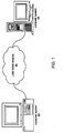
- Figure 1 Computer System Connected to a Network
- Figure 1 illustrates an exemplary computer network in which a computer system 82 is connected through a network 84 to a second computer system 86.
- the computer system 82 and the second computer system 86 can be any of various types, as desired.
- the network 84 can also be any of various types, including a LAN (local area network), WAN (wide area network), or the Internet, among others.
- the computer system 82 includes or stores a client computer program that programmatically creates or edits a graphical program or a portion of a graphical program.
- the client program may use an API to call a server program, such as a graphical programming environment application, which performs the actual operations of creating or editing the graphical program.
- the server program may reside on the computer system 82 or on the second computer system 86.
- the client program may interface with the server program indirectly through a proxy component, such as an ActiveX component
- the proxy component may reside on the computer system 82 or on the second computer system 86 or on a third computer system-connected to the network 84.
- the client, server, and proxy software programs/components may be implemented in any of various ways, including procedure-based techniques, component-based techniques, and/or object-oriented techniques, among others.
- the programs may be written using any combination of text-based or graphical programming languages. Also, the programs may be written using distributed modules or components so that each of the client, server, and proxy may reside on any combination of computer system 82, computer system 86, and other computer systems connected to the network 84.
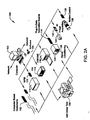
- Figures 2A and 2B illustrate exemplary systems which may store or use client/server/proxy programs for programmatically creating/editing graphical programs for instrumentation, process control, or other purposes. These programs may of course be stored in or used by other types of systems as desired.
- FIG. 2A illustrates an instrumentation control system 100.
- the system 100 comprises a host computer 102 which connects to one or more instruments.
- the host computer 102 comprises a CPU, a display screen, memory, and one or more input devices such as a mouse or keyboard as shown.
- the computer 102 connects through the one or more instruments to analyze, measure, or control a unit under test (UUT) or process 150.
- the host computer 102 may store client, server, and/or proxy computer programs or components for programmatically creating or editing a graphical program, such as a graphical program which interacts with or controls the one or more instruments.
- the computer 102 may be either of computers 82 or 86.
- the one or more instruments may include a GPIB instrument 112 and associated GPIB interface card 122, a data acquisition board 114 and associated signal conditioning circuitry 124, a VXI instrument 116, a PXI instrument 118, a video device 132 and associated image acquisition card 134, a motion control device 136 and associated motion control interface card 138, and/or one or more computer based instrument cards 142, among other types of devices.
- the GPIB instrument 112 is coupled to the computer 102 via the GPIB interface card 122 provided by the computer 102.
- the video device 132 is coupled to the computer 102 via the image acquisition card 134
- the motion control device 136 is coupled to the computer 102 through the motion control interface card 138.
- the data acquisition board 114 is coupled to the computer 102, and may interface through signal conditioning circuitry 124 to the UUT.
- the signal conditioning circuitry 124 preferably comprises an SCXI (Signal Conditioning eXtensions for Instrumentation) chassis comprising one or more SCXI modules 126.
- the GPIB card 122, the image acquisition card 134, the motion control interface card 138, and the DAQ card 114 are typically plugged in to an I/O slot in the computer 102, such as a PCI bus slot, a PC Card slot, or an ISA, EISA or MicroChannel bus slot provided by the computer 102.
- I/O slot such as a PCI bus slot, a PC Card slot, or an ISA, EISA or MicroChannel bus slot provided by the computer 102.
- these cards 122, 134, 138 and 114 are shown external to computer 102 for illustrative purposes.
- the VXI chassis or instrument 116 is coupled to the computer 102 via a VXI bus, MXI bus, or other serial or parallel bus provided by the computer 102.
- the computer 102 preferably includes VXI interface logic, such as a VXI, MXI or GPIB interface card (not shown), which interfaces to the VXI chassis 116.
- VXI interface logic such as a VXI, MXI or GPIB interface card (not shown), which interfaces to the VXI chassis 116.
- the PXI chassis or instrument is preferably coupled to the computer 102 through the computer's PCI bus.
- a serial instrument may also be coupled to the computer 102 through a serial port, such as an RS-232 port, USB (Universal Serial bus) or IEEE 1394 or 1394.2 bus, provided by the computer 102.
- a serial port such as an RS-232 port, USB (Universal Serial bus) or IEEE 1394 or 1394.2 bus, provided by the computer 102.
- USB Universal Serial bus
- IEEE 1394 or 1394.2 bus provided by the computer 102.
- the instruments are coupled to the unit under test (UUT) or process 150, or are coupled to receive field signals, typically generated by transducers.
- the system 100 may be used in a data acquisition and control application, in a test and measurement application, a process control application, or a man-machine interface application.
- FIG. 2B illustrates an exemplary industrial automation system 160.
- the industrial automation system 160 is similar to the instrumentation or test and measurement system 100 shown in Figure 2A. Elements which are similar or identical to elements in Figure 2A have the same reference numerals for convenience.
- the system 160 comprises a computer 102 which connects to one or more devices or instruments.
- the computer 102 comprises a CPU, a display screen, memory, and one or more input devices such as a mouse or keyboard as shown.
- the computer 102 connects through the one or more devices to a process or device 150 to perform an automation function, such as MMI (Man Machine Interface), SCADA (Supervisory Control and Data Acquisition), portable or distributed data acquisition, process control, advanced analysis, or other control.
- MMI Man Machine Interface
- SCADA Supervisory Control and Data Acquisition
- the computer 102 may store client, server, and/or proxy computer programs or components for programmatically creating or editing a graphical program, such as a graphical program that is involved with the automation function performed by the automation system 160.
- the computer 102 may be either of computers 82 or 86.
- the one or more devices may include a data acquisition board 114 and associated signal conditioning circuitry 124, a PXI instrument 118, a video device 132 and associated image acquisition card 134, a motion control device 136 and associated motion control interface card 138, a fieldbus device 170 and associated fieldbus interface card 172, a PLC (Programmable Logic Controller) 176, a serial instrument 182 and associated serial interface card 184, or a distributed data acquisition system, such as the Fieldpoint system available from National Instruments, among other types of devices.
- a data acquisition board 114 and associated signal conditioning circuitry 124 may include a data acquisition board 114 and associated signal conditioning circuitry 124, a PXI instrument 118, a video device 132 and associated image acquisition card 134, a motion control device 136 and associated motion control interface card 138, a fieldbus device 170 and associated fieldbus interface card 172, a PLC (Programmable Logic Controller) 176, a serial instrument 182 and associated serial interface card 184, or
- the DAQ card 114, the PXI chassis 118, the video device 132, and the image acquisition card 136 are preferably connected to the computer 102 as described above.
- the serial instrument 182 is coupled to the computer 102 through a serial interface card 184, or through a serial port, such as an RS-232 port, provided by the computer 102.
- the PLC 176 couples to the computer 102 through a serial port, Ethernet port, or a proprietary interface.
- the fieldbus interface card 172 is preferably comprised in the computer 102 and interfaces through a fieldbus network to one or more fieldbus devices.
- Each of the DAQ card 114, the serial card 184, the fieldbus card 172, the image acquisition card 134, and the motion control card 138 are typically plugged in to an I/O slot in the computer 102 as described above. However, these cards 114, 184, 172, 134, and 138 are shown external to computer 102 for illustrative purposes. In typical industrial automation systems a device will not be present of each interface type, and in fact many systems may only have one or more devices of a single interface type, such as only PLCs. The devices are coupled to the device or process 150.
- the computer system 102 preferably includes a memory medium on which one or more computer programs or software components according to the present invention are stored.
- the term "memory medium" is intended to include an installation medium, e.g., a CD-ROM, floppy disks 104, or tape device, a computer system memory such as DRAM, SRAM, EDO RAM, Rambus RAM, etc., or a non-volatile memory such as a magnetic media, e.g., a hard drive, or optical storage.
- the memory medium may comprise other types of memory as well, or combinations thereof.
- the memory medium may be located in a first computer in which the programs are, executed, or may be located in a second different computer which connects to the first computer over a network, such as the Internet In the latter instance, the second computer provides the program instructions to the first computer for execution.
- the computer system 102 may take various forms, including a personal computer system, mainframe computer system, workstation, network appliance, Internet appliance, personal digital assistant (PDA), television system or other device.
- PDA personal digital assistant
- the term "computer system” can be broadly defined to encompass any device having at least one processor which executes instructions from a memory medium.
- the client program, server program, and/or the resulting graphical program that is created or edited are designed for data acquisition/generation, analysis, and/or display, and for controlling or modeling instrumentation or industrial automation hardware.
- the server program is the National Instruments LabVIEW graphical programming environment application, which provides specialized support for developers of instrumentation applications.
- the client program may also be a program involved with instrumentation or data acquisition.
- Figures 2A and 2B are exemplary only, and graphical programs for any of various types of purposes may be generated or edited by client/server/proxy programs for any of various types of purposes, where the client/server/proxy prrograms are stored in and execute on any of various types of systems.
- a spreadsheet program may act as a client program and may use the API described herein to dynamically generate a graphical program which analyzes spreadsheet data and displays the results of the analysis to a user.
- Figure 3 is a block diagram of the computer system illustrated in Figures 1, 2A and 2B. It is noted that any type of computer system configuration or architecture can be used as desired, and Figure 3 illustrates a representative PC embodiment. It is also noted that the computer system may be a general purpose computer system as shown in Figures 2A and 2B, a computer implemented on a VXI card installed in a VXI chassis, a computer implemented on a PXI card installed in a PXI chassis, or other types of embodiments. The elements of a computer not necessary to understand the present invention have been omitted for simplicity.
- the computer 102 includes at least one central processing unit or CPU 160 which is coupled to a processor or host bus 162.
- the CPU 160 may be any of various types, including an x86 processor, e.g., a Pentium class, a PowerPC processor, a CPU from the SPARC family of RISC processors, as well as others.
- Main memory 166 is coupled to the host bus 162 by means of memory controller 164.
- the main memory 166 stores computer programs according to the present invention.
- the main memory 166 also stores operating system software as well as the software for operation of the computer system, as well known to those skilled in the art.
- the computer programs of the present invention will be discussed in more detail below.
- the host bus 162 is coupled to an expansion or input/output bus 170 by means of a bus controller 168 or bus bridge logic.
- the expansion bus 170 is preferably the PCI (Peripheral Component Interconnect) expansion bus, although other bus types can be used.
- the expansion bus 170 includes slots for various devices such as the data acquisition board 114 (of Figure 2A), a GPIB interface card 122 which provides a GPIB bus interface to the GPIB instrument 112 (of Figure 2A), and a VXI or MXI bus card 186 coupled to the VXI chassis 116 for receiving VXI instruments.
- the computer 102 further comprises a video display subsystem 180 and hard drive 182 coupled to the expansion bus 170.
- Figures 4 - 5 Interactive Creation of a Graphical Program by a User
- Figure 4 is a flowchart diagram illustrating one embodiment of how a user may interactively or manually create or edit a graphical program. As shown in the flowchart and described below, the user manually adds various objects to a graphical program, connects them together, etc. In contrast, the present invention comprises a system and method for programmatically creating or editing a graphical program without requiring this type of user interaction.
- the steps axe performed by a user creating or editing a graphical program in a graphical programming environment.
- the user may create or edit a user interface panel for displaying a graphical user interface.
- the user interface panel may comprise controls for accepting user input, displaying information such as program output, or both.
- the user interface panel may include buttons, selectable lists, text boxes, graph controls, images, etc.
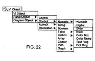
- a user may "drop" various controls or other objects onto the user interface panel, e.g., by selecting the desired control from a control palette.
- Figure 5A illustrates a simple user interface panel.
- Step 420 is not necessarily performed.
- a user interface panel may not be desired, a user interface panel may be inherently specified during creation of the block diagram, or a user interface panel may automatically be created as the user creates the executable portions of the graphical program.
- a graphical program may include a block diagram comprising objects referred to herein as "nodes" which are connected together to model the program execution logic and data flow or control flow.
- a block diagram node may be displayed as an icon representing the type or functionality of the node.
- Figure 5B illustrates a simple block diagram. As a user adds objects to the user interface panel, the graphical programming environment may automatically create a corresponding object on the block diagram. Such block diagram nodes which correspond to user interface panel objects are referred to herein as user interface nodes.
- the Figure 5B block diagram node labeled "The result of 2.0 + 3.0 was:" is a user interface node corresponding to the Figure 5A user interface output indicator.
- User interface nodes may be connected with other objects or nodes in the block diagram to participate in the program logic and data/control flow. User interface nodes may map input/output between a user interface panel and a block diagram. For example, the user interface node in Figure 5B receives data and displays the data in the corresponding user interface indicator in Figure 5A.
- step 422 of Figure 4 the user adds other objects/nodes to or edits other objects/nodes of the graphical program.
- objects or nodes may include function nodes which perform predefined functional operations such as numeric functions, Boolean functions, string functions, array functions, error functions, file functions, application control functions, etc.
- function nodes which perform predefined functional operations such as numeric functions, Boolean functions, string functions, array functions, error functions, file functions, application control functions, etc.
- the block diagram shown in Figure 5B uses an addition function node to add two constants together.
- the user may also add other types of nodes to the graphical program.
- nodes may be added which represent numeric constants.
- Figure 5B illustrates numeric constant nodes representing the floating point constants 2.0 and 3.0.
- nodes which may be added include subprogram nodes for calling a graphical subprogram, global or local variable nodes for defining and using variables, etc.
- the user may also add other types of objects to the graphical program. For example, objects representing programmatic structures such as for loops, while loops, case structures, etc. may be added.
- the user may add nodes and other types of objects to a graphical program in various ways, e.g., by selecting a node or object from a palette that displays icons representing the various nodes and objects.
- a graphical program may use the API by incorporating specialized nodes to create or open a graphical program, add objects to or edit objects of a graphical program, etc. These specialized nodes are described below.
- the user connects or "wires" the graphical program objects in order to achieve the desired executable logic and data flow or control flow.
- the objects may include input and output terminals, and the user may connect the output terminal of one node to the input terminal of another node, etc.
- Figure 5B illustrates one embodiment of how objects may be connected.
- output terminals of the two numeric constant nodes are connected to the input terminals of an addition function node.
- the addition function node performs the addition operation on the numeric input.
- the output terminal of the addition function node is connected to the input of the user interface indicator node so that the result of the addition operation is displayed in the user interface panel shown in Figure 5A.
- Programmatic structure objects may also include terminals which integrate them with the other objects of the graphical program.
- a while loop may comprise a condition terminal to which an output terminal of a node supplying a boolean value may be connected to signify when the loop should end.
- the user saves or runs the graphical program.
- the graphical program may be saved in any of various formats. For example, a tree of data structures may be built which represents the various elements of the graphical program and the relationships among the elements, and the data structures may be saved in a binary or text format. If the graphical program includes user interface panels, these panels may also be saved.
- the user may also execute the graphical program.
- the user may run the graphical program in any of various ways. For example, a graphical programming environment may allow a program to be run from within the development environment, or the user may create a standalone program and run the program, etc.
- steps 420 through 426 typically occur in an iterative manner and typically occur in various orders. For example a user may add a user interface control to a user interface panel, then connect a user interface node corresponding to the control to another node, then add and connect a function node to the program, then run the program to test it, then change the way a node is connected, etc.
- the flowchart of Figure 4 is exemplary, and various steps may be combined, omitted, added, or modified as required or desired for developing different graphical programs or using different embodiments of graphical program development environments.
- Figure 4 illustrates one embodiment of how a user may create/edit a graphical program, and the process may differ for other embodiments.
- a client program which may be a graphical program
- the server program may be a graphical programming environment operable to respond to the client program's requests for creating/editing the graphical program.
- the graphical programming environment is the LabVIEW graphical programming environment available from National Instruments.
- LabVIEW graphical programming environment available from National Instruments.
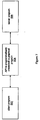
- Figure 6 is a flowchart diagram illustrating one embodiment of a method for programmatically creating a graphical program.
- a first program is created, wherein the first program specifies creation of a new graphical program.
- the first program when executed, the first program is operable to programmatically create the new graphical program.
- the graphical program may be programmatically created with little or no user input specifying the new graphical program during this creating.
- the graphical program is programmatically created with no user input required.
- the user may be prompted for certain decisions during programmatic creation, such as the type of graphical program, the look and feel of the user interface in the graphical program, the number or degree of comments contained within the graphical program, etc.
- the new graphical program that is created may be a graphical program of any of various types, e.g., a graphical program created specifically so that a particular graphical programming development environment is operable to edit and/or execute the graphical program.
- the new graphical program may include a plurality of graphical program objects.
- the new graphical program may have a diagram portion including a plurality of interconnected nodes which visually indicate functionality of the new graphical program.
- the new graphical program may also have a user interface portion including various user interface objects, such as one or more user interface panels having controls for specifying user input to the graphical program and/or indicators for displaying output from the graphical program.
- the first program that is created in step 450 may be a program of any of various types.
- the first program may be a text-based program, such as a program written using C, C++, Java, Basic, or another text-based programming language.
- the first program may itself be a graphical program.
- the first program may be a program interactively created by a user, e.g., as described above with reference to Figures 5A and 5B.
- the first program may call an application programming interface (API) usable for programmatically creating the new graphical program.
- API application programming interface
- a text-based program may include text-based code for calling various API functions or methods
- a graphical program may include various graphical nodes supported by the API.
- step 452 the first program is executed.
- the new graphical program is programmatically created, in response to executing the first program.
- the first program is operable to cause creation of the new graphical program.
- the first program may specify the inclusion of various objects in the new graphical program.
- the first program may also specify other aspects of the graphical program, such as: interconnections between diagram objects, connections between diagram objects and user interface objects, positions of objects, sizes of objects, and properties or configuration of objects (e.g., configuration of data types, parameters, etc.), among other aspects of the graphical program.
- the first program may include all executable logic necessary for programmatically creating the new graphical program.
- the first program is operable to interface with a server program, e.g., a graphical programming development environment application, in order to request the server program to create the new graphical program.
- a server program e.g., a graphical programming development environment application
- the first program may call a graphical program creation API supported by the server program.
- the server program is executable to create the specified graphical program.
- the server program may execute on the same computer system as the first program or may execute on a different computer system, e.g., a different computer system connected by a network.
- the method of Figure 6 is illustrated and is described above in terms of creating a new graphical program. It is noted that a similar method may be used to modify an existing graphical program.
- the first program instead of specifying creation of a new graphical program, specifies the modification of an existing graphical program.
- the first program is then operable to programmatically modify the existing graphical program.
- the first program may include a reference to the existing graphical program and may include various API calls to modify the graphical program. e.g., by adding one or more objects to the graphical program, changing connections between graphical program objects, changing various properties of graphical program objects, etc.
- Figure 7 is a block diagram illustrating the abstract relationship between a client program 502 (e.g., the first program illustrated in Figure 6), an API 504 to programmatically create/edit a graphical program, and a server program 506.
- the client program 502 may be any of various types of programs.
- the client program 502 may be a graphical program.
- the client program 502 may also be a text-based program such as a C++ program, a Visual Basic program, a Java program, etc., or any combination of these or other languages.
- the client program 502 may execute independently or may execute within an execution subsystem of an application development environment.
- the client program 502 may call the API 504 in any of various ways.
- a client graphical program may include graphical nodes corresponding to the API 504.
- One embodiment of a set of graphical nodes which a client graphical program may utilize to create/edit a graphical program is described in detail below.
- a client graphical program may also interface with text-based code which calls the API 504.
- the client graphical program may be a LabVIEW graphical program which includes code interface nodes.
- the client program 502 may call the API 504 in various other ways.
- the server program 506 may expose a component such as an ActiveX component, CORBA component, JavaBeans component, etc., and the client program 502 may obtain a reference to the object to invoke functions or methods of the API 504.
- the API 504 may also be integrated with the language or development environment of the client program 502, e.g., as a library.
- the client program 502 communicates with a server program 506.
- the server program 506 is operable to perform the actions indicated by the API.
- the server program may be operable to create a new graphical program, add objects to the graphical program, connect graphical program objects, etc.
- the server program 506 is preferably an instance of a graphical programming environment.
- the server program 506 is an instance of the LabVIEW graphical programming environment.
- Figure 7 illustrates the abstract relationship between the client program 502, the API 504, and the server program 506.
- various layers may exist which implement the elements of the Figure 7 relationship.
- the client program 502 may be a part of a larger software application
- the server program 506 may receive information sent by the client program via an intermediate server, etc.
- Figure 8 illustrates one embodiment of the client/server relationship of Figure 7.
- the client program 502 is a graphical program
- the server program 506 is an instance of a graphical programming environment application.
- the client graphical program 502 may execute independently or may execute within an execution subsystem 510, such as an execution subsystem of a graphical programming environment.
- the client graphical program 502 may be a graphical program created using the same graphical programming environment as the graphical programming environment server 506.
- the client graphical program 502 may be a LabVIEW graphical program
- the server program 506 may be a LabVIEW application.
- the client graphical program 502 utilizes the API 504 of Figure 7 to communicate with the graphical programming environment server 506.
- the client graphical program 502 may include a graphical node which requests the graphical programming environment 506 to open an existing graphical program, one or more modify nodes which request the graphical programming environment to modify the graphical program, e.g., by modifying properties of graphical program objects, etc.
- the functionality of the API 504 may be implemented in various ways.
- the client graphical program 512 interfaces with a runtime library 514 which includes code corresponding to the API nodes.
- the graphical program may interface with other types of software components which implement the API, such as ActiveX, CORBA, or JavaBeans components.
- the client graphical program 502 may execute in a different location than the graphical programming environment server 506.
- the client and server programs may communicate using any of various types of protocols, such as the TCP/IP network protocol.
- the runtime library 514 may include TCP/IP client code 516
- the graphical programming environment server 506 may include TCP/IP server code 518.
- the TCP/IP server code 518 may listen for requests from TCP/IP client code 516. Once a connection is established, the client code 516 and server code 518 may exchange messages using a message protocol.
- the block diagram of Figure 8 illustrates an architecture in which the client program 502 communicates with a server program 506 via a defined protocol.
- the client program and the server program must know the required communications protocol.
- the client graphical program 502 is a LabVIEW graphical program
- the server program 506 is a LabVIEW application instance.
- the LabVIEW client program may include certain nodes, such as the nodes described below, for communicating with the LabVIEW application server and causing the LabVIEW application server to create/edit a graphical program.
- Figure 9 illustrates an embodiment of the client/server relationship of Figure 7, in which a client program 502 may communicate with a server program 506 without needing to use a protocol specific to the client or server programs.
- the client program 502 is a program which communicates with the server program 506 via an object request broker (ORB), and the server program 506 is a service operable to create/edit a graphical program, referred to as a graphical program service.
- the client program 502 may be a text-based program, such as a Visual Basic, C++, Java, etc. program, or may be a graphical program.
- the graphical program service 506 may be implemented in any of various ways.
- the service 506 may encapsulate or call a portion of a graphical programming environment which is operable to create/edit a graphical program, or alternatively, the service 506 may be a standalone program operable to create/edit a graphical program.
- Figure 9 illustrates the general relationship in which a client program references a service object via an ORB.
- the ORB may be any of various ORBs, such as the ActiveX/DCOM system, a CORBA system, a Java application environment, etc.
- the client program 502 requests a reference to the graphical program service 506 from the ORB 534.
- the ORB may create a proxy stub 532 for the client program 502 and a server stub 536 for the graphical program service.
- the proxy stub 532 may communicate through the ORB infrastructure 534 with the server stub 536, and the server stub 536 may interface with the graphical program service 506.
- the proxy stub 532 may comprise API functions/methods to create/edit a graphical program which the client program 502 may invoke, and the ORB may transparently cause the graphical program service 506 to execute the corresponding functions/methods.
- the ORB 532 may be the ActiveX/DCOM system
- the client program 502 may be an automation client program, such as a Visual Basic automation client
- the graphical program service 506 may be an ActiveX component provided by a graphical programming environment.
- the client program 502 may create a reference to the ActiveX graphical program service component in the standard way and may invoke methods on the component to create/edit a graphical program.
- the ActiveX component may then execute appropriate portions of the graphical programming environment code in order to perform the requested operations.
- the ORB may be a Java application environment
- the client program 502 and the graphical program service 506 may be Java programs.
- the client program 502 may request an interface to the graphical program 506 and may use the interface to request the graphical program service 506 to create/edit a graphical program.
- FIG. 9 illustrates a general architecture in which the client program 502 communicates with a graphical program service 506 via intermediate software proxies or components.
- the graphical program service is a software component such as an ActiveX component which is provided by the LabVIEW graphical programming environment for client programs to use to programmatically create/edit graphical programs.
- the server program 506 of Figure 7 is operable to receive requests to create/edit a graphical program from a client and perform the actual operations of creating/editing the graphical program.
- the server program of Figure 7 is an application instance of the LabVIEW graphical programming environment.
- the LabVIEW environment provides specialized support for developers of instrumentation and industrial automation applications, and a LabVIEW graphical program may be referred to as a virtual instrument or VI.
- the LabVIEW environment comprises functionality referred to as "VI Server" which enables client programs to communicate with the LabVIEW environment
- the VI Server functionality enables client programs to create or edit a LabVIEW graphical program or VI.
- a client program which requests LabVIEW to create/edit a VI may itself be a VI.
- a client VI may include particular nodes in the VI which utilize the VI Server functionality of a LabVIEW instance to request the LabVIEW instance to create a new VI, add objects to the VI, etc. These nodes are described in Figures 10-23 below, and Figures 24-27 illustrate exemplary uses of these nodes.
- LabVIEW also provides components such as ActiveX components which enable text-based programs such as Visual Basic programs, Visual C++ programs, etc. to access the VI Server functionality. In the preferred embodiment, these components enable text-based programs to perform all of the functions described below.
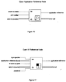
- Figure 10 illustrates the Open Application Reference node.
- the Open Application Reference node returns a reference to a VI Server application running on the specified computer. If an empty string is specified for machine name , then the node returns a reference to the local LabVIEW application in which this function is running. If a machine name is specified, then the node attempts to establish a TCP connection with a remote VI Server on that machine on the specified port.
- the application reference output can be used as an input to the Property and Invoke nodes described below to get or set properties and invoke methods on the application.
- the application reference output is used as the input to the Open VI Reference function to obtain references to VIs in that application.
- the reference is closed with the Close Application or VI Reference function. If the user forgets to close this reference, the reference closes automatically when the top level VI associated with this function finishes executing. However, closing the reference operates to conserve the resources involved in maintaining the connection.
- Figure 11 illustrates the Open VI Reference node.
- the Open VI Reference node returns a reference to a VI specified by a name string or path to the VI's location on disk. This reference may then be used to edit the VI.
- references can only be obtained to standard VIs. This excludes Control, Typedef, and Global VIs.
- the Open VI Reference node can be used to obtain a reference to any VI.
- references to VIs in another LabVIEW application are obtained by wiring an application reference (obtained from the Open Application Reference function) to this function.
- the path input refers to the file system on the remote LabVIEW computer. If a reference to the local LabVIEW application is wired the same behavior is obtained as if nothing had been wired to the application reference input.
- the password is provided to the password string input. If the incorrect password is provided, the Open VI Reference function returns an error and an invalid VI reference. If no password is provided when opening a reference to a VI that is password protected, the reference can still be obtained, operations can only be performed that do not edit the VI.
- the Open VI Reference function verifies at run tune that the referenced VI's connector pane matches that of the type specifier input.
- the reference closes automatically when the top-level VI associated with this function finishes executing. However, closing the reference operates to conserve the resources involved in maintaining the connection.
- a dedicated data space is allocated for that reference.
- This data space is preferably always used and is used only in conjunction with the output VI reference. This can lead to some new behaviors in LabVIEW. For example, parallel calls (using the Call By Reference node) to a reentrant VI using the same VI reference do not execute in parallel, but executes serially, one after the other. As another example, a reentrant VI could get a reference to itself (allocating a new data space) and call itself recursively through the Call By Reference node. It is noted that allocating a data space dynamically is both time consuming and memory consuming and is not generally recommended for implementing recursive algorithms.
- a VI reference is similar to what is known as a function pointer in other languages. However, in LabVIEW, these function pointers also can be used to reference VIs across a network.
- the path is interpreted on the remote machine in the context of the remote file system.
- the path is expressed using the local computer's path separators, but is translated to the remote computer's path separators when the request arrives there.
- My HD: ⁇ LabVIEW VIs ⁇ foo.vi would be used.
- C:labview:foo.vi would be used.
- Figure 12 illustrates the New VI Reference node.
- the New VI Reference node creates a new VI and outputs a reference to the new VI.
- Figure 13 illustrates the Open VI Object Reference node.
- the Open VI Object Reference node outputs a reference to an object contained in a VI.
- the following describes the inputs and outputs of the Open VI Object Reference node:
- Figure 14 illustrates the New VI Object Reference node.
- the New VI Object Reference node creates a new VI object and outputs a reference to the new VI object.
- the following describes the inputs and outputs of the New VI Object Reference node:
- FIG. 15 illustrates the Upcast Reference node.
- the Upcast Reference node casts the type of a reference to an object to the type of a superclass for the object. The following describes the inputs and outputs of the Upcast Reference node:
- FIG. 16 illustrates the Downcast Reference node.
- the Downcast Reference node casts the type of a reference to an object to the type of a subclass. The following describes the inputs and outputs of the Downcast Reference node:
- Figure 17 illustrates the Close Application or VI Reference node.
- the Close Application or VI Reference node closes an open VI or the connection to a LabVIEW application instance. The following describes the inputs and outputs of the Close Application or VI Reference node:
- FIG 18 illustrates the Call By Reference node.
- the Call By Reference node may be used to call a VI, such as a VI which has been created programmatically.
- the Call By Reference node is similar to a sub-VI node in that either can be used to call a VI.
- a sub-VI node is statically linked to a particular VI that the user determines when he/she drops the node on the diagram.
- the VI that is called is determined dynamically at run time by the value of the VI reference wired to the reference input at the top of the node.
- the VI which is called by the Call By Reference node may be on a different computer.
- the top of the Call By Reference node includes four terminals: an input/output pair of flow through VI reference terminals, and an input/output pair of flow through error clusters.
- the VI reference input accepts wires only from strictly-typed VI references. Below these terminals is an area within which a connector pane resides (is displayed) that is identical to that of a VI with its terminals showing (rather than its icon).
- the connector pane of the strictly-typed VI reference input determines the pattern and data types of this connector pane which is displayed in the Call By Reference node icon. The user wires to these terminals just as he/she would to a normal sub-VI.
- the connector pane will adapt automatically to that of the input VI reference's connector pane. However, if any of them are wired, the node does not adapt automatically, and the user must explicitly change the connector pane (possibly breaking those wires) by popping up on the node and selecting the Adapt To Reference Input menu item.
- Figure 19 illustrates the Property node.
- the Property node sets (writes) or gets (reads) application, VI and VI object property information.
- the Property node may be used to create/edit a graphical program.
- the property node may be used to change the color of a user interface object, etc.
- the user pop ups on one of the name terminals and selects Properties .
- the list of available properties to select from may depend on the type of object wired to the reference input.
- To set property information the user pop ups and selects Change to Write .
- To get property information the user pop ups and selects Change to Read . Some properties are read only, so Change to Write cannot be seen in the popup menu.
- the user desires to add items to the node, the user pop ups and selects Add Element or clicks and drags the node to expand the number of items in the node. The properties are changed in the order from top to bottom. If an error occurs on one of the properties, the node stops at that property and returns an error. In this case, no further properties are handled.
- the error string reports which property caused the error. If the small direction arrow on a property is on the left, then the property value is being set. If the small direction arrow on the property is on the right, the user is getting the property value.
- Each property name has a short or long name which can be changed by popping up and selecting Name Format . Another name format is no name where only the type is displayed for each property.
- the Property node may be used to access or affect a number of different properties, including VI (virtual instrument) and application properties.
- Figure 20 illustrates the Invoke node.
- the Invoke node invokes a method or action on a VI or VI object.
- the Invoke node may be used to create/edit a graphical program. For example, a method may be invoked on a block diagram node to reposition the node, wire the node to another node, etc. Most methods have parameters associated with them. To select the method, the user pops up anywhere on the node and select Methods . Once the user selects the method, the associated parameters appear in the node, as shown in Figure 20. The number of parameters shown may vary, depending on which method is selected. Each parameter may have an input terminal, output terminal, or both. An output terminal may be present for the return value of the method.
- the Invoke node may be used to invoke a number of different methods, including VI (virtual instrument), VI object, and application methods.
- the inputs and outputs of the Invoke node are as follows:
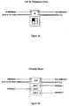
- Figure 21 illustrates user interface controls which may be placed on a front panel in order to interactively obtain a reference, such as a reference to a VI or an object of a VI.
- Figure 21 illustrates exemplary front panel refnum controls for Application, Generic VI, and Strictly-typed VI data types. It is noted however, that a graphical programming system may provide such front panel refnum controls for any of the various objects associated with a VI, including terminals, etc.
- the image in each refnum icon indicates the type of the refnum.
- VI references may be sub-divided into two classes of VIs: the Generic VI and the Strictly typed VI.
- a Generic VI reference is used to perform editing operations (e.g., setting properties or invoking functions) on any VI
- a Strictly-typed VI reference is used to call a dynamically loaded VI as a sub-VI, and to perform operations that do not edit or change the VI.
- the Application class refnum icon displays the LabVIEW application icon.
- the Generic VI class refnum icon displays the VI file icon.
- the Strictly-typed VI class refnum icon depicts the connector pane that defines the class.
- a front panel refnum provides a reference to an appropriate entity.
- the Application refnum provides a reference to a graphical programming application, e.g. a LabVIEW application
- the generic VI refnum provides a reference to a generic virtual instrument or generic graphical program
- the strictly typed VI refnum provides a reference to a specified graphical program or VI.
- Other types of refnums provide references to their corresponding graphical program objects.
- the user selects a VI Server front panel refnum control and places this refnum control in a front panel of a VI.
- the user then configures the refnum to be an appropriate type, such as an Application refnum, a Generic VI refnum, a Strictly-typed VI refnum, or another type of refnum.
- the refnum control takes on the respective appearance by the class selected by the user. For example, if the user drops the front panel refnum control on the front panel and configures the refnum to be of the Application class, the refnum takes on the Application icon appearance shown in Figure 21.
- Figure 24 illustrates an exemplary client graphical program that uses the nodes described above to dynamically create the graphical program of Figures 5A and 5B.
- Various sections of the Figure 24 program are labeled in the diagram with the purpose of the code.
- a New VI Reference node is used to create a new graphical program. Since no application reference is passed to the New VI Reference node, the new graphical program is created by the default local LabVIEW application instance.
- the New VI Reference node outputs a reference to the new graphical program, and the Property node "reference" input receives this reference.
- the Property node sets properties of the graphical program, specifying that the user interface panel window and block diagram window of the graphical program are open. As described above, a user may pop up a menu to select the desired property of an object to get or set. The list of displayed properties may vary according to what type of object the reference input references.
- the Open VI Object Reference Node is used to obtain a reference to the "x" input terminal of the Addition function node.
- the reference to the "x" input terminal is passed to an Invoke node, which creates a constant value of 2.0 that is wired to the "x" input terminal.
- an Invoke node which creates a constant value of 2.0 that is wired to the "x" input terminal.
- a user may pop up a menu to select the desired method to invoke on an object. The list of displayed methods may vary according to what type of object the reference input references.
- an Open VI Object Reference Node and an Invoke node are used to create a constant value of 3.0 that is wired to the "y" input terminal of the Addition function node.
- an Open VI Object Reference Node and an Invoke node are used to create a user interface indicator control that is wired to the output terminal of the Addition function node.
- Figures 25 and 26 illustrate a slightly more complex example of a graphical program than the program of Figures 5A and 5B.
- Figure 27 illustrates a client graphical program that uses the nodes described above to create the program shown in Figures 25 and 26.
- the client graphical program of Figure 27 may be created interactively by a user, as described above.
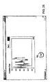
- Figure 25 illustrates a user interface panel which includes a waveform chart control and a button control.
- Figure 26 illustrates a block diagram representing the execution and data flow of the program.
- Each of the user interface controls of Figure 25 has a corresponding user interface node in the Figure 26 block diagram.
- the rectangular object 610 with the arrowhead is a while loop.
- the icon 612 is the condition terminal for the while loop 610.
- the icon 616 represents a random number generator function node.
- the output terminal of the random number node 616 is connected to the input terminal of the waveform chart user interface node 618.
- Figure 25 shows how the waveform chart may appear after several loop iterations.
- the icon 620 is simply a "wait" function icon with an input constant of 100, which causes a pause of 100 milliseconds for each loop iteration.
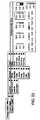
- Figure 27 illustrates a client graphical program which uses the nodes described above to dynamically create the graphical program of Figures 25 and 26.
- the client graphical program is broken into sections, and the function of each section is described.
- a New VI Reference node is used to create a new graphical program. Since no application reference is passed to the New VI Reference node, the new graphical program is created by the default local LabVIEW application instance.
- the New VI Reference node outputs a reference to the new graphical program, and the Property node "reference" input receives this reference.
- the Property node sets various properties of the graphical program. For example, the origin and coordinate bounds of the user interface panel (front panel) are set, the coordinate bounds of the block diagram window are set, etc. As described above, a user may pop up a menu to select the desired property of an object to get or set. The list of displayed properties may vary according to what type of object the reference input references.
- a New VI Object Reference node is used to create the waveform chart user interface control.
- the reference to the new graphical program generated by the New VI Reference node in section 1 is connected as the "owner reference" input of the New VI Object Reference node.
- Other inputs are also connected which specify the type of object to create, the position to place the object, etc.
- the New VI Object Reference node outputs a reference to the waveform control.
- the property node of section 2 receives this reference input and changes the Y axis range of the waveform control to range from 0.0 to 1.0.
- a New VI Object Reference node is used to create the stop button user interface control.
- a positioning function is used to specify the position input for the node, in order to appropriately position the button under the waveform chart on the user interface panel.
- a New VI Object Reference node is used to create and position the while loop.
- an Open VI Object Reference node is used to obtain a reference to the user interface node on the block diagram corresponding to the waveform chart user interface control.
- a "Control Terminal" data type is specified as the class of the object for which to obtain a reference
- 'Waveform Chart is specified as the name of the object for which to obtain a reference
- the reference to the new graphical program is specified as the owner reference.
- the Invoke node invokes a "Move" method on the waveform chart user interface node, moving it into the area bounded by the while loop.
- a user may pop up a menu to select the desired method to invoke on an object.
- the list of displayed methods may vary according to what type of object the reference input references.
- a New VI Object Reference node is used to create the random number generator function. As shown, the reference to the while loop created in section 4 is used as the "owner reference" input of the New VI Object Reference node. Thus, the random number function is created within the while loop.
- an Invoke node is used to connect the random number generator function to the waveform chart user interface node.
- the reference to the waveform chart user interface node is connected to the reference input of the Invoke node.
- the Invoke node displays a list of relevant input parameters.
- the reference to the random number generator function node is supplied as the "wire source” input parameter.
- a New VI Object Reference node is used to create a wait function node
- an Open VI Object Reference node is used to obtain a reference to the "milliseconds to wait" input terminal of the wait function node
- an Invoke node is used to create a numeric constant of 100 which is connected to the "milliseconds to wait" input terminal of the wait function node.
- section 9 of Figure 27 the stop button user interface node is moved inside the area bounded by the while loop. Section 9 is similar to section 5 described above.
- Section 10 of Figure 27 a New VI Object Reference node is used to create a "Not" boolean function inside the while loop. Section 10 is similar to the sections described above.
- an Invoke node is used to connect the stop button user interface node to the Not function node. Section 11 is similar to section 7 described above.
- a Property node is used to obtain a reference to the loop condition terminal of the while loop.
- the reference to the condition terminal is connected as the reference input to the Invoke node shown in section 12, and the Invoke node connects the output of the Not function node to the condition terminal of the while loop, sirnilarly to the sections described above.
- an Invoke node is used to run the newly created graphical program.
- the reference to the new graphical program is connected to the reference input of the Invoke node, and a "Run" method is selected as the method to invoke on the program.
- a "Run" method is selected as the method to invoke on the program.
- the exemplary graphical programs of Figures 24 - 27 utilize the specific graphical programming API described above, i.e., the nodes shown in Figures 10 - 20.
- This particular graphical API is exemplary only, and many alternative embodiments are contemplated.
- a graphical program may include other types of modify nodes to modify aspects of a newly created or existing graphical program.
- client programs may also be text-based programs.
- a text-based program may obtain a reference to a software component which includes an interface with functions or methods to perform the operations of the nodes described above.
- a program may obtain a reference to an ActiveX component, where the interface for the ActiveX component includes a CreateNewProgram method which is comparable to the New VI Reference node, a GetProgramObjectReference method which is comparable to the Open VI Object Reference node described above, etc.
- various types of software components are provided which enable programs of various languages executing on various systems to programmatically create/edit graphical programs.
- modern component-based software architecture and object oriented design techniques make it relatively straightforward to encapsulate portions of code and provide various interfaces to the code.
- a service to create/edit a graphical program may be exposed as an ActiveX component, a CORBA component, a Java component, etc.
- the implementation of the nodes described above and the implementation of components for use in text-based programs is based on a common code base.
- the server program of Figure 7 is a LabVIEW application instance which comprises VI Server functionality.
- the user can configure which parts of the VI Server are available to other applications, as well as enable or disable particular protocols and specify which server resources are exported.
- This section describes VI Server configuration.
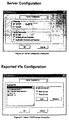
- the options shown in Figure 28 specify through which communication protocols other applications can access the VI Server: TCP/IP or ActiveX protocols. If the user enables TCP/IP , the user must enter the Port number that client applications use to connect to the server. When the user allows other applications to connect using TCP/IP, the user should also configure which Internet hosts have access to the server. See the TCP/IP Access Configuration section for more information.
- TCP/IP Access Configuration section See the TCP/IP Access Configuration section for more information.
- For more information about the VI server ActiveX interface refer to U.S. provisional patent application Serial No. 60/056,528 titled "System and Method for Accessing Object Capabilities in a Graphical Program" filed 8/21/97, whose inventors are Ram Kudukoli, Robert Dye, and Murali Parthasarathy, which is hereby incorporated by reference.
- Server Configuration selected, the user also specifies which server resources are available to applications that access the VI Server. The following server resources are available:
- Application Methods and Properties allows applications to read and set the properties of the server.
- TCP/IP server access is enabled for port 5151 and the ActiveX server access is disabled.
- the server allows remote clients to call VIs, but does not allow access to VI or application methods and properties.
- the default server settings have ActiveX enabled and TCP/IP disabled. By default, VI Calls is enabled, but VI Methods and Properties and Application Methods and Properties are disabled.
- the user may specify which VIs remote applications can access.
- the user selects Edit>>Preferences on the server computer, then selects Server: Exported VIs from the drop down menu.
- the dialog box appears as shown in Figure 29.
- the user may also specify various options which allow or disallow client programs to perform particular operations regarding creating/editing graphical programs. For example, the user may set up the server to allow clients to create new programs, but disallow the editing of existing programs, or the user may set a password required to edit existing programs, etc.
- the Server Exported VIs options allows the user to specify which VIs other applications can access through the VI Server.
- the Exported VIs list specifies which VIs are exported. To change an entry, the user selects it from the list, then types into the text box at the tight of the Exported VIs list. To specify whether remote computers can or cannot access that VI, the user clicks on the Allow Access or Deny Access radio buttons. The user clicks the Add button to insert a new entry after the current selection. The user clicks the Remove button to delete the current selection. The user clicks and drags an entry to change its position within the Exported VIs list. If an entry allows access to VIs, a check mark appears next to the entry. If an entry denies access to VIs, a "cross out" symbol appears next to the entry. If no symbol appears next to the entry, the syntax of the entry is incorrect.
- Each entry in the list describes a VI name or a VI path and may contain wildcard characters (see the paragraph below on wildcard characters). Entries that contain path separators are compared against VI paths, while entries that do not contain path separators are compared against VI names only.
- the server examines the Exported VIs list to determine whether to grant access to the requested VI. If an entry in the list matches the requested VI, the server either allows or denies access to that VI, based on how that entry is set up. If a subsequent entry also matches the VI, its access permission is used in place of the previous permission. If there is not a VI in the list that matches the requested VI, access to the VI is denied.
- the user can use wildcard characters in the Exported VIs list so an entry in the list matches more than one VI.
- wildcard characters can be used:
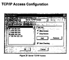
- the user When the user allows remote applications to access the VI Server using the TCP/IP protocol, the user should specify which Internet hosts have access to the server. To configure the clients that have access, the user selects Edit>>Preferences on the server machine and selects Server: TCP/IP Access from the drop down menu. The options appear in the Preferences dialog box as shown in Figure 30.
- TCP/IP Access allows the user to specify which clients can access the VI Server.
- the TCP/IP Access List describes clients that either have access to or are denied access to the LabVIEW server.
- the user selects it from the list, then types into the text box at the right of the TCP/IP Access List.
- the server When a client tries to open a connection to the server, the server examines the entries in the TCP/IP Access List to determine whether it grants access to the client. If an entry in the list matches the client's address, the server either allows or denies access, based on how the user set up the entry. If a subsequent entry also matches the client's address, its access permission is used in place of the previous permission. (For example, in Figure 29 above, a.test.site.com in the TCP/IP Access List is allowed access even though the list indicates that all addresses ending in .test.site.com are not allowed access. See the paragraph on wildcards later in this document.) If no entry matches the client's address, access is denied.
- IP Internet
- An Internet (IP) address such as "130.164.123.123”
- the conversion from a domain name to its corresponding IP address is called name resolution .
- the conversion from an IP address to its domain name is called name lookup.
- Name lookups and name resolutions are done through system calls that access domain name system (DNS) servers on the Internet.
- DNS domain name system
- a name lookup or resolution can fail when the system does not have access to a DNS server, or when the address or name is not valid.
- a resolution problem occurs when an entry contains a domain name that cannot be resolved into an IP address.
- a lookup problem occurs when an entry contains a partial domain name, such as ".natinst.com", and the lookup for the client's IP address fails.
- the Strict Checking option determines how the server treats access list entries that cannot be compared to a client's IP address because of resolution or lookup problems.
- Strict Checking is enabled, a denying access list entry in the TCP/IP Access List that encounters a resolution problem is treated as if it matched the client's IP address.
- Strict Checking is disabled, an access list entry that encounters a resolution problem is ignored.
- the user enters its domain name or IP address.
- the * wildcard can be used when specifying Internet host addresses. For example, the user can specify all hosts within the domain domain.com with the entry * .domain.com. The user can specify all hosts in the subnet whose first two octets are 130.164 with the entry 130.164.*. The entry * matches all addresses.
- the default TCP/IP Access settings allow access only to clients on the server machine.
- the respective access node e.g., the New VI Reference node, the Invoke node, the Property node, etc.
- the respective access node operates to manipulate or access the VI in a similar manner as if the VI were in the client graphical program.
Landscapes
- Engineering & Computer Science (AREA)
- Software Systems (AREA)
- Theoretical Computer Science (AREA)
- General Engineering & Computer Science (AREA)
- Computer Networks & Wireless Communication (AREA)
- Signal Processing (AREA)
- Physics & Mathematics (AREA)
- General Physics & Mathematics (AREA)
- Computer Security & Cryptography (AREA)
- Health & Medical Sciences (AREA)
- Computing Systems (AREA)
- General Health & Medical Sciences (AREA)
- Medical Informatics (AREA)
- Stored Programmes (AREA)
Applications Claiming Priority (4)
| Application Number | Priority Date | Filing Date | Title |
|---|---|---|---|
| US14994299P | 1999-08-19 | 1999-08-19 | |
| US149942P | 1999-08-19 | ||
| US09/518,492 US7159183B1 (en) | 1999-08-19 | 2000-03-03 | System and method for programmatically creating a graphical program |
| US518492 | 2000-03-03 |
Publications (2)
| Publication Number | Publication Date |
|---|---|
| EP1077404A2 true EP1077404A2 (fr) | 2001-02-21 |
| EP1077404A3 EP1077404A3 (fr) | 2006-05-24 |
Family
ID=26847171
Family Applications (1)
| Application Number | Title | Priority Date | Filing Date |
|---|---|---|---|
| EP00117301A Ceased EP1077404A3 (fr) | 1999-08-19 | 2000-08-18 | Système et procédé pour la création programmatique d'un programme graphique |
Country Status (2)
| Country | Link |
|---|---|
| US (1) | US7159183B1 (fr) |
| EP (1) | EP1077404A3 (fr) |
Cited By (42)
| Publication number | Priority date | Publication date | Assignee | Title |
|---|---|---|---|---|
| EP1296232A3 (fr) * | 2001-09-24 | 2003-08-06 | Siemens Energy & Automation, Inc. | Système et méthode pour la programmation d'un automate programmable et pour la génération de données de configuration à partir d'un serveur central |
| WO2004006205A3 (fr) * | 2002-07-03 | 2005-03-03 | Nat Instr Corp | Deploiement sans fil/execution distribuee de programmes graphiques vers des capteurs intelligents |
| US7062716B2 (en) | 1999-08-19 | 2006-06-13 | National Instruments Corporation | System and method for enhancing the readability of a graphical program |
| US7069517B2 (en) | 1999-08-19 | 2006-06-27 | National Instruments Corporation | System and method for programmatically creating graphical program code in a graphical program |
| US7120876B2 (en) | 1999-08-19 | 2006-10-10 | National Instruments Corporation | System and method for programmatically generating a graphical program in response to user input |
| US7139979B2 (en) | 2002-06-10 | 2006-11-21 | National Instruments Corporation | Displaying operations in an application using a graphical programming representation |
| US7168072B2 (en) | 2002-07-18 | 2007-01-23 | National Instruments Corporation | Wizard for programmatically analyzing and modifying time-critical graphical programs |
| US7185287B2 (en) | 2002-07-03 | 2007-02-27 | National Instruments Corporation | Wireless deployment / distributed execution of graphical programs to smart sensors |
| US7200838B2 (en) | 2000-12-20 | 2007-04-03 | National Instruments Corporation | System and method for automatically generating a graphical program in response to a state diagram |
| US7210117B2 (en) | 1999-08-19 | 2007-04-24 | National Instruments Corporation | System and method for programmatically generating a graphical program in response to program information |
| US7370275B2 (en) | 2003-10-24 | 2008-05-06 | Microsoft Corporation | System and method for providing context to an input method by tagging existing applications |
| US7480906B2 (en) | 2002-08-14 | 2009-01-20 | National Instruments Corporation | Programmatically analyzing and modifying a remote graphical program via a network |
| RU2371758C2 (ru) * | 2003-10-24 | 2009-10-27 | Майкрософт Корпорейшн | Интерфейс программирования для компьютерной платформы |
| US7650574B2 (en) | 2004-05-11 | 2010-01-19 | National Instruments Corporation | Visually indicating problems found during programmatic analysis of a graphical program |
| US7689917B2 (en) | 2000-12-20 | 2010-03-30 | National Instruments Corporation | Automatically generating a sub-graphical program in response to user input configuring a graphical program node |
| US7694229B2 (en) | 2000-04-06 | 2010-04-06 | Microsoft Corporation | System and theme file format for creating visual styles |
| US7721254B2 (en) | 2003-10-24 | 2010-05-18 | Microsoft Corporation | Programming interface for a computer platform |
| US7743362B2 (en) | 1998-02-17 | 2010-06-22 | National Instruments Corporation | Automatic generation of application domain specific graphical programs |
| US7761846B2 (en) | 2005-08-16 | 2010-07-20 | National Instruments Corporation | Graphical programming methods for generation, control and routing of digital pulses |
| US7765278B2 (en) | 2001-08-14 | 2010-07-27 | National Instruments Corporation | Wireless deployment and execution of a graphical program to a measurement device |
| US7836426B2 (en) | 2004-05-06 | 2010-11-16 | National Instruments Corporation | Automatic generation of application domain specific graphical programs |
| US7917863B2 (en) | 2000-06-13 | 2011-03-29 | National Instruments Corporation | System and method for graphically creating a sequence of motion control operations |
| US7954059B2 (en) | 2006-07-24 | 2011-05-31 | National Instruments Corporation | Automatic conversion of text-based code having function overloading and dynamic types into a graphical program for compiled execution |
| US7975233B2 (en) | 2006-07-24 | 2011-07-05 | National Instruments Corporation | Automatic conversion of a textual language into a graphical program representation |
| US7992129B2 (en) | 2000-06-05 | 2011-08-02 | National Instruments Corporation | System and method for programmatically generating a graphical program based on a sequence of motion control, machine vision, and data acquisition (DAQ) operations |
| US7996782B2 (en) | 2007-06-08 | 2011-08-09 | National Instruments Corporation | Data transfer indicator icon in a diagram |
| US8010465B2 (en) | 2008-02-26 | 2011-08-30 | Microsoft Corporation | Predicting candidates using input scopes |
| US8028242B2 (en) | 2006-08-04 | 2011-09-27 | National Instruments Corporation | Diagram with configurable wires |
| US8028241B2 (en) | 2006-08-04 | 2011-09-27 | National Instruments Corporation | Graphical diagram wires whose appearance represents configured semantics |
| US8074201B2 (en) | 2002-07-10 | 2011-12-06 | National Instruments Corporation | Deployment and execution of a program on an embedded device |
| US8108784B2 (en) | 2006-08-04 | 2012-01-31 | National Instruments Corporation | Configuring icons to represent data transfer functionality |
| US8271943B2 (en) | 2007-04-24 | 2012-09-18 | National Instruments Corporation | Automatically generating a graphical program with a plurality of models of computation |
| US8397214B2 (en) | 2004-05-14 | 2013-03-12 | National Instruments Corporation | Generating a hardware description for a programmable hardware element based on a graphical program including multiple physical domains |
| US8423981B2 (en) | 2009-06-18 | 2013-04-16 | National Instruments Corporation | Compiling a graphical program having a textual language program portion for a real time target |
| US8453111B2 (en) | 2004-05-14 | 2013-05-28 | National Instruments Corporation | Generating a hardware description for a programmable hardware element based on a graphical program including multiple models of computation |
| US8458653B2 (en) | 2009-09-29 | 2013-06-04 | National Instruments Corporation | Debugging a graphical program deployed on a programmable hardware element |
| US8458608B2 (en) | 2000-04-06 | 2013-06-04 | Microsoft Corporation | Focus state themeing |
| US8479109B2 (en) | 1999-08-19 | 2013-07-02 | National Instruments Corporation | Programmatically generating a graphical program in response to user input |
| US8612637B2 (en) | 2011-09-25 | 2013-12-17 | National Instruments Corportion | Configuring buffers with timing information |
| US8612871B2 (en) | 2006-08-04 | 2013-12-17 | National Instruments Corporation | Graphical diagram which automatically determines a data transport mechanism for wires based on configured policies |
| CN105511875A (zh) * | 2015-12-04 | 2016-04-20 | 福建星网锐捷网络有限公司 | 硬件资源的访问方法及装置 |
| EP3171266A1 (fr) * | 2015-11-16 | 2017-05-24 | Rockwell Automation Technologies, Inc. | Modélisation et mise en place de gadget logiciel d'interface utilisateur |
Families Citing this family (36)
| Publication number | Priority date | Publication date | Assignee | Title |
|---|---|---|---|---|
| US6879998B1 (en) * | 2000-06-01 | 2005-04-12 | Aerocast.Com, Inc. | Viewer object proxy |
| US7454483B2 (en) * | 2003-05-14 | 2008-11-18 | Microsoft Corporation | Method and apparatus for configuring servers |
| US20040268300A1 (en) * | 2003-06-13 | 2004-12-30 | Camille Huin | Graphical computer programming |
| US7827526B2 (en) * | 2003-06-13 | 2010-11-02 | Analog Devices, Inc. | Stacking and repeating graphical controls |
| US7620704B2 (en) * | 2003-06-30 | 2009-11-17 | Microsoft Corporation | Method and apparatus for configuring a server |
| EP1652070A2 (fr) | 2003-07-10 | 2006-05-03 | Computer Associates Think, Inc. | Systeme et procede de generation d'un module d'extension d'interface utilisateur graphique exploitable sur le web |
| US20050010877A1 (en) * | 2003-07-11 | 2005-01-13 | Arthur Udler | System and method for dynamic generation of a graphical user interface |
| WO2005008469A2 (fr) * | 2003-07-11 | 2005-01-27 | Computer Associates Think, Inc. | Systeme et procede permettant de creer un element d'interface graphique (gui) |
| US8046578B1 (en) * | 2004-04-14 | 2011-10-25 | Hewlett-Packard Development Comopany, L.P. | System and method for providing HTML authentication using an access controller |
| US7849412B2 (en) * | 2004-05-21 | 2010-12-07 | Computer Associates Think, Inc. | System and method for generating a web control in a Windows development environment |
| US7523440B2 (en) * | 2004-11-16 | 2009-04-21 | The Mathworks, Inc. | Dynamic generation of formatted user interfaces in software environments |
| US10216372B1 (en) | 2004-12-06 | 2019-02-26 | The Mathworks, Inc. | Automatic import to a graphical model |
| US7814457B2 (en) * | 2005-01-19 | 2010-10-12 | Sap Ag | System and method for revising flow diagrams displaying a process |
| US7853931B2 (en) * | 2005-01-19 | 2010-12-14 | Sap Ag | System and method for automatically generating flow diagrams |
| US7610576B2 (en) * | 2005-01-19 | 2009-10-27 | Sap Ag | System and method for simultaneous display of processes and associated files |
| US20060206827A1 (en) * | 2005-03-10 | 2006-09-14 | Siemens Medical Solutions Usa, Inc. | Live graphical user interface builder |
| US8365086B2 (en) * | 2005-05-03 | 2013-01-29 | The Mathworks, Inc. | System and method for building graphical instrument panels |
| CN100468327C (zh) * | 2005-11-10 | 2009-03-11 | 鸿富锦精密工业(深圳)有限公司 | 量测程序生成系统及方法 |
| US7949422B1 (en) * | 2007-06-22 | 2011-05-24 | Vermont Machine Tool Corporation | Machine tool control system |
| US8744829B1 (en) | 2007-07-19 | 2014-06-03 | The Mathworks, Inc. | Computer aided design environment with electrical and electronic features |
| US8630829B1 (en) | 2007-07-19 | 2014-01-14 | The Mathworks, Inc. | Computer aided design environment with electrical and electronic features |
| US8756340B2 (en) * | 2007-12-20 | 2014-06-17 | Yahoo! Inc. | DNS wildcard beaconing to determine client location and resolver load for global traffic load balancing |
| US8677310B2 (en) * | 2008-06-30 | 2014-03-18 | Rockwell Automation Technologies, Inc. | Industry template abstracting and creation for use in industrial automation and information solutions |
| US8255869B2 (en) * | 2008-06-30 | 2012-08-28 | Rockwell Automation Technologies, Inc. | Industry template customization and transclusion for use in industrial automation and information solutions |
| US8832579B2 (en) * | 2008-08-12 | 2014-09-09 | Rockwell Automation Technologies, Inc. | System for creation and management of industrial automation and information solutions and services |
| US7966523B2 (en) * | 2008-08-21 | 2011-06-21 | Rockwell Automation Technologies, Inc. | Industrial automation and information solutions having industry specific modalities |
| CN103069383B (zh) * | 2010-06-02 | 2016-09-28 | 艾伦智能科技公司 | 具有图形用户界面的装置及开发多媒体计算机应用程序的方法 |
| EP2453326B1 (fr) * | 2010-11-10 | 2019-12-25 | Siemens Aktiengesellschaft | Procédé et système destinés à la commande d'une machine issue de la technique d'automatisation |
| US20140278328A1 (en) * | 2013-03-15 | 2014-09-18 | Nvidia Corporation | System, method, and computer program product for constructing a data flow and identifying a construct |
| US9323502B2 (en) | 2013-03-15 | 2016-04-26 | Nvidia Corporation | System, method, and computer program product for altering a line of code |
| US9015643B2 (en) | 2013-03-15 | 2015-04-21 | Nvidia Corporation | System, method, and computer program product for applying a callback function to data values |
| US9015646B2 (en) | 2013-04-10 | 2015-04-21 | Nvidia Corporation | System, method, and computer program product for translating a hardware language into a source database |
| US9171115B2 (en) | 2013-04-10 | 2015-10-27 | Nvidia Corporation | System, method, and computer program product for translating a common hardware database into a logic code model |
| US9021408B2 (en) | 2013-04-10 | 2015-04-28 | Nvidia Corporation | System, method, and computer program product for translating a source database into a common hardware database |
| CN111158662B (zh) * | 2019-12-24 | 2023-05-05 | 江苏大学 | 一种利用LabVIEW设计MSCAN通讯的方法 |
| US20230342118A1 (en) * | 2022-04-26 | 2023-10-26 | Mediatek Inc. | Multi-level graph programming interfaces for controlling image processing flow on ai processing unit |
Family Cites Families (15)
| Publication number | Priority date | Publication date | Assignee | Title |
|---|---|---|---|---|
| US4831580A (en) | 1985-07-12 | 1989-05-16 | Nippon Electric Industry Co., Ltd. | Program generator |
| US5005119A (en) | 1987-03-02 | 1991-04-02 | General Electric Company | User interactive control of computer programs and corresponding versions of input/output data flow |
| US5767853A (en) * | 1994-09-30 | 1998-06-16 | Hitachi, Ltd. | Computer operating method and computer operated thereby |
| US5911070A (en) | 1995-08-07 | 1999-06-08 | Inprise Corporation | Development system with methods for bi-directional application program code generation |
| US5742504A (en) | 1995-11-06 | 1998-04-21 | Medar, Inc. | Method and system for quickly developing application software for use in a machine vision system |
| US5946485A (en) | 1996-02-09 | 1999-08-31 | Intervoice Limited Partnership | Enhanced graphical development environment for controlling program flow |
| US5991535A (en) | 1996-07-03 | 1999-11-23 | Sun Microsystems, Inc. | Visual composition tool for constructing application programs using distributed objects on a distributed object network |
| US5784275A (en) * | 1996-09-23 | 1998-07-21 | National Instruments Corporation | System and method for performing interface independent virtual instrumentation functions in a graphical data flow program |
| US6437805B1 (en) * | 1996-09-23 | 2002-08-20 | National Instruments Corporation | System and method for accessing object capabilities in a graphical program |
| CN1219252A (zh) | 1997-03-11 | 1999-06-09 | 三菱电机株式会社 | 直观编程方法及其系统 |
| US5966532A (en) * | 1997-07-10 | 1999-10-12 | National Instruments Corporation | Graphical code generation wizard for automatically creating graphical programs |
| US6526566B1 (en) * | 1997-11-14 | 2003-02-25 | National Instruments Corporation | Graphical programming system and method including nodes for programmatically accessing data sources and targets |
| US6453464B1 (en) * | 1998-09-03 | 2002-09-17 | Legacyj. Corp., Inc. | Method and apparatus for converting COBOL to Java |
| US6298474B1 (en) | 1999-04-30 | 2001-10-02 | Intergral Vision, Inc. | Method and system for interactively developing a graphical control-flow structure and associated application software for use in a machine vision system and computer-readable storage medium having a program for executing the method |
| US6476828B1 (en) * | 1999-05-28 | 2002-11-05 | International Business Machines Corporation | Systems, methods and computer program products for building and displaying dynamic graphical user interfaces |
-
2000
- 2000-03-03 US US09/518,492 patent/US7159183B1/en not_active Expired - Lifetime
- 2000-08-18 EP EP00117301A patent/EP1077404A3/fr not_active Ceased
Cited By (67)
| Publication number | Priority date | Publication date | Assignee | Title |
|---|---|---|---|---|
| US7743362B2 (en) | 1998-02-17 | 2010-06-22 | National Instruments Corporation | Automatic generation of application domain specific graphical programs |
| US8479109B2 (en) | 1999-08-19 | 2013-07-02 | National Instruments Corporation | Programmatically generating a graphical program in response to user input |
| US7062716B2 (en) | 1999-08-19 | 2006-06-13 | National Instruments Corporation | System and method for enhancing the readability of a graphical program |
| US7069517B2 (en) | 1999-08-19 | 2006-06-27 | National Instruments Corporation | System and method for programmatically creating graphical program code in a graphical program |
| US7120876B2 (en) | 1999-08-19 | 2006-10-10 | National Instruments Corporation | System and method for programmatically generating a graphical program in response to user input |
| US7210117B2 (en) | 1999-08-19 | 2007-04-24 | National Instruments Corporation | System and method for programmatically generating a graphical program in response to program information |
| US7694229B2 (en) | 2000-04-06 | 2010-04-06 | Microsoft Corporation | System and theme file format for creating visual styles |
| US8458608B2 (en) | 2000-04-06 | 2013-06-04 | Microsoft Corporation | Focus state themeing |
| US7992129B2 (en) | 2000-06-05 | 2011-08-02 | National Instruments Corporation | System and method for programmatically generating a graphical program based on a sequence of motion control, machine vision, and data acquisition (DAQ) operations |
| US8302072B2 (en) | 2000-06-05 | 2012-10-30 | National Instruments Corporation | System and method for programmatically generating a graphical program based on a sequence of motion control, machine vision, and data acquisition (DAQ) operations |
| US7917863B2 (en) | 2000-06-13 | 2011-03-29 | National Instruments Corporation | System and method for graphically creating a sequence of motion control operations |
| US7689917B2 (en) | 2000-12-20 | 2010-03-30 | National Instruments Corporation | Automatically generating a sub-graphical program in response to user input configuring a graphical program node |
| US7818715B2 (en) | 2000-12-20 | 2010-10-19 | National Instruments Corporation | Generating a hardware description from a graphical program in response to receiving a diagram with states and state transitions |
| US7979843B2 (en) | 2000-12-20 | 2011-07-12 | National Instruments Corporation | Conversion of a first executable diagram having interconnected nodes to a second executable diagram using an intermediate XML representation |
| US7882490B2 (en) | 2000-12-20 | 2011-02-01 | National Instruments Corporation | Automatic generation of a data flow diagram from a diagram with states and transitions |
| US8656351B2 (en) | 2000-12-20 | 2014-02-18 | National Intruments Corporation | Configuring a state diagram with graphical source code |
| US7882491B2 (en) | 2000-12-20 | 2011-02-01 | National Instruments Corporation | Automatic generation of a graphical program with a structure node in response to receiving a diagram with states and state transitions |
| US8099712B2 (en) | 2000-12-20 | 2012-01-17 | National Instruments Corporation | Generating a hardware description based on a diagram with states and state transitions |
| US7987448B2 (en) | 2000-12-20 | 2011-07-26 | National Instruments Corporation | Conversion of a first diagram having states and transitions to a graphical data flow program using an intermediate XML representation |
| US7694273B2 (en) | 2000-12-20 | 2010-04-06 | National Instruments Corporation | Automatic modification of a graphical program based on corresponding changes to a diagram with states and state transitions |
| US7200838B2 (en) | 2000-12-20 | 2007-04-03 | National Instruments Corporation | System and method for automatically generating a graphical program in response to a state diagram |
| US7818716B2 (en) | 2000-12-20 | 2010-10-19 | National Instruments Corporation | Priorities of transitions of a diagram with states |
| US7765278B2 (en) | 2001-08-14 | 2010-07-27 | National Instruments Corporation | Wireless deployment and execution of a graphical program to a measurement device |
| EP1296232A3 (fr) * | 2001-09-24 | 2003-08-06 | Siemens Energy & Automation, Inc. | Système et méthode pour la programmation d'un automate programmable et pour la génération de données de configuration à partir d'un serveur central |
| US7139979B2 (en) | 2002-06-10 | 2006-11-21 | National Instruments Corporation | Displaying operations in an application using a graphical programming representation |
| WO2004006205A3 (fr) * | 2002-07-03 | 2005-03-03 | Nat Instr Corp | Deploiement sans fil/execution distribuee de programmes graphiques vers des capteurs intelligents |
| EP2003549A1 (fr) * | 2002-07-03 | 2008-12-17 | National Instruments Corporation | Exécution de déploiement/distribution sans fil de programmes graphiques sur des capteurs intelligents |
| US7185287B2 (en) | 2002-07-03 | 2007-02-27 | National Instruments Corporation | Wireless deployment / distributed execution of graphical programs to smart sensors |
| US7340737B2 (en) | 2002-07-03 | 2008-03-04 | National Instruments Corporation | Wireless deployment / distributed execution of graphical programs to smart sensors |
| US8239848B2 (en) | 2002-07-10 | 2012-08-07 | National Instruments Corporation | Incremental deployment and execution of a program on an embedded device |
| US8074201B2 (en) | 2002-07-10 | 2011-12-06 | National Instruments Corporation | Deployment and execution of a program on an embedded device |
| US7168072B2 (en) | 2002-07-18 | 2007-01-23 | National Instruments Corporation | Wizard for programmatically analyzing and modifying time-critical graphical programs |
| US7484200B2 (en) | 2002-08-14 | 2009-01-27 | National Instruments Corporation | Automatically analyzing and modifying a graphical program |
| US7954082B2 (en) | 2002-08-14 | 2011-05-31 | National Instruments Corporation | Automatically analyzing and modifying a graphical program |
| US7954097B2 (en) | 2002-08-14 | 2011-05-31 | National Instruments Corporation | Automatically analyzing and modifying a remote graphical program via a network |
| US7480906B2 (en) | 2002-08-14 | 2009-01-20 | National Instruments Corporation | Programmatically analyzing and modifying a remote graphical program via a network |
| US7634720B2 (en) * | 2003-10-24 | 2009-12-15 | Microsoft Corporation | System and method for providing context to an input method |
| RU2371758C2 (ru) * | 2003-10-24 | 2009-10-27 | Майкрософт Корпорейшн | Интерфейс программирования для компьютерной платформы |
| US7721254B2 (en) | 2003-10-24 | 2010-05-18 | Microsoft Corporation | Programming interface for a computer platform |
| US7370275B2 (en) | 2003-10-24 | 2008-05-06 | Microsoft Corporation | System and method for providing context to an input method by tagging existing applications |
| US7836426B2 (en) | 2004-05-06 | 2010-11-16 | National Instruments Corporation | Automatic generation of application domain specific graphical programs |
| US7650574B2 (en) | 2004-05-11 | 2010-01-19 | National Instruments Corporation | Visually indicating problems found during programmatic analysis of a graphical program |
| US8327280B2 (en) | 2004-05-11 | 2012-12-04 | National Instruments Corporation | Programmatic analysis of graphical sub-programs within a graphical program |
| US8316311B2 (en) | 2004-05-11 | 2012-11-20 | National Instruments Corporation | Automatically correcting problems found during programmatic analysis of a graphical program |
| US8453111B2 (en) | 2004-05-14 | 2013-05-28 | National Instruments Corporation | Generating a hardware description for a programmable hardware element based on a graphical program including multiple models of computation |
| US8397214B2 (en) | 2004-05-14 | 2013-03-12 | National Instruments Corporation | Generating a hardware description for a programmable hardware element based on a graphical program including multiple physical domains |
| US8935661B2 (en) | 2004-05-14 | 2015-01-13 | National Instruments Corporation | Generating a hardware description for a programmable hardware element based on a graphical program including multiple models of computation |
| US7761846B2 (en) | 2005-08-16 | 2010-07-20 | National Instruments Corporation | Graphical programming methods for generation, control and routing of digital pulses |
| US7954059B2 (en) | 2006-07-24 | 2011-05-31 | National Instruments Corporation | Automatic conversion of text-based code having function overloading and dynamic types into a graphical program for compiled execution |
| US7975233B2 (en) | 2006-07-24 | 2011-07-05 | National Instruments Corporation | Automatic conversion of a textual language into a graphical program representation |
| US8108784B2 (en) | 2006-08-04 | 2012-01-31 | National Instruments Corporation | Configuring icons to represent data transfer functionality |
| US8612871B2 (en) | 2006-08-04 | 2013-12-17 | National Instruments Corporation | Graphical diagram which automatically determines a data transport mechanism for wires based on configured policies |
| US9310975B2 (en) | 2006-08-04 | 2016-04-12 | National Instruments Corporation | Automatically determining data transfer functionality for wires in a graphical diagram |
| US8028241B2 (en) | 2006-08-04 | 2011-09-27 | National Instruments Corporation | Graphical diagram wires whose appearance represents configured semantics |
| US8028242B2 (en) | 2006-08-04 | 2011-09-27 | National Instruments Corporation | Diagram with configurable wires |
| US8271943B2 (en) | 2007-04-24 | 2012-09-18 | National Instruments Corporation | Automatically generating a graphical program with a plurality of models of computation |
| US7996782B2 (en) | 2007-06-08 | 2011-08-09 | National Instruments Corporation | Data transfer indicator icon in a diagram |
| US8010465B2 (en) | 2008-02-26 | 2011-08-30 | Microsoft Corporation | Predicting candidates using input scopes |
| US8126827B2 (en) | 2008-02-26 | 2012-02-28 | Microsoft Corporation | Predicting candidates using input scopes |
| US8423981B2 (en) | 2009-06-18 | 2013-04-16 | National Instruments Corporation | Compiling a graphical program having a textual language program portion for a real time target |
| US8458653B2 (en) | 2009-09-29 | 2013-06-04 | National Instruments Corporation | Debugging a graphical program deployed on a programmable hardware element |
| US8612637B2 (en) | 2011-09-25 | 2013-12-17 | National Instruments Corportion | Configuring buffers with timing information |
| EP3171266A1 (fr) * | 2015-11-16 | 2017-05-24 | Rockwell Automation Technologies, Inc. | Modélisation et mise en place de gadget logiciel d'interface utilisateur |
| US10509394B2 (en) | 2015-11-16 | 2019-12-17 | Rockwell Automation Technologies, Inc. | User interface widget modeling and placement |
| US10976725B2 (en) | 2015-11-16 | 2021-04-13 | Rockwell Automation Technologies, Llc | User interface widget modeling and placement |
| CN105511875A (zh) * | 2015-12-04 | 2016-04-20 | 福建星网锐捷网络有限公司 | 硬件资源的访问方法及装置 |
| CN105511875B (zh) * | 2015-12-04 | 2019-01-29 | 福建星网锐捷网络有限公司 | 硬件资源的访问方法及装置 |
Also Published As
| Publication number | Publication date |
|---|---|
| EP1077404A3 (fr) | 2006-05-24 |
| US7159183B1 (en) | 2007-01-02 |
Similar Documents
| Publication | Publication Date | Title |
|---|---|---|
| US7159183B1 (en) | System and method for programmatically creating a graphical program | |
| US6763515B1 (en) | System and method for automatically generating a graphical program to perform an image processing algorithm | |
| US7210117B2 (en) | System and method for programmatically generating a graphical program in response to program information | |
| US7000190B2 (en) | System and method for programmatically modifying a graphical program in response to program information | |
| US7937665B1 (en) | System and method for automatically generating a graphical program to implement a prototype | |
| US6437805B1 (en) | System and method for accessing object capabilities in a graphical program | |
| US6102965A (en) | System and method for providing client/server access to graphical programs | |
| US8074203B2 (en) | Graphical program execution with distributed block diagram display | |
| US7480906B2 (en) | Programmatically analyzing and modifying a remote graphical program via a network | |
| US6990652B1 (en) | System and method for determining methods and properties to be invoked on objects in a graphical program | |
| US8015542B1 (en) | System and method for creating a graphical program which invokes methods and properties of objects | |
| US7913170B2 (en) | System and method for performing type checking for hardware device nodes in a graphical program | |
| US7069517B2 (en) | System and method for programmatically creating graphical program code in a graphical program | |
| US6738964B1 (en) | Graphical development system and method | |
| US6064816A (en) | System and method for performing class propagation and type checking in a graphical automation client | |
| US6282699B1 (en) | Code node for a graphical programming system which invokes execution of textual code | |
| US7120876B2 (en) | System and method for programmatically generating a graphical program in response to user input | |
| US6064812A (en) | System and method for developing automation clients using a graphical data flow program | |
| US7058899B2 (en) | System and method for creating a graphical program based on a pre-defined program process | |
| US20050177816A1 (en) | Automatic generation of graphical program code for a graphical program based on the target platform of the graphical program | |
| US7689917B2 (en) | Automatically generating a sub-graphical program in response to user input configuring a graphical program node | |
| US8185835B2 (en) | Collector node for a graphical program | |
| US7213207B2 (en) | System and method for accessing registers of a hardware device in a graphical program | |
| US6874148B1 (en) | System and method for exporting a graphical program to a shared library | |
| US7062716B2 (en) | System and method for enhancing the readability of a graphical program |
Legal Events
| Date | Code | Title | Description |
|---|---|---|---|
| PUAI | Public reference made under article 153(3) epc to a published international application that has entered the european phase |
Free format text: ORIGINAL CODE: 0009012 |
|
| AK | Designated contracting states |
Kind code of ref document: A2 Designated state(s): AT BE CH CY DE DK ES FI FR GB GR IE IT LI LU MC NL PT SE |
|
| AX | Request for extension of the european patent |
Free format text: AL;LT;LV;MK;RO;SI |
|
| PUAL | Search report despatched |
Free format text: ORIGINAL CODE: 0009013 |
|
| AK | Designated contracting states |
Kind code of ref document: A3 Designated state(s): AT BE CH CY DE DK ES FI FR GB GR IE IT LI LU MC NL PT SE |
|
| AX | Request for extension of the european patent |
Extension state: AL LT LV MK RO SI |
|
| 17P | Request for examination filed |
Effective date: 20061123 |
|
| 17Q | First examination report despatched |
Effective date: 20061229 |
|
| AKX | Designation fees paid |
Designated state(s): AT BE CH CY DE DK ES FI FR GB GR IE IT LI LU MC NL PT SE |
|
| STAA | Information on the status of an ep patent application or granted ep patent |
Free format text: STATUS: THE APPLICATION HAS BEEN REFUSED |
|
| 18R | Application refused |
Effective date: 20141016 |