EP1077552A2 - Dispositif d'extraction de signaux optiques - Google Patents
Dispositif d'extraction de signaux optiques Download PDFInfo
- Publication number
- EP1077552A2 EP1077552A2 EP00116903A EP00116903A EP1077552A2 EP 1077552 A2 EP1077552 A2 EP 1077552A2 EP 00116903 A EP00116903 A EP 00116903A EP 00116903 A EP00116903 A EP 00116903A EP 1077552 A2 EP1077552 A2 EP 1077552A2
- Authority
- EP
- European Patent Office
- Prior art keywords
- wdm
- channel
- filters
- channels
- circulator
- Prior art date
- Legal status (The legal status is an assumption and is not a legal conclusion. Google has not performed a legal analysis and makes no representation as to the accuracy of the status listed.)
- Withdrawn
Links
- 230000003287 optical effect Effects 0.000 title claims description 7
- 230000000903 blocking effect Effects 0.000 claims description 7
- 239000000835 fiber Substances 0.000 description 4
- 230000005540 biological transmission Effects 0.000 description 2
- 102100034432 Protein NDRG4 Human genes 0.000 description 1
- 230000004888 barrier function Effects 0.000 description 1
- 238000010276 construction Methods 0.000 description 1
- 230000008878 coupling Effects 0.000 description 1
- 238000010168 coupling process Methods 0.000 description 1
- 238000005859 coupling reaction Methods 0.000 description 1
- 238000013016 damping Methods 0.000 description 1
- 238000010586 diagram Methods 0.000 description 1
- 230000000694 effects Effects 0.000 description 1
- 238000010438 heat treatment Methods 0.000 description 1
- 238000004519 manufacturing process Methods 0.000 description 1
- 101150102256 ndrg4 gene Proteins 0.000 description 1
- 238000000926 separation method Methods 0.000 description 1
Images

Classifications
-
- H—ELECTRICITY
- H04—ELECTRIC COMMUNICATION TECHNIQUE
- H04J—MULTIPLEX COMMUNICATION
- H04J14/00—Optical multiplex systems
- H04J14/02—Wavelength-division multiplex systems
- H04J14/0201—Add-and-drop multiplexing
- H04J14/0202—Arrangements therefor
- H04J14/0204—Broadcast and select arrangements, e.g. with an optical splitter at the input before adding or dropping
-
- H—ELECTRICITY
- H04—ELECTRIC COMMUNICATION TECHNIQUE
- H04J—MULTIPLEX COMMUNICATION
- H04J14/00—Optical multiplex systems
- H04J14/02—Wavelength-division multiplex systems
- H04J14/0201—Add-and-drop multiplexing
- H04J14/0202—Arrangements therefor
- H04J14/0205—Select and combine arrangements, e.g. with an optical combiner at the output after adding or dropping
-
- H—ELECTRICITY
- H04—ELECTRIC COMMUNICATION TECHNIQUE
- H04J—MULTIPLEX COMMUNICATION
- H04J14/00—Optical multiplex systems
- H04J14/02—Wavelength-division multiplex systems
- H04J14/0201—Add-and-drop multiplexing
- H04J14/0202—Arrangements therefor
- H04J14/0209—Multi-stage arrangements, e.g. by cascading multiplexers or demultiplexers
-
- H—ELECTRICITY
- H04—ELECTRIC COMMUNICATION TECHNIQUE
- H04J—MULTIPLEX COMMUNICATION
- H04J14/00—Optical multiplex systems
- H04J14/02—Wavelength-division multiplex systems
- H04J14/0201—Add-and-drop multiplexing
- H04J14/0202—Arrangements therefor
- H04J14/0213—Groups of channels or wave bands arrangements
Definitions
- the invention relates to an arrangement for branching optical Signals according to the preamble of claim 1.
- the channels to be branched off in a module can be transmitted as a group, the distance to the next channel group being approximately twice the channel spacing. It is thus possible to first carry out a selection with a simple group filter and then to select the individual channels with a further filter which has larger bandwidths.
- the st example, "Electronics Letters", 1 April 1999 Vol. 35, No. 7, page 591 to 592 known add-drop multiplexer is currently sufficient for the selectivity and blocking attenuation. available channel filters to ensure adequate channel separation.
- each drop module can be supplemented with an add-drop module.
- the object of the invention is to provide inexpensive drop modules or To specify add-drop modules that can be realized at low cost to let.
- the particular advantage of the filter arrangement according to the invention lies in their cost advantage.
- Will the individual be in one Drop module branches to be nested with other channels can transmit any of the desired channels first selected using fixed or tunable grating filters in order to be replaced by wider ones - e.g. dielectric - Filters are selected again.
- the others Filters are required because the Bragg grating filters do can be implemented as very narrow filters, but none have sufficient barrier damping.
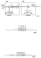
- FIG. 1 shows the series connection of a drop module DM with a known add module AM as a basic circuit diagram. Both modules form an add-drop module.
- a WDM signal WDMS1 in which two or more groups of channels of WDM group signals are interleaved, is fed to input 1 of the drop module DM.
- the drop module serves to decouple the channels shown in FIG. 2 as continuous lines - or a part of these channels - from a group (drop; filter out / branch off).
- Bragg filters 6 to 9 which are tuned or tunable to specific frequencies can be used. These filters should preferably be implemented as fiber Bragg gratings because of their ease of manufacture.
- the first WDM signal WDMS1 is fed to a first connection 3 of a circulator 2 and is output at its second connection 4, at which the series connection of the Bragg filters 6 to 9 is connected. If the wavelength of a WDM channel matches the blocking frequency of the Bragg filter, this channel is reflected and output via the third connection of the circulator in order to be used again by a WDM demultiplexer 10 (a filter arrangement), which acts as a further channel filter Filtered higher blocking attenuation and then to be delivered to one of the outputs 11 to 14.
- FIG. 3 shows the passband areas of a WDM demultiplexer, which are approximately twice as large as the WDM channel filters, for four channels with, for example, a 200 GHz channel spacing.
- the WDM channel filters are tunable and can be detuned that their cutoff frequencies between the WDM channels lying (parking) and therefore no longer have a drop function.
- Another possibility is the filter effect, for example by heating.
- Through the series connection of filters it is possible, for example up to 4 Coupling out drop channels DK1 to DK4 (drop).
- Through an expanded WDM demultiplexer that has more outputs than possible channels to be coupled out can also be provided for example, any 4 of 8 nested channels a channel group.
- an extended one WDM demultiplexers can also be a wavelength converter inserted between the circulator and the WDM demultiplexer which will then indicate the wavelength of the selected channels adapts the filters.
- the add module essentially consists of an optical one Coupler and a WDM multiplexer 16.
- the add module can add 4 channels AK1 to AK4 via inputs 17 to 20 be fed.
- FIG. 4 shows a drop module BDM designed for broadcast operation, which largely corresponds to FIG. 1.
- this contains a splitter 21 which is switched on in the transmission fiber LWL.
- Part of the WDM signal WDMS present at the input of the module is decoupled via the splitter and fed to an arrangement corresponding to the drop module DM.
- Via fixed and / or tunable filters 6, 7, ... individual channels can be coupled out again and output filtered again.
- the energy not reflected by the filters is destroyed in an optical sump, for example an obliquely cut fiber end.
- FIG. 5 shows a corresponding add-drop module BDM1 for decoupling a single channel, which is also generally filtered again in a wavelength demultiplexer.
Landscapes
- Engineering & Computer Science (AREA)
- Computer Networks & Wireless Communication (AREA)
- Signal Processing (AREA)
- Optical Communication System (AREA)
Applications Claiming Priority (2)
| Application Number | Priority Date | Filing Date | Title |
|---|---|---|---|
| DE19938996 | 1999-08-17 | ||
| DE19938996A DE19938996A1 (de) | 1999-08-17 | 1999-08-17 | Anordnung zum Abzweigen von optischen Signalen |
Publications (1)
| Publication Number | Publication Date |
|---|---|
| EP1077552A2 true EP1077552A2 (fr) | 2001-02-21 |
Family
ID=7918685
Family Applications (1)
| Application Number | Title | Priority Date | Filing Date |
|---|---|---|---|
| EP00116903A Withdrawn EP1077552A2 (fr) | 1999-08-17 | 2000-08-04 | Dispositif d'extraction de signaux optiques |
Country Status (2)
| Country | Link |
|---|---|
| EP (1) | EP1077552A2 (fr) |
| DE (1) | DE19938996A1 (fr) |
Cited By (3)
| Publication number | Priority date | Publication date | Assignee | Title |
|---|---|---|---|---|
| EP1267509A1 (fr) * | 2001-06-12 | 2002-12-18 | Alcatel | Procédé d'organisation de canaux de longeurs d'ondes dans un réseau WDM, et hub optique, multiplexeur optique d'insertion/extraction et banc de filtres optique correspondant |
| EP1569369A1 (fr) * | 2004-02-23 | 2005-08-31 | Alcatel | Réseau de transmission optique en anneau |
| EP1503532A3 (fr) * | 2003-07-28 | 2006-08-09 | Fujitsu Limited | Réseau optique avec rejet de bandes partielles et dérivation |
-
1999
- 1999-08-17 DE DE19938996A patent/DE19938996A1/de not_active Withdrawn
-
2000
- 2000-08-04 EP EP00116903A patent/EP1077552A2/fr not_active Withdrawn
Cited By (4)
| Publication number | Priority date | Publication date | Assignee | Title |
|---|---|---|---|---|
| EP1267509A1 (fr) * | 2001-06-12 | 2002-12-18 | Alcatel | Procédé d'organisation de canaux de longeurs d'ondes dans un réseau WDM, et hub optique, multiplexeur optique d'insertion/extraction et banc de filtres optique correspondant |
| EP1503532A3 (fr) * | 2003-07-28 | 2006-08-09 | Fujitsu Limited | Réseau optique avec rejet de bandes partielles et dérivation |
| US7483636B2 (en) | 2003-07-28 | 2009-01-27 | Fujitsu Limited | Optical network with sub-band rejection and bypass |
| EP1569369A1 (fr) * | 2004-02-23 | 2005-08-31 | Alcatel | Réseau de transmission optique en anneau |
Also Published As
| Publication number | Publication date |
|---|---|
| DE19938996A1 (de) | 2001-03-29 |
Similar Documents
| Publication | Publication Date | Title |
|---|---|---|
| DE69620414T2 (de) | Optischer einfügungs- und abtrennmultiplexer | |
| DE60202354T2 (de) | Vorrichtung zum optischen (De-)multiplexen und Verfahren zum (De-)multiplexen von optischen Signalen | |
| DE69432814T2 (de) | Optischer Bandpass-Filter | |
| DE2844776A1 (de) | Sender-multiplexsystem fuer ein bewegliches uebertragungssystem | |
| DE60100036T2 (de) | Bidirektionale optische Übertragung mit zwei Kanalbanden | |
| DE69533566T2 (de) | Frequenzmultiplexierung mittels Mehrphasenfilter und schnellen Fouriertransformationen | |
| EP1079248B1 (fr) | Module d'insertion-extraction-suite reglable | |
| DE2628906C2 (de) | Funkfeld in einer Richtfunkstrecke | |
| DE4411233C1 (de) | Frequenzkanal-Multiplexer bzw. -Demultiplexer | |
| DE19752944A1 (de) | Optisches Wellenlängenfilter und Demultiplexer | |
| EP1077552A2 (fr) | Dispositif d'extraction de signaux optiques | |
| EP1151568B1 (fr) | Noeud de reseau comprenant des modules d'insertion-extraction optiques | |
| EP1602188B1 (fr) | Dispositif d'insertion-extraction et repartiteur pour signaux multiplexes en longueur d'onde | |
| DE19821245C1 (de) | Optischer Multiplexer und optischer Demultiplexer | |
| EP1997345B1 (fr) | Commutateur selectif en longueur d'ondes et procede pour la commutation par canal pour un interrupteur selectif en longueur d'ondes | |
| DE10046585B4 (de) | Modular erweiterbares optisches ADD-DROP-Modul | |
| DE69731906T2 (de) | Modul-Mehrfachkoppler mit aneinandergrenzenden Ausgangssignalen | |
| EP0118577A1 (fr) | Multiplexeur ou démultiplexeur à longueur d'onde en optique intégrée | |
| DE69934058T2 (de) | Vorrichtung zum Ein-Ausfügen eines optischen Wellenlängenmultiplexsignales | |
| DE10300934B4 (de) | Optische Filteranordnung für ein optisches Wellenlängenmultiplex-Übertragungssystem | |
| EP0766358A1 (fr) | Amplificateur à fibre optique pour une multitude de signaux à longueurs d'onde différentes comprenant un démultiplexeur et un multiplexeur | |
| DE102005051292A1 (de) | Add-Drop-Einrichtung für Wellenlängen-Multiplex-Signale | |
| DE19847410A1 (de) | Optisches unidirektionales Ringnetz | |
| DE19530644C1 (de) | Optischer Kanalmultiplexer und/oder -demultiplexer | |
| DE1963422B2 (de) | Verzweigungs- oder synthesegeraet fuer mehrfrequenz-fernmeldesysteme |
Legal Events
| Date | Code | Title | Description |
|---|---|---|---|
| PUAI | Public reference made under article 153(3) epc to a published international application that has entered the european phase |
Free format text: ORIGINAL CODE: 0009012 |
|
| AK | Designated contracting states |
Kind code of ref document: A2 Designated state(s): AT BE CH CY DE DK ES FI FR GB GR IE IT LI LU MC NL PT SE |
|
| AX | Request for extension of the european patent |
Free format text: AL;LT;LV;MK;RO;SI |
|
| STAA | Information on the status of an ep patent application or granted ep patent |
Free format text: STATUS: THE APPLICATION IS DEEMED TO BE WITHDRAWN |
|
| 18D | Application deemed to be withdrawn |
Effective date: 20040301 |