EP1078131B1 - Deckel für eine schachtabdeckung - Google Patents
Deckel für eine schachtabdeckung Download PDFInfo
- Publication number
- EP1078131B1 EP1078131B1 EP99920950A EP99920950A EP1078131B1 EP 1078131 B1 EP1078131 B1 EP 1078131B1 EP 99920950 A EP99920950 A EP 99920950A EP 99920950 A EP99920950 A EP 99920950A EP 1078131 B1 EP1078131 B1 EP 1078131B1
- Authority
- EP
- European Patent Office
- Prior art keywords
- base plate
- access cover
- bars
- cover according
- bar
- Prior art date
- Legal status (The legal status is an assumption and is not a legal conclusion. Google has not performed a legal analysis and makes no representation as to the accuracy of the status listed.)
- Expired - Lifetime
Links
Images


Classifications
-
- E—FIXED CONSTRUCTIONS
- E02—HYDRAULIC ENGINEERING; FOUNDATIONS; SOIL SHIFTING
- E02D—FOUNDATIONS; EXCAVATIONS; EMBANKMENTS; UNDERGROUND OR UNDERWATER STRUCTURES
- E02D29/00—Independent underground or underwater structures; Retaining walls
- E02D29/12—Manhole shafts; Other inspection or access chambers; Accessories therefor
- E02D29/14—Covers for manholes or the like; Frames for covers
Definitions
- This invention relates to access covers, e.g. for manholes, of the kind in which a cover member is removably fitted within a generally rectangular outer frame, the cover member being fabricated as a generally rectangular inner frame fixed to a base plate to provide a space which is subsequently filled (normally on-site) with concrete or other appropriate filling material.
- An access cover of this kind is described and claimed in the specification of my UK Patent No. 2 145 138B.
- the filling for the inner frame is reinforced by bars (e.g. of steel), which are located and held in place within the outer frame by clips prior to introducing the filling material. It has been found that the reinforcement is best formed as a grid, or mesh, with the crossing points fixedly joined together. However, a disadvantage of such a reinforcement arrangement is that the mesh cannot be cut to size and trimmed automatically and without considerable waste and hence is time consuming and expensive to produce.
- An object of this invention is to provide an access cover of the kind discussed above incorporating an alternative reinforcement arrangement which lends itself to automatic manufacture.
- an access cover of the kind referred to above is characterised by a reinforcement arrangement for the inner frame comprising a number of bars fixed to the base plate of said inner frame., each bar comprising sheet material formed into a channel shaped cross-section.
- each bar comprises a bottom web incorporating spaced fixing means for attachment to said base plate and opposed walls which taper outwardly from said web.
- the outer edges of said opposed walls are reinforced by being bent over
- the opposed walls may be formed with rib-like indentations for stiffening the walls and to provide a mechanical bond for said filling material.
- the bars extend parallel to each other and the base plate is provided with respective lines of spaced fixing means for co-operating with said fixing means of the bars and positioned to interlock with the bar fixing means.
- the base plate has a high degree of rigidity sufficient to support the weight of the filling material in its uncured state with a minimum amount of deformation.
- the reinforcement arrangement acts as a composite with the filling material in its cured state to provide an extremely strong and rigid cover member. The reinforcement arrangement thus has a significant advantage over the arrangement used hitherto, in that the clips used in the prior arrangement merely support and position the reinforcement mesh above the base plate and therefor do not provide any significant rigidity to the base plate itself.
- the bars are cut from a strip of steel 1, which is preferably stainless steel so as to avoid corrosion problems in use.
- the cut length is formed with fixing means comprising, in this embodiment, cut-outs 2 spaced along a central longitudinal portion 3 and with two sets of rib-like indentations 4, 5 along longitudinal portions 6,7 on either side of the central portion; the rib-like indentations are pressed out of the plane of the strip 1 as shown at 4a in Figure 1.
- the positioning and orientation of the indentations of each set are chosen to produce a required degree of rigidity in the bar and to provide a mechanical bond for the filling material; in this embodiment the indentations are diagonally opposed as shown at 4a.
- each bar 8 is formed by bending whereby the longitudinal portion 3 provides a central web and the portions 6, 7 provide outwardly tapering, opposed walls.
- the longitudinal outer edges 9, 10 are reinforced by being bent over as shown. It will be appreciated from the foregoing that the bars can be readily formed automatically from strip material using a conventional forming machine and that the finished bars can be designed to provide a required level of strength and rigidity using a minimum amount of material, thereby significantly reducing manufacturing costs compared with the reinforcement mesh previously used.
- the base plate 11 is preferably of the same material as the bars (i.e. stainless steel) also to avoid corrosion problems and comprises a rectangular sheet with co-operating fixing means for the fixing means provided in the bars 8.
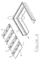
- the co-operating fixing means comprises parallel lines of tongues 12, which are spaced from each other and extend in a common direction to interlock with respective ones of the number of bars 8 required to provide an appropriate degree of rigidity for the particular size of inner frame 13 (see Figure 4) being constructed.
- each line of tongues 12 corresponds to the spacing of the cut-outs 2 of a respective bar 8 and that said bar is interlocked onto the base plate 11 by aligning its cut-outs over said tongues and lateral sliding movement from one side of said base plates, as shown by the arrows in Figure 3.
- the tongues 12 of adjacent lines of tongues extend in opposite directions, as shown, whereby the bars are interlocked alternately by sliding movement from opposite sides of the base plate 11.
- this construction provides a high degree of rigidity over the complete area of the base plate 11, to the extent that transverse bars are not required as in the case of the reinforcement mesh used hitherto.
- the base plate 11, complete with its reinforcement bars 8, is located on horizontal support faces 14 provided by the inner frame 13 for the access cover.
- the individual frame members 15 of the inner frame are of profiled section, preferably of aluminium, and are provided with mitred corners which are fixedly crimped together. After locating the base plate 11 within the inner frame 13 it is fixedly secured by welding, or other appropriate means.
- the bars 8 are then maintained in their interlocked positions by abutting against vertical faces of ribs (16) specifically provided on the profiled frame members 15.
- the complete access cover is designed to be supplied without the filling material, which is normally poured on-site and then finished off with a covering matching the surrounding surface, e.g. tiles, carpet or vinyl floor covering.
Landscapes
- Engineering & Computer Science (AREA)
- Environmental & Geological Engineering (AREA)
- Life Sciences & Earth Sciences (AREA)
- General Life Sciences & Earth Sciences (AREA)
- Mining & Mineral Resources (AREA)
- Paleontology (AREA)
- Civil Engineering (AREA)
- General Engineering & Computer Science (AREA)
- Structural Engineering (AREA)
- Sewage (AREA)
- Underground Structures, Protecting, Testing And Restoring Foundations (AREA)
Claims (8)
- Schachtabdeckung der Art, die ein Deckelelement aufweist, das abnehmbar in einen allgemein rechtwinkligen Außenrahmen eingesetzt wird, wobei das Deckelelement als ein allgemein rechtwinkliger Innenrahmen (13) hergestellt wird, der an einer Grundplatte (11) befestigt ist, wobei der Raum, der dadurch gebildet wird, im wesentlichen mit einem geeigneten Füllmaterial gefüllt wird, dadurch gekennzeichnet, daß für den Innenrahmen (13) eine Verstärkungsanordnung bereitgestellt wird, die eine Reihe von Stäben (8) umfaßt, die an der Grundplatte (11) des Innenrahmens befestigt sind, wobei jeder Stab Plattenmaterial (1) umfaßt, das zu einem U-förmigen Querschnitt geformt worden ist.
- Schachtabdeckung nach Anspruch 1, dadurch gekennzeichnet, daß jeder Stab (8) einen unteren Steg (3), in den eine Reihe von mit Zwischenraum angeordneten Befestigungsmitteln (2) für die Anbringung an der Grundplatte (11) einbezogen ist, und gegenüberliegende Wände (6, 7) aufweist, die von dem Steg konisch nach außen verlaufen.
- Schachtabdeckung nach Anspruch 2, dadurch gekennzeichnet, daß die Außenränder (9, 10) der gegenüberliegenden Wände (6, 7) dadurch verstärkt sind, daß sie umgebogen worden sind.
- Schachtabdeckung nach Anspruch 2 oder Anspruch 3, dadurch gekennzeichnet, daß die gegenüberliegenden Wände (6, 7) mit rippenartigen Vertiefungen (4, 5) gebildet werden, um die Wände zu versteifen und um eine mechanische Bindung für das Füllmaterial bereitzustellen.
- Schachtabdeckung nach einem der vorhergehenden Ansprüche, dadurch gekennzeichnet, daß die Stäbe parallel zueinander verlaufen und die Grundplatte (11) mit entsprechenden parallelen Reihen von mit Zwischenraum angeordneten Befestigungsmitteln (12) für das Zusammenwirken mit den Befestigungsmitteln (2) der Stäbe (8) versehen und für das Einrasten mit den Stab-Befestigungsmitteln angeordnet ist, um dadurch der Grundplatte einen Grad an Steifigkeit zu geben, der ausreicht, um das Gewicht des Füllmaterials zu tragen.
- Schachtabdeckung nach Anspruch 5, dadurch gekennzeichnet, daß die Befestigungsmittel (2, 12) eine mit Zwischenraum angeordnete Reihe von zusammenwirkenden Zungen (12) und Ausschnitten (2) für jeden Stab umfassen, wobei die Anordnung so ist, daß jeder Stab dadurch auf der Grundplatte (11) eingerastet wird, daß die zusammenwirkenden Ausschnitte und Zungen ausgerichtet werden und anschließend eine Gleitbewegung von einer Seite der Grundplatte bereitgestellt wird.
- Schachtabdeckung nach Anspruch 6, dadurch gekennzeichnet, daß abwechselnde Reihen von Zungen (12) in entgegengesetzten Richtungen verlaufen, wodurch die Stäbe (8) wechselweise durch eine Gleitbewegung von gegenüberliegenden Seiten der Grundplatte (11) eingerastet werden.
- Schachtabdeckung nach einem der Ansprüche 5 bis 7, dadurch gekennzeichnet, daß die Reihen der Ausschnitte (2) in den Stäben (8) bereitgestellt werden und die Reihen der Zungen (12) in der Grundplatte (11) bereitgestellt werden.
Applications Claiming Priority (3)
| Application Number | Priority Date | Filing Date | Title |
|---|---|---|---|
| GBGB9809909.6A GB9809909D0 (en) | 1998-05-09 | 1998-05-09 | Access covers for manholes |
| GB9809909 | 1998-05-09 | ||
| PCT/GB1999/001231 WO1999058770A1 (en) | 1998-05-09 | 1999-05-07 | Access covers for manholes |
Publications (2)
| Publication Number | Publication Date |
|---|---|
| EP1078131A1 EP1078131A1 (de) | 2001-02-28 |
| EP1078131B1 true EP1078131B1 (de) | 2002-03-27 |
Family
ID=10831726
Family Applications (1)
| Application Number | Title | Priority Date | Filing Date |
|---|---|---|---|
| EP99920950A Expired - Lifetime EP1078131B1 (de) | 1998-05-09 | 1999-05-07 | Deckel für eine schachtabdeckung |
Country Status (5)
| Country | Link |
|---|---|
| EP (1) | EP1078131B1 (de) |
| AU (1) | AU3833499A (de) |
| DE (1) | DE69901101T2 (de) |
| GB (1) | GB9809909D0 (de) |
| WO (1) | WO1999058770A1 (de) |
Family Cites Families (4)
| Publication number | Priority date | Publication date | Assignee | Title |
|---|---|---|---|---|
| GB902650A (en) * | 1960-08-22 | 1962-08-09 | Broads Mfg Company Ltd | Improvements in manhole or like covers and frames |
| US3975870A (en) * | 1974-09-05 | 1976-08-24 | Hiromitsu Naka | Floor hatch |
| GB2092649B (en) * | 1981-01-23 | 1984-07-18 | Brickhouse Dudley Mfg | Manhole covers |
| GB2145138B (en) | 1983-08-18 | 1986-12-10 | Antony Richard Centa | Manhole access cover |
-
1998
- 1998-05-09 GB GBGB9809909.6A patent/GB9809909D0/en not_active Ceased
-
1999
- 1999-05-07 EP EP99920950A patent/EP1078131B1/de not_active Expired - Lifetime
- 1999-05-07 WO PCT/GB1999/001231 patent/WO1999058770A1/en not_active Ceased
- 1999-05-07 AU AU38334/99A patent/AU3833499A/en not_active Abandoned
- 1999-05-07 DE DE69901101T patent/DE69901101T2/de not_active Expired - Fee Related
Also Published As
| Publication number | Publication date |
|---|---|
| AU3833499A (en) | 1999-11-29 |
| HK1034757A1 (en) | 2001-11-02 |
| GB9809909D0 (en) | 1998-07-08 |
| DE69901101T2 (de) | 2002-09-19 |
| WO1999058770A1 (en) | 1999-11-18 |
| DE69901101D1 (de) | 2002-05-02 |
| EP1078131A1 (de) | 2001-02-28 |
Similar Documents
| Publication | Publication Date | Title |
|---|---|---|
| WO2001003898A1 (en) | Lost mould element for manufacturing reinforced concrete flat slabs | |
| US5561957A (en) | Composite wood-concrete building member | |
| CA2491194C (en) | Floor system with steel joists having openings with edge reinforcements and method | |
| US5595034A (en) | Grid assembly with improved form pan for use in grid reinforced concrete decks and method of manufacturing same | |
| EP0009009B1 (de) | Verfahren zur Herstellung vorgefertigter Platten und räumlicher Elemente für Gebäude und nach diesem Verfahren hergestellte Platten | |
| EP0096118B1 (de) | Gebäude | |
| US5220765A (en) | Space frame structure | |
| KR101447360B1 (ko) | 결합 채널을 이용한 에이엘씨 패널 횡벽 설치방법 | |
| GB2248863A (en) | Concrete floor system | |
| US4689870A (en) | Method of making honeycomb floor panel | |
| US20090100776A1 (en) | Formwork | |
| US3849957A (en) | Reinforced concrete ribbed ceiling | |
| US4594833A (en) | Honeycomb floor panel and the like | |
| EP1078131A1 (de) | Deckel für eine schachtabdeckung | |
| HK1034757B (en) | Access covers for manholes | |
| GB2118989A (en) | Dry-laid floors | |
| AU2004236616A1 (en) | A consumable assembly for forming a concrete wall structure, a concrete wall structure formed with the assembly and a side plate for use in the assembly | |
| KR102755429B1 (ko) | 복합 리브형 데크 거푸집 | |
| JP3754215B2 (ja) | ジベル筋及びこれを用いた半プレキャストコンクリート板 | |
| JP3328213B2 (ja) | 中空スラブ構造体 | |
| AU2021102058A4 (en) | A beam for forming a slab with a settable material and a system of forming a slab of a building with a settable material | |
| KR102280675B1 (ko) | 절곡강판을 이용한 중공pc 바닥판넬 | |
| KR100485474B1 (ko) | 데크패널 및 그 제조방법 | |
| EP0139798A1 (de) | Trockenverlegter Fussboden | |
| JPH0741764Y2 (ja) | 床版構築用型枠 |
Legal Events
| Date | Code | Title | Description |
|---|---|---|---|
| PUAI | Public reference made under article 153(3) epc to a published international application that has entered the european phase |
Free format text: ORIGINAL CODE: 0009012 |
|
| 17P | Request for examination filed |
Effective date: 20001102 |
|
| AK | Designated contracting states |
Kind code of ref document: A1 Designated state(s): DE FR GB |
|
| GRAG | Despatch of communication of intention to grant |
Free format text: ORIGINAL CODE: EPIDOS AGRA |
|
| 17Q | First examination report despatched |
Effective date: 20010711 |
|
| GRAG | Despatch of communication of intention to grant |
Free format text: ORIGINAL CODE: EPIDOS AGRA |
|
| GRAH | Despatch of communication of intention to grant a patent |
Free format text: ORIGINAL CODE: EPIDOS IGRA |
|
| GRAH | Despatch of communication of intention to grant a patent |
Free format text: ORIGINAL CODE: EPIDOS IGRA |
|
| REG | Reference to a national code |
Ref country code: GB Ref legal event code: IF02 |
|
| GRAA | (expected) grant |
Free format text: ORIGINAL CODE: 0009210 |
|
| AK | Designated contracting states |
Kind code of ref document: B1 Designated state(s): DE FR GB |
|
| REF | Corresponds to: |
Ref document number: 69901101 Country of ref document: DE Date of ref document: 20020502 |
|
| ET | Fr: translation filed | ||
| PLBE | No opposition filed within time limit |
Free format text: ORIGINAL CODE: 0009261 |
|
| STAA | Information on the status of an ep patent application or granted ep patent |
Free format text: STATUS: NO OPPOSITION FILED WITHIN TIME LIMIT |
|
| 26N | No opposition filed |
Effective date: 20021230 |
|
| PGFP | Annual fee paid to national office [announced via postgrant information from national office to epo] |
Ref country code: GB Payment date: 20060503 Year of fee payment: 8 |
|
| PGFP | Annual fee paid to national office [announced via postgrant information from national office to epo] |
Ref country code: DE Payment date: 20060508 Year of fee payment: 8 |
|
| PGFP | Annual fee paid to national office [announced via postgrant information from national office to epo] |
Ref country code: FR Payment date: 20060515 Year of fee payment: 8 |
|
| GBPC | Gb: european patent ceased through non-payment of renewal fee |
Effective date: 20070507 |
|
| REG | Reference to a national code |
Ref country code: FR Ref legal event code: ST Effective date: 20080131 |
|
| PG25 | Lapsed in a contracting state [announced via postgrant information from national office to epo] |
Ref country code: DE Free format text: LAPSE BECAUSE OF NON-PAYMENT OF DUE FEES Effective date: 20071201 |
|
| PG25 | Lapsed in a contracting state [announced via postgrant information from national office to epo] |
Ref country code: GB Free format text: LAPSE BECAUSE OF NON-PAYMENT OF DUE FEES Effective date: 20070507 |
|
| PG25 | Lapsed in a contracting state [announced via postgrant information from national office to epo] |
Ref country code: FR Free format text: LAPSE BECAUSE OF NON-PAYMENT OF DUE FEES Effective date: 20070531 |