EP1078342B1 - Logement de camera de surveillance avec unite de montage - Google Patents
Logement de camera de surveillance avec unite de montage Download PDFInfo
- Publication number
- EP1078342B1 EP1078342B1 EP00906197A EP00906197A EP1078342B1 EP 1078342 B1 EP1078342 B1 EP 1078342B1 EP 00906197 A EP00906197 A EP 00906197A EP 00906197 A EP00906197 A EP 00906197A EP 1078342 B1 EP1078342 B1 EP 1078342B1
- Authority
- EP
- European Patent Office
- Prior art keywords
- housing
- radially extending
- surveillance camera
- crown plate
- camera housing
- Prior art date
- Legal status (The legal status is an assumption and is not a legal conclusion. Google has not performed a legal analysis and makes no representation as to the accuracy of the status listed.)
- Expired - Lifetime
Links
Images





Classifications
-
- G—PHYSICS
- G08—SIGNALLING
- G08B—SIGNALLING SYSTEMS, e.g. PERSONAL CALLING SYSTEMS; ORDER TELEGRAPHS; ALARM SYSTEMS
- G08B13/00—Burglar, theft or intruder alarms
- G08B13/18—Actuation by interference with heat, light, or radiation of shorter wavelength; Actuation by intruding sources of heat, light, or radiation of shorter wavelength
- G08B13/189—Actuation by interference with heat, light, or radiation of shorter wavelength; Actuation by intruding sources of heat, light, or radiation of shorter wavelength using passive radiation detection systems
- G08B13/194—Actuation by interference with heat, light, or radiation of shorter wavelength; Actuation by intruding sources of heat, light, or radiation of shorter wavelength using passive radiation detection systems using image scanning and comparing systems
- G08B13/196—Actuation by interference with heat, light, or radiation of shorter wavelength; Actuation by intruding sources of heat, light, or radiation of shorter wavelength using passive radiation detection systems using image scanning and comparing systems using television cameras
- G08B13/19617—Surveillance camera constructional details
- G08B13/19632—Camera support structures, e.g. attachment means, poles
-
- G—PHYSICS
- G08—SIGNALLING
- G08B—SIGNALLING SYSTEMS, e.g. PERSONAL CALLING SYSTEMS; ORDER TELEGRAPHS; ALARM SYSTEMS
- G08B13/00—Burglar, theft or intruder alarms
- G08B13/18—Actuation by interference with heat, light, or radiation of shorter wavelength; Actuation by intruding sources of heat, light, or radiation of shorter wavelength
- G08B13/189—Actuation by interference with heat, light, or radiation of shorter wavelength; Actuation by intruding sources of heat, light, or radiation of shorter wavelength using passive radiation detection systems
- G08B13/194—Actuation by interference with heat, light, or radiation of shorter wavelength; Actuation by intruding sources of heat, light, or radiation of shorter wavelength using passive radiation detection systems using image scanning and comparing systems
- G08B13/196—Actuation by interference with heat, light, or radiation of shorter wavelength; Actuation by intruding sources of heat, light, or radiation of shorter wavelength using passive radiation detection systems using image scanning and comparing systems using television cameras
- G08B13/19617—Surveillance camera constructional details
- G08B13/19619—Details of casing
-
- G—PHYSICS
- G08—SIGNALLING
- G08B—SIGNALLING SYSTEMS, e.g. PERSONAL CALLING SYSTEMS; ORDER TELEGRAPHS; ALARM SYSTEMS
- G08B13/00—Burglar, theft or intruder alarms
- G08B13/18—Actuation by interference with heat, light, or radiation of shorter wavelength; Actuation by intruding sources of heat, light, or radiation of shorter wavelength
- G08B13/189—Actuation by interference with heat, light, or radiation of shorter wavelength; Actuation by intruding sources of heat, light, or radiation of shorter wavelength using passive radiation detection systems
- G08B13/194—Actuation by interference with heat, light, or radiation of shorter wavelength; Actuation by intruding sources of heat, light, or radiation of shorter wavelength using passive radiation detection systems using image scanning and comparing systems
- G08B13/196—Actuation by interference with heat, light, or radiation of shorter wavelength; Actuation by intruding sources of heat, light, or radiation of shorter wavelength using passive radiation detection systems using image scanning and comparing systems using television cameras
- G08B13/19617—Surveillance camera constructional details
- G08B13/1963—Arrangements allowing camera rotation to change view, e.g. pivoting camera, pan-tilt and zoom [PTZ]
Definitions
- This invention relates to the field of surveillance camera housings and specifically for a housing mounting unit which places the interface for the electrical connections between a mount and a surveillance camera at the mechanical interface between the housing and a mount.
- the interface between the mounting unit and the housing must be strong, aesthetically pleasing, and watertight. This requires that the housing be connected to the mounting unit in a separate operation generally using fasteners flattening a gasket to produce the necessary seal.
- the housing subassembly contains unterminated wires extending therein which must be later connected to a surveillance camera by a technically qualified individual.
- the connection requires access inside the housing necessitating a larger housing to allow ingress of the camera. This arrangement thus requires costly installer time, a larger housing, and a field-actuated mechanical and electrical interface device.
- EP 0 544 996 A2 discloses a surveillance assembly in which a camera and a lens assembly is surrounded by a shroud to form an eyeball assembly which is rotatable about a first and second axes and which is enclosed within a housing.
- a camera housing which can be easily coupled to a mount without the need for costly field technicians to install the device.
- a camera housing with a mounting unit which allows for simple engagement of the housing with a mount.
- the installation should preferably be user controlled, inexpensive, reliable, structurally sound, and aesthetically pleasing.
- a camera housing is combined with a mount in a manner that is simple, aesthetically pleasing, yields reliable engagement, and is structurally sound.
- the invention provides a surveillance camera housing as defined by claim 1.
- This aspect yields a structurally strong, aesthetically pleasing, easily installed camera housing mount combination.
- Another aspect of the invention is a method of connecting a surveillance camera housing including a mounting unit, with a mount including a mounting cap, as defined by claim 10.
- a housing 20 is connected to a mounting unit shown generally at 22.
- Fig. 3 details the components of mounting unit 22 with a cut away cross-sectional view of mounting unit 22 taken along the line B-B shown in the plan view of Fig. 2.
- Tapered opening 26 can contain internal threads 27 to mate with an externally threaded pipe mount (not shown).
- Mounting cap 24 further contains inward extensions 46 which extend parallel to a central axis 56 of the frustrum.
- Crown plate 30 has radially extending exterior flanges 32 for engaging with interior flanges 28.
- the underside of crown plate 30 is sealed in a watertight manner to the top of housing 20 with a seal 34.
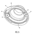
- Seal 34 can be a flat gasket, a plurality of screws 35 (shown in Fig. 6), or any other conventional sealing unit. Access to components inside the housing, such as address switches, can be realized by removing seal 34.
- FIG. 4 there is a cut-away cross-sectional view of mounting unit 22 taken along line D-D shown in the plan view of Fig. 2.
- Electrical connectors 36 are disposed on, and electrically coupled to, an electrical connector plate 38 thereby providing an electrical connection between tapered opening 26 and the interior of housing 20.
- Electrical connector plate 38 is further coupled to crown plate 30 through screws 40.
- a hollow radial gasket 42 having a hollow, bulb-shaped, circumferential edge 44, is disposed on top of crown plate 30.
- radial gasket 42 could also be affixed to mounting cap 24.
- inward extensions 46 deflect circumferential edge 44 downward thereby creating a seal pressure for all elements disposed radially external to circumferential edge 44.
- all elements disposed within the hollow portion of radial gasket 42 are left unsealed and accessible through tapered entry 26.
- the use of a hollow, bulb-shaped circumferential edge 44 allows for significant radial deflection with minimal and equal amounts of both insertion and extraction forces which avoids the need of high cost precision tolerances.
- interior flanges 28 are disposed on approximately half of the circumferential edge of mounting cap 24.
- the other half of the circumferential edge of mounting cap 24 contains voids 50 which exist where interior flanges 28 would have been, and further contains screw receiving portions 52.
- exterior flanges 32 cover approximately half of the circumferential edge of crown plate 30.
- the other half of the circumferential edge of crown plate 30 contains voids 54.
- exterior flanges 32 extend to the furthest position from central axis 56. By placing exterior flanges 32 at this position, two distinct strength factors are realized. First, the circumference of these flanges is larger thereby creating more bearing area to reduce the stress induced upon the flanges themselves. Second, the large off-axis distance allows for more stress to be transmitted through torque loads at the interface between housing 20 and mounting cap 24.
- a surveillance camera (not shown) is placed within housing 22 with all electrical connectors 36 which must be accessible to an installer, being disposed near the hollow portion of radial gasket 42 and thus near the center of crown plate 30.
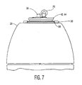
- a safety cable eyehook 70 may be disposed near electrical connectors 36.
- Housing 20, along with mounting unit 22 are engaged with mounting cap 24 by placing exterior flanges 32 in voids 50 and simultaneously placing interior flanges 28 in voids 54. Housing 20 and mounting unit 22 are further lifted so that a horizontal plane defined by exterior flanges 32 is higher than a corresponding horizontal plane defined by interior flanges 28.
- Housing 20 and mounting unit 22 are then rotated a quarter turn about housing 20's long axis thereby placing exterior flanges 32 above interior flanges 28 and allowing exterior flanges 32 to be supported by interior flanges 28 as is shown most clearly in Fig. 3.
- rib extensions 58 are disposed at both ends of exterior flanges 32. At a first end of exterior flange 32, rib extension 58 completely inhibits rotation of housing 20 and mounting unit 22. At a second end of exterior flange 32, rib extension allows rotation of housing 20 and mounting unit 22 only if housing 20 and mounting unit 22 are initially raised vertically. Rib extension 58 thus prevents unintentional disengagement due to applied gravitational forces. Removal of housing 20 requires a user to lift housing 20 vertically and rotate housing 20 about its long axis in a direction opposite that which was used to insert housing 20.
- anti-rotation screws 60 supplement rib extensions 58 by further inhibiting any rotation of housing 20.
- anti-rotation screw 60 is threaded through screw receiving portion 52 in mounting cap 24 into a notch 62 disposed in an exterior portion of crown plate 30.
- anti-rotation screws 60 are mounted generally vertically so as to improve the aesthetics of the apparatus while still maintaining accessibility for an installer.
- Anti-rotation screws 60 are disposed on crown plate 30 at a position which is radially external to radial gasket 42 so that any water seeping through the screw threads will flow through the gap between mounting cap 24 and housing 20 and will not enter the inside of housing 20.
- anti-rotation screws could be replaced with spring-loaded detents (not shown) for effecting the same purpose.
- Mounting cap 24 can be formed as an extension of any mount.
- a wall mount arm extension could terminate in a structure like mounting cap 24.
- the external surfaces on the mounting arm could be further structured to blend with housing 20.
- the mounting cap could further contain a small circumferential step disposed radially upon it to indicate where housing 20 ends and mounting cap 24 begins.
- the mounting unit and the electrical connector near each other, an installer is provided with the ability to quickly and conveniently access and install a surveillance camera housing to a mount. Additionally, minimal stress is placed on the electrical wires, a high level of mechanical strength and reliability are realized, and aesthetics are maintained.
- the camera is hard wired in the factory and so no time-consuming or costly connection device is required during installation. Furthermore, the camera and the housing are all in one subassembly and so the camera is protected during handling.
- the circumferential edge 44 of radial gasket 42 could include a plurality of radially extending protrusions or fingers 64 (like an open bulb) instead of a hollow bulb shape as in Fig. 8A.
- radial gasket 42 could be disposed about crown plate 30 so that circumferential edge 44 is compressed axially instead of radially.
- Radially gasket 42 and inward extension 46 could be replaced by a first labyrinth portion 66 and a second labyrinth portion 68 designed to interlock with each other. Clearly, this labyrinth interlocking would not provide a true seal but the defined tortuous path would discourage ingress of contamination.
- internal surface 48 of mounting cap 24 need not be cylindrical.
- the external surface of crown plate 30 or the internal surface of mounting cap 24 could be tapered to effectuate engagement of the elements.
- Interior flange 28 and exterior flange 32 which provide mating engagement between housing 20 and mounting plate 24 need not be flange shaped. They could, for example, embody keying features wherein a series of protrusions and voids mesh and interlock providing mating ingress and egress in one position and providing support of housing 20 in another position.
- the flanges could also embody a series of protrusions of variable size thereby providing a cam action tightening the mounting cap-housing interface.
- any reference signs placed between parentheses shall not be construed as limiting the claim.
- the wording "comprising” does not exclude the presence of elements or steps other than those listed in a claim.
- the wording "a” or “an” preceding an element does not exclude the presence of a plurality of such elements.
- several of these means can be embodied by one and the same item of hardware.
- a surveillance camera housing contains a crown plate with voids and radially extending flanges which engage corresponding radially extending flanges and voids in a mounting cap.
- a radial gasket is disposed upon the crown plate and electrical connectors are disposed within the radial gasket.
- the flanges of the crown plate are placed within the voids of the mounting cap and the flanges of the mounting cap are placed in the voids of the crown plate.
- the housing is further lifted vertically a horizontal plane defined by the crown plate flanges rises above a horizontal plane defined by the mounting cap flanges.
- the housing is then rotated so that the crown plate flanges rest upon the mounting cap flanges.
Landscapes
- Physics & Mathematics (AREA)
- General Physics & Mathematics (AREA)
- Studio Devices (AREA)
- Accessories Of Cameras (AREA)
Abstract
Claims (11)
- Logement de caméra de surveillance,
comprenant :une unité de monture (22) comportant une plaque de couronne (30) et un capuchon de monture (24), la plaque de couronne (30) comportant une première collerette s'étendant radialement (32) pour s'engager sur une seconde collerette s'étendant radialement (28) du capuchon de monture (24), etun connecteur électrique (36) disposé à l'intérieur de la plaque de couronne (30). - Logement de caméra de surveillance selon la revendication 1,
comprenant en outre
une garniture de joint radiale (42) disposée sur la plaque de couronne (30). - Logement de caméra de surveillance selon la revendication 2,
dans lequel
la garniture radiale (42) comporte un bord circonférentiel en forme de bulbe (44) et un certain nombre de doigts s'étendant radialement (64). - Logement de caméra de surveillance selon la revendication 1,
comprenant en outre
une première partie de labyrinthe (68) disposée sur la plaque de couronne (30) pour s'engager dans une seconde partie de labyrinthe (66) du capuchon de monture (24), ces parties de labyrinthe décourageant la pénétration de produits de contamination dans le logement (20). - Logement de caméra de surveillance selon la revendication 1,
dans lequel
la première collerette s'étendant radialement (32) comprend au moins une première partie de nervure et une seconde partie de nervure (58) pour limiter le mouvement entre la première collerette s'étendant radialement (32) et la seconde collerette s'étendant radialement (28). - Logement de caméra de surveillance selon la revendication 1,
dans lequel
la plaque de couronne (30) comprend en outre un certain nombre d'encoches (62) destinées à recevoir un certain nombre de vis anti-rotation (60), ces vis anti-rotation (60) empêchant tout mouvement entre la première collerette s'étendant radialement (32) et la seconde collerette s'étendant radialement (28). - Logement de caméra de surveillance selon la revendication 1,
dans lequel
les collerettes concrétisent l'une d'une caractéristique de verrouillage et d'une série de saillies de dimensions variables. - Logement de caméra de surveillance selon la revendication 1,
dans lequel
la plaque de couronne (30) comprend en outre un certain nombre de détentes à ressort pour empêcher tout mouvement entre la première collerette s'étendant radialement (32) et la seconde collerette s'étendant radialement (28). - Logement de caméra de surveillance selon la revendication 1,
dans lequel
chacune des première et seconde collerettes s'étendant radialement comprend un certain nombre de collerettes. - Procédé de connexion d'un logement de caméra de surveillance (20) comprenant une unité de monture (22), à une monture comprenant un capuchon de monture (24),
ce procédé comprenant les étapes consistant à :créer une unité de monture (22) munie d'une plaque de couronne (30), cette plaque de couronne comportant une première collerette s'étendant radialement (32),créer un capuchon de monture (24) muni d'une seconde collerette s'étendant radialement (28),disposer des connecteurs électriques (36) dans le logement (20),introduire le logement (20) muni de l'unité de monture (22) dans le capuchon de monture (24) de façon que la première collerette (32) pénètre dans le capuchon de monture (24) dans une position dans laquelle la seconde collerette (28) n'est pas présente (50), et que la seconde collerette (28) pénètre dans le logement (20) dans une position dans laquelle la première collerette (32) n'est pas présente (54), etfaire tourner le logement (20) pour amener ainsi la seconde collerette (28) à être disposée au-dessous de la première collerette (32). - Logement de caméra de surveillance selon la revendication 1,
dans lequel
ce logement de caméra de surveillance est couplé à une monture par l'intermédiaire de l'unité de monture (22), et la seconde collerette s'étendant radialement (32) repose sur la première collerette s'étendant radialement (28).
Applications Claiming Priority (3)
| Application Number | Priority Date | Filing Date | Title |
|---|---|---|---|
| US09/253,081 US6700620B1 (en) | 1999-02-19 | 1999-02-19 | Surveillance camera housing with mounting means |
| US253081 | 1999-02-19 | ||
| PCT/EP2000/000234 WO2000049588A1 (fr) | 1999-02-19 | 2000-01-13 | Logement de camera de surveillance avec unite de montage |
Publications (2)
| Publication Number | Publication Date |
|---|---|
| EP1078342A1 EP1078342A1 (fr) | 2001-02-28 |
| EP1078342B1 true EP1078342B1 (fr) | 2005-08-10 |
Family
ID=22958755
Family Applications (1)
| Application Number | Title | Priority Date | Filing Date |
|---|---|---|---|
| EP00906197A Expired - Lifetime EP1078342B1 (fr) | 1999-02-19 | 2000-01-13 | Logement de camera de surveillance avec unite de montage |
Country Status (5)
| Country | Link |
|---|---|
| US (1) | US6700620B1 (fr) |
| EP (1) | EP1078342B1 (fr) |
| JP (1) | JP4263369B2 (fr) |
| DE (1) | DE60021809T2 (fr) |
| WO (1) | WO2000049588A1 (fr) |
Families Citing this family (12)
| Publication number | Priority date | Publication date | Assignee | Title |
|---|---|---|---|---|
| US7357312B2 (en) | 1998-05-29 | 2008-04-15 | Gangi Frank J | System for associating identification and personal data for multiple magnetic stripe cards or other sources to facilitate a transaction and related methods |
| US20020060745A1 (en) * | 2000-07-28 | 2002-05-23 | Philips Electronics North America Corporation | Outdoor dome |
| USD561804S1 (en) * | 2004-09-08 | 2008-02-12 | Matsushita Electric Industrial Co., Ltd. | Surveillance television camera |
| USD562869S1 (en) * | 2004-09-08 | 2008-02-26 | Matsushita Electric Industrial Co., Ltd. | Surveillance television camera |
| US7217045B2 (en) * | 2005-01-03 | 2007-05-15 | Robert Bosch Gmbh | Connect/disconnect mechanism for a surveillance camera head |
| US20070126871A1 (en) * | 2005-12-06 | 2007-06-07 | Henninger Paul E Iii | Modular surveillance camera system with self-identification capability |
| US20070126872A1 (en) * | 2005-12-06 | 2007-06-07 | Michael Bolotine | Modular surveillance camera system |
| DE102012213196A1 (de) * | 2011-07-28 | 2013-01-31 | Continental Teves Ag & Co. Ohg | Schaltung zum Leiten eines elektrischen Stromes |
| DE202014103541U1 (de) * | 2014-07-30 | 2015-11-02 | Burg-Wächter Kg | Kameraanordnung |
| TWI534385B (zh) * | 2014-10-20 | 2016-05-21 | 晶睿通訊股份有限公司 | 監視器設備 |
| USD836148S1 (en) * | 2016-05-18 | 2018-12-18 | Hanwha Aerospace Co., Ltd. | Surveillance camera |
| JP2024145598A (ja) * | 2023-03-31 | 2024-10-15 | i-PRO株式会社 | 監視カメラ |
Family Cites Families (14)
| Publication number | Priority date | Publication date | Assignee | Title |
|---|---|---|---|---|
| US4019045A (en) * | 1975-08-25 | 1977-04-19 | General Motors Corporation | Socket mounting cap |
| US4928202A (en) * | 1988-12-12 | 1990-05-22 | Stanley Aviation Corporation | Coupler with combination locking and bonding ring |
| US5251118A (en) * | 1991-08-16 | 1993-10-05 | Devine Lighting, Inc. | Modular lighting system and method |
| EP0544996B1 (fr) * | 1991-12-04 | 1996-06-12 | Sensormatic Electronics Corporation | Dispositif de surveillance avec un assemblage sphérique et un ensemble à chariot pivotable |
| US5299952A (en) * | 1992-07-27 | 1994-04-05 | Hinds Jr Richard A | Overhead electrical fixture and portable lowering tool therefor |
| US5486989A (en) * | 1993-11-12 | 1996-01-23 | Kim Lighting, Inc. | Luminaire with modular louver shields |
| JPH07162723A (ja) * | 1993-12-10 | 1995-06-23 | Atsumi Electron Corp Ltd | 監視カメラ |
| DE4405626C1 (de) | 1994-02-22 | 1995-02-02 | Hartig E Videor Tech | Schutzgehäuse für optische Geräte |
| US5535109A (en) * | 1994-04-29 | 1996-07-09 | Thomas & Betts Corporation | Quartz halogen flood light assembly having improved housing |
| SE515350C2 (sv) * | 1995-04-11 | 2001-07-16 | Ericsson Telefon Ab L M | Anordning för montering av en basstation |
| US5689304A (en) * | 1996-03-04 | 1997-11-18 | Philips Electronic North America Corporation | Indoor/outdoor surveillance housing |
| US5803590A (en) * | 1996-03-08 | 1998-09-08 | Thomas & Betts Corporation | Roadway luminaire |
| US5718602A (en) | 1996-07-31 | 1998-02-17 | Duraline, A Division Of J.B. Nottingham Co., Inc. | Suspension connector assembly for multiple pin electrical connector |
| US6061087A (en) * | 1998-07-16 | 2000-05-09 | Sensormatic Electronics Corporation | Outdoor enclosure for video surveillance system |
-
1999
- 1999-02-19 US US09/253,081 patent/US6700620B1/en not_active Expired - Lifetime
-
2000
- 2000-01-13 WO PCT/EP2000/000234 patent/WO2000049588A1/fr not_active Ceased
- 2000-01-13 JP JP2000600251A patent/JP4263369B2/ja not_active Expired - Fee Related
- 2000-01-13 DE DE60021809T patent/DE60021809T2/de not_active Expired - Lifetime
- 2000-01-13 EP EP00906197A patent/EP1078342B1/fr not_active Expired - Lifetime
Also Published As
| Publication number | Publication date |
|---|---|
| US6700620B1 (en) | 2004-03-02 |
| DE60021809T2 (de) | 2006-06-08 |
| DE60021809D1 (de) | 2005-09-15 |
| EP1078342A1 (fr) | 2001-02-28 |
| JP4263369B2 (ja) | 2009-05-13 |
| JP2002537707A (ja) | 2002-11-05 |
| WO2000049588A1 (fr) | 2000-08-24 |
Similar Documents
| Publication | Publication Date | Title |
|---|---|---|
| EP1078342B1 (fr) | Logement de camera de surveillance avec unite de montage | |
| US6491546B1 (en) | Locking F terminator for coaxial cable systems | |
| US8158884B2 (en) | Angled slots for installation of outdoor metallic boxes | |
| CA2175425C (fr) | Capuchon avec joint d'etancheite pour boitier de connecteur electrique | |
| US4851725A (en) | Terminal block assembly for a leadless motor | |
| US5941669A (en) | Jack-out captivated screw | |
| US6070835A (en) | Ball-compression grommet | |
| JPH09219239A (ja) | 電気コネクタ・プラグ | |
| WO2018089226A1 (fr) | Borne de connecteur et son procédé d'assemblage | |
| EP0779681B1 (fr) | Boíti de terminaux en plastique | |
| CA2080389C (fr) | Couvercle protecteur permanent | |
| US4726788A (en) | Electrical receptacle | |
| US5004942A (en) | Power and control chamber for dynamoelectric machines | |
| JPH09331181A (ja) | 電子機器筐体の締結構造 | |
| US20260066638A1 (en) | Waterproof cable gland | |
| CA2325912C (fr) | Bornier encastre hermetique | |
| US4723823A (en) | Night Light | |
| JP2570618B2 (ja) | 屋外用通信装置の構造 | |
| WO2020197440A1 (fr) | Boîtier de montage universel pour caméra vidéo | |
| KR200190661Y1 (ko) | 돔형상 감시 카메라용 하우징 | |
| CN214960605U (zh) | 一种电子设备 | |
| MY119470A (en) | Capacitor cover | |
| US4921446A (en) | Telephone jack apparatus | |
| EP0736231B1 (fr) | Procede et dispositif destines a un coffret de racordement electrique | |
| CA2027404C (fr) | Module de commande et d'alimentation pour machines dynamoelectriques |
Legal Events
| Date | Code | Title | Description |
|---|---|---|---|
| PUAI | Public reference made under article 153(3) epc to a published international application that has entered the european phase |
Free format text: ORIGINAL CODE: 0009012 |
|
| AK | Designated contracting states |
Kind code of ref document: A1 Designated state(s): AT BE CH CY DE DK ES FI FR GB GR IE IT LI LU MC NL PT SE |
|
| 17P | Request for examination filed |
Effective date: 20010226 |
|
| 17Q | First examination report despatched |
Effective date: 20021213 |
|
| RAP1 | Party data changed (applicant data changed or rights of an application transferred) |
Owner name: ROBERT BOSCH GMBH |
|
| RBV | Designated contracting states (corrected) |
Designated state(s): DE FR GB NL |
|
| GRAP | Despatch of communication of intention to grant a patent |
Free format text: ORIGINAL CODE: EPIDOSNIGR1 |
|
| GRAS | Grant fee paid |
Free format text: ORIGINAL CODE: EPIDOSNIGR3 |
|
| GRAA | (expected) grant |
Free format text: ORIGINAL CODE: 0009210 |
|
| AK | Designated contracting states |
Kind code of ref document: B1 Designated state(s): DE FR GB NL |
|
| REG | Reference to a national code |
Ref country code: GB Ref legal event code: FG4D |
|
| REF | Corresponds to: |
Ref document number: 60021809 Country of ref document: DE Date of ref document: 20050915 Kind code of ref document: P |
|
| ET | Fr: translation filed | ||
| PLBE | No opposition filed within time limit |
Free format text: ORIGINAL CODE: 0009261 |
|
| STAA | Information on the status of an ep patent application or granted ep patent |
Free format text: STATUS: NO OPPOSITION FILED WITHIN TIME LIMIT |
|
| 26N | No opposition filed |
Effective date: 20060511 |
|
| PGFP | Annual fee paid to national office [announced via postgrant information from national office to epo] |
Ref country code: NL Payment date: 20140122 Year of fee payment: 15 |
|
| PGFP | Annual fee paid to national office [announced via postgrant information from national office to epo] |
Ref country code: FR Payment date: 20140124 Year of fee payment: 15 |
|
| PGFP | Annual fee paid to national office [announced via postgrant information from national office to epo] |
Ref country code: GB Payment date: 20140123 Year of fee payment: 15 |
|
| REG | Reference to a national code |
Ref country code: NL Ref legal event code: V1 Effective date: 20150801 |
|
| GBPC | Gb: european patent ceased through non-payment of renewal fee |
Effective date: 20150113 |
|
| PG25 | Lapsed in a contracting state [announced via postgrant information from national office to epo] |
Ref country code: NL Free format text: LAPSE BECAUSE OF NON-PAYMENT OF DUE FEES Effective date: 20150801 |
|
| PG25 | Lapsed in a contracting state [announced via postgrant information from national office to epo] |
Ref country code: GB Free format text: LAPSE BECAUSE OF NON-PAYMENT OF DUE FEES Effective date: 20150113 |
|
| REG | Reference to a national code |
Ref country code: FR Ref legal event code: ST Effective date: 20150930 |
|
| PG25 | Lapsed in a contracting state [announced via postgrant information from national office to epo] |
Ref country code: FR Free format text: LAPSE BECAUSE OF NON-PAYMENT OF DUE FEES Effective date: 20150202 |
|
| PGFP | Annual fee paid to national office [announced via postgrant information from national office to epo] |
Ref country code: DE Payment date: 20190326 Year of fee payment: 20 |
|
| REG | Reference to a national code |
Ref country code: DE Ref legal event code: R071 Ref document number: 60021809 Country of ref document: DE |