EP1078521B1 - Verfahren und vorrichtung zur erhöhung der kapazität und verbesserung der übertragungsleistung in kabelfernsehnetzwerken - Google Patents
Verfahren und vorrichtung zur erhöhung der kapazität und verbesserung der übertragungsleistung in kabelfernsehnetzwerken Download PDFInfo
- Publication number
- EP1078521B1 EP1078521B1 EP99917042A EP99917042A EP1078521B1 EP 1078521 B1 EP1078521 B1 EP 1078521B1 EP 99917042 A EP99917042 A EP 99917042A EP 99917042 A EP99917042 A EP 99917042A EP 1078521 B1 EP1078521 B1 EP 1078521B1
- Authority
- EP
- European Patent Office
- Prior art keywords
- transmission
- symbol
- combining
- transmission channels
- arrangement
- Prior art date
- Legal status (The legal status is an assumption and is not a legal conclusion. Google has not performed a legal analysis and makes no representation as to the accuracy of the status listed.)
- Expired - Lifetime
Links
- 238000004891 communication Methods 0.000 title claims abstract description 28
- 238000000034 method Methods 0.000 title claims abstract description 28
- 230000005540 biological transmission Effects 0.000 claims abstract description 33
- 238000013507 mapping Methods 0.000 claims description 8
- 238000011144 upstream manufacturing Methods 0.000 description 14
- 230000003044 adaptive effect Effects 0.000 description 9
- 238000013459 approach Methods 0.000 description 6
- 238000007493 shaping process Methods 0.000 description 5
- 230000003595 spectral effect Effects 0.000 description 5
- 238000012937 correction Methods 0.000 description 4
- 238000010586 diagram Methods 0.000 description 4
- 230000006870 function Effects 0.000 description 4
- 238000012986 modification Methods 0.000 description 4
- 230000004048 modification Effects 0.000 description 4
- 238000007476 Maximum Likelihood Methods 0.000 description 3
- 230000006978 adaptation Effects 0.000 description 3
- 230000008859 change Effects 0.000 description 2
- 230000001186 cumulative effect Effects 0.000 description 2
- 239000000654 additive Substances 0.000 description 1
- 230000000996 additive effect Effects 0.000 description 1
- 230000002457 bidirectional effect Effects 0.000 description 1
- 238000004364 calculation method Methods 0.000 description 1
- 239000000969 carrier Substances 0.000 description 1
- 238000006243 chemical reaction Methods 0.000 description 1
- 230000006735 deficit Effects 0.000 description 1
- 230000003111 delayed effect Effects 0.000 description 1
- 230000001419 dependent effect Effects 0.000 description 1
- 238000001514 detection method Methods 0.000 description 1
- 230000000694 effects Effects 0.000 description 1
- 230000008030 elimination Effects 0.000 description 1
- 238000003379 elimination reaction Methods 0.000 description 1
- 238000001914 filtration Methods 0.000 description 1
- 230000001771 impaired effect Effects 0.000 description 1
- 230000002452 interceptive effect Effects 0.000 description 1
- 239000000463 material Substances 0.000 description 1
- 230000010363 phase shift Effects 0.000 description 1
- 238000012545 processing Methods 0.000 description 1
- 230000009467 reduction Effects 0.000 description 1
- 230000004044 response Effects 0.000 description 1
- 230000008054 signal transmission Effects 0.000 description 1
- 238000001228 spectrum Methods 0.000 description 1
- 238000012549 training Methods 0.000 description 1
- 238000012546 transfer Methods 0.000 description 1
- 230000007704 transition Effects 0.000 description 1
Images




Classifications
-
- H—ELECTRICITY
- H04—ELECTRIC COMMUNICATION TECHNIQUE
- H04N—PICTORIAL COMMUNICATION, e.g. TELEVISION
- H04N21/00—Selective content distribution, e.g. interactive television or video on demand [VOD]
- H04N21/20—Servers specifically adapted for the distribution of content, e.g. VOD servers; Operations thereof
- H04N21/23—Processing of content or additional data; Elementary server operations; Server middleware
- H04N21/238—Interfacing the downstream path of the transmission network, e.g. adapting the transmission rate of a video stream to network bandwidth; Processing of multiplex streams
- H04N21/2383—Channel coding or modulation of digital bit-stream, e.g. QPSK modulation
-
- H—ELECTRICITY
- H04—ELECTRIC COMMUNICATION TECHNIQUE
- H04N—PICTORIAL COMMUNICATION, e.g. TELEVISION
- H04N21/00—Selective content distribution, e.g. interactive television or video on demand [VOD]
- H04N21/40—Client devices specifically adapted for the reception of or interaction with content, e.g. set-top-box [STB]; Operations thereof
- H04N21/43—Processing of content or additional data, e.g. demultiplexing additional data from a digital video stream; Elementary client operations, e.g. monitoring of home network or synchronising decoder's clock; Client middleware
- H04N21/438—Interfacing the downstream path of the transmission network originating from a server, e.g. retrieving encoded video stream packets from an IP network
- H04N21/4382—Demodulation or channel decoding, e.g. QPSK demodulation
-
- H—ELECTRICITY
- H04—ELECTRIC COMMUNICATION TECHNIQUE
- H04N—PICTORIAL COMMUNICATION, e.g. TELEVISION
- H04N7/00—Television systems
- H04N7/10—Adaptations for transmission by electrical cable
- H04N7/102—Circuits therefor, e.g. noise reducers, equalisers, amplifiers
Definitions
- the present invention relates generally to communication methods and systems and in particular to communication methods and systems implemented using CATV (Cable Television) systems.
- Cable television (CATV) systems were originally intended to deliver analog television signals to homes in an essentially unidirectional manner.
- the coaxial cable used to carry these signals can support bidirectional transmission of signals, i.e ., transmission both to and from the home.
- cable television companies have begun to provide data communications services to meet consumers' growing demand for high speed data transmission over computer networks, such as the Internet.
- Cable modems have been developed to convert digital data to a modulated radio frequency (RF) signal, and vice versa, for transmission on a CATV system. This conversion is performed both by a cable modem at the subscriber's home and, on the other end, by headend equipment handling multiple subscribers. Thus, the subscriber receives data from a computer network using a downstream channel and transmits data to the network using an upstream channel.
- RF radio frequency
- the present invention can be implemented in full compliance with current network specifications and/or on top of the existing specifications in a manner that enables co-existence of advanced modems designed according to the present invention with current modems.
- the present invention is applicable to a variety of communications networks operating over a cable television (CATV) infrastructure.
- CATV cable television
- channel throughput and communications robustness are increased in the upstream or return channel of a CATV network.
- a filter arrangement is used to reduce interference between adjacent frequency channels, facilitating the use of a frequency grid characterized by reduced channel spacing.
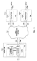
- Figure 1 depicts a CATV digital communication system embodying the present invention and operating according to the MCNS specification.
- the system includes one or more cable modems (CMs) 101a, 101b and a CATV transmission medium 102.
- CMs cable modems
- FIG. 1 depicts two CMs, a greater or lesser number of CMs can be present in the system.
- a cable modem terminating system (CMTS) 103 which is part of CATV head-end equipment 104, is present at the other side of the network.
- Information is transmitted from the CMTS 103 to the CMs 101 using a downstream channel 105, and from the CMs 101 to the CMTS 103 using an upstream channel 106.
- the CMs 101a, 101b include upstream transmitters 107a, 107b that receive input data 108a, 108b and transmit the input data 108a, 108b using a Quadrature Phase Shift Keyring/Quadrature Amplitude Modulation (QPSK/16QAM) modulation scheme with a configurable transmission pulse, pre-equalizer parameters, power level, carrier frequency, symbol clock, and Reed-Solomon forward error correction (FEC) code parameters.
- QPSK/16QAM Quadrature Phase Shift Keyring/Quadrature Amplitude Modulation
- FEC Reed-Solomon forward error correction
- Transmission is performed in a burst mode frequency/time division multiplexing access (FDMA/TDMA) scheme in which each CM 101 transmits requests for bandwidth allocation, and in which a channel allocator 109 sends control messages to the CMs 101 via the downstream channel 105, indicating the time period in which the addressed CM 101 can transmit.
- the CM 101 is capable of modifying its signal parameters, including transmission power, carrier frequency, transmission pulse, and pre-equalizer parameters, according to these control messages from the channel allocator 109.
- the CMTS 103 includes a receiver 110 and the channel allocator 109.
- the receiver 110 detects the information bits fed into the inputs 108a, 108b of the upstream transmitters 107a, 107b.
- the receiver 110 estimates the parameters of the received signals, and outputs these parameters to the channel allocator 109.
- the channel allocator 109 then allocates frequency ranges and configures transmission parameters for the individual CMs 101 in a manner that will make efficient use of the channel bandwidth and that will enable the receiver to detect the signals properly.
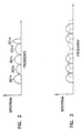
- Figure 2 depicts a frequency constellation of a CATV network operative according to the MCNS specification.
- Signals 201a-201c have the same nominal symbol rate, while signal 201d has a larger symbol rate, and signal 201e has a lower symbol rate.
- the nominal bandwidth of each signal 201a-201e is 1.25 times its respective symbol rate.
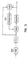
- Figure 3 depicts an example of a reduced channel spacing frequency grid with which the present invention can be used.
- the channel spacing is less than the signal bandwidth, which is 1.25 times the symbol rate of the signals.
- Such a system uses overlapped transmission scheme, such as that disclosed in U.S. Patent 5,710,797, issued on January 20, 1998, assigned to the instant assignee, and entitled METHOD AND APPARATUS FOR DIGITAL COMMUNICATION IN THE PRESENCE OF CLOSELY SPACED ADJACENT CHANNELS, the disclosure of which is hereby incorporated by reference in its entirety.
- the apparatus of Figure 4 includes a transmitter 401 that transmits a digital communication signal 402 through an upstream channel 403.
- the transmitter 401 comprises an encoder 404, a transmission filter 405, and a modulator 406.
- the transmission filter 405 comprises a cascade of a spectral shaping filter 407, a square-root raised cosine filter 408, a fixed shaping filter 409, and a trained pre-equalizer 410.
- This transmission structure may be supported by the current MCNS specification, and therefore may be supported by current MCNS implementations.
- the encoder 404 can include any Forward Error Correction (FEC) code, such as Reed-Solomon encoding.
- FEC Forward Error Correction
- the encoder 404 optionally uses an interleaver within the packet in order to counteract impulse/burst noise.
- Using an interleaver in this manner involves modifications that may not be consistent with existing DOCSIS specifications.
- Alternate signal constellations can be used instead of those specified in the MCNS specification. Examples of such alternate signal constellations include, but are not limited to, pi/4-QPSK, offset-QPSK, 8PSK, 32QAM, 64QAM, 128QAM, and 256QAM.
- the choice of a particular signal constellation is dependent on channel conditions.
- Tomlinson precoding can also be used to avoid a DFE at the receiver 411, but this technique also involves modifications that may not be consistent with existing DOCSIS specifications.
- the spectral shaping filter 407 comprises a duo-path filter (1+ ⁇ z -N , where ⁇ can be a complex number) or any other pre-equalizer that can be used to achieve an approximation to the water-pouring spectral density in conjunction with a DFE receiver, e.g. (1+e -j ⁇ 0 z -1 ) for elimination of narrow-band interference at ⁇ 0 .
- the purpose of the shaping filters 407, 408, and 409 is to reduce adjacent channel interference (ACI) to facilitate the use of a frequency grid characterized by reduced channel spacing.
- ACI adjacent channel interference
- the fixed shaping filter 409 is designed for a more or less known level of signal-to-noise (SNR) ratio and Signal-to-Interferencc (C/I) ratio, and may be loaded during ranging when the C/I and SNR are assessed.
- the trained pre-equalizer 410 performs essentially the inverse l/H of the transfer function H of the upstream channel 403 and is trained at the receiver 411, where the parameters describing the upstream channel 403 are transmitted to the CM 101 through a downstream channel 105 of Figure 1.
- the transmitted signal 402 is impaired by the linear distortion H of the upstream channel 403, by non-linear distortions, and by additive noise sources, including ingress noise and adjacent channel interference.
- the effects of ingress noise and adjacent channel interference are conceptually illustrated in Figure 4 as summing blocks 412 and 413, respectively.
- MMF modified matched filter
- the MMF filter 414 can be loaded from a table according to the estimated C/I and SNR. It should be noted that the pre-calculated filter 416 can be jointly designed with the transmission filter 405 to improve the overall SNR and C/I at the receiver 411.
- the output of the MMF 414 is provided to an adaptive equalizer 417, followed by a decoder 418, which may include additional filtering, a Viterbi detector, and a FEC decoder.
- the MMF 414 can be designed to have low side lobes in the time domain. This is a deviation from an ideal square-root raised-cosine pulse. This deviation might be compensated for by the pre-equalizer 410.
- the reduction in side lobes in the time domain can also prevent the propagation of an impulse noise to symbols that were not originally hit by the impulse.
- FIG 8 depicts an example implementation of an analog front end 420.
- This implementation includes a filter bank 801 of band pass filters (BPFs) 801a, 801b,..., 801n.
- BPFs band pass filters
- Each BPF 801 is centered around a different frequency.
- the output of the BPFs 801, denoted in Figure 8 with reference numerals 804a, 804b, ..., 804n, is input into an analog multiplexer 802.
- Sample rate logic 815 generates a select signal 803 as a function of the center frequency.
- the select signal 803 selects which of the BPF outputs 804 is coupled to an output 805 of the multiplexer 802.
- a parameter also generated by the sample rate logic 815 as a function of the center frequency and denoted with reference numeral 806, defines the sample rate of an analog to digital converter (ADC) 809 and is provided by a clock generator 810.
- the sample rate can be smaller than the Nyquist rate and can be chosen such that deliberate aliasing will shift the center frequency of the desired signal from its original frequency , which can be greater than , to a new frequency , such that F cb is less than F .
- deliberate aliasing facilitates the use of discrete ADC components to sample signals having a frequency greater than half the frequency of the ADC.
- the sample rate logic 815 also provides a spectrum inversion indication 820 to the digital receiver 808 to indicate that undersampling has occurred.
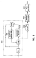
- the adaptive equalizer of Figure 5 is an adaptive Decision Feedback Equalizer (DFE) operating in a noise prediction configuration 501, and it may be preceded by an adaptive FSE 502.
- DFE Decision Feedback Equalizer
- the adaptive FSE 502 the magnitude of the DFE taps can be reduced using tap leakage procedures, thus reducing DFE error propagation.
- the adaptive FSE only can be used, completely avoiding the DFE.
- the equalizer taps arc modified by a Linear Mean Square (LMS) approach. It can be trained during the ranging phase of the CMTS and/or pre-loaded using prior knowledge of channel spacing, and perhaps C/I and SNR.
- LMS Linear Mean Square
- Figure 6 depicts the structure of the decoder when a duo-path pulse 1+ ⁇ z -N , where ⁇ can be a complex number, is used.
- An equalizer 601 is adjusted to achieve a sum of two symbols at its output.
- the output of the equalizer passes through a 1+ ⁇ z -N filter 602, and then goes to a Viterbi detector 603.
- the encoder output 419 in Figure 4 is QPSK symbols ⁇ I ⁇
- the modified slicer 604 of the DFE searches for constellation points I+jQ, where I and Q can have values of 2, 0, and -2.
- the adaptive DFE 605 is trained to minimize the error between the slicer input and the slicer output.
- the complexity of the Viterbi is 4 states and 16 branches per QPSK symbol and 16 states and 256 branches in 16QAM.
- a reduced 16QAM version of 4 states and 16 branches per symbol can be used.
- advance equalization techniques such as a maximum likelihood sequence estimator (MLSE) can be used.
- MSE maximum likelihood sequence estimator
- the idea here is to implement noise prediction and compensation of deliberate ISI due to transmission pulse using a reduced Viterbi equalizer.
- the FEC decoder 606 can be implemented using a conventional Reed-Solomon decoder, assuming this is the code being used in the system.
- a conventional Reed-Solomon decoder assuming this is the code being used in the system.
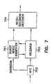
- the burst noise identifier 701 identifies an exceptional data point based on inputs from an Analog Front End (AFE) 702 and a QPSK/16QAM receiver 703 and analyzes the presence and the length of noise burst.
- the Reed-Solomon decoder 704 uses erasures for the data bytes that are suspected to be affected by noise.
- the exceptional data points are detected by either saturations or very large values of the data at the signal path ( e.g ., at the slicer input), a sequence of large error values at the slicer, or yielding of different symbol decisions for the two signals in retransmission mode.
- the receiver has a state machine that estimates burst duration according to the indication of exceptional data points and puts the Reed-Solomon decoder in an erasure mode during the burst. In addition, the receiver performs clipping of signals with exceptionally large magnitudes.
- the present invention can be used in conjunction with reduced spaced signal constellations, such as that depicted in Figure 3, by following the procedures described in U.S. Patent 5,710,797.
- the algorithm may iterate as follows. For a set of overlapping signals, the previously processed signal is subtracted from the received signal. A signal is then detected using the receiver 410 and is remodulated. The algorithm should start with the signal having the best C/I and SNR, which is typically the strongest signal, or a signal that has only one overlapping ACI, rather than two.
- Pairs of severely interfering signals may be jointly detected using an encoded joint maximum likelihood approach, as part of the iterations of a method, the general procedure of which is outlined in U.S. Patent 5,710,797,
- the joint maximum likelihood procedure involves a Viterbi-like algorithm for which a trellis diagram with a branch metric is defined.
- the complexity of such an approach based on a memory constraint of three symbols for each signal, is 16 states and 256 branches per symbol with QSPK and 256 states and 64K branches per symbol in 16QAM.
- the number of transitions can be significantly reduced using a reduced state Viterbi algorithm, e.g ., by discarding states in the trellis diagram that are unlikely for the current signal sample.
- the algorithm selects a survivor path for each of the remaining new states based on the cumulative metric for all possible paths entering the new state from the previous states, followed by the selection of the leading path, and detection of the information bits.
- the algorithm then discards unlikely new states based on the cumulative metrics.
- the present invention can also be used in conjunction with a frequency hopping scheme, using joint frequency/time axis forward error correction and interleaving.
- the receiver 411 makes use of a preamble field in a data packet.
- the preamble should be longer than the duration of the longest error burst that can be recovered by the receiver (i.e ., at least 2t bytes if Reed-Solomon block code (N-t,N) is used, where N is the block size.
- N-t,N Reed-Solomon block code
- the preamble is split into sections, and the receiver identifies sections that are noisy, for example, according to the residual error between the incoming signal and the expected signal according to the known training data and estimated parameters. Sections that are noisy due to impulse or burst noise are neglected.
- the packet structure PDDDPDDDD...D may be used, where P is a preamble section and D is a data section. The distance between P sections will be larger then the maximum burst length that can be received.
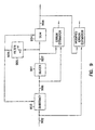
- Figure 9 depicts a modified slicer structure that can be used in connection with the communication apparatus of Figure 4.
- a slicer 901 produces an estimate 902 of the original transmitted symbol 419 of Figure 4.
- This estimate is filtered by a digital filter whose response is ⁇ Z -n , that is, delayed by n taps and multiplied by ⁇ , where ⁇ can be a complex number.
- An output 909 of the filter 905 is subtracted from the next input sample 902 by a subtractor 903 to generate a slicer input 906.
- the output 909 is also summed with a slicer output 907 by a summer 904 to generate a modified slicer output 908.
- such an estimate can be calculated by subtracting the slicer output 907 from the slicer input 906 or by subtracting the modified slicer output 908 from the estimate 902. The latter calculation method realizes improved robustness for error propagation.
- channel throughput and communications robustness are increased using re-transmission techniques and/or diversity techniques. These techniques arc particularly useful when the receiver is incapable of detecting the transmitted data from a single transmission.
- MCNS channels e.g ., different time slots or different carrier frequencies.
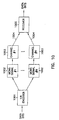
- Figure 10 depicts a general scheme that utilizes diversity and/or retransmission techniques over different MCNS channels according to this embodiment of the present invention.
- a 1:N rate encoder 1001 reproduces the current symbol or the current FEC block N times. Each reproduced symbol or block is transmitted using N MCNS signals 1002 to be communicated to the CMTS 103 of Figure 1 over N different channels 1003. It will be appreciated that the N channels represent physical (e.g., different carriers) and/or logical channels and can overlap in frequency.
- Outputs 1004 of the N channels are provided to a receiver 1005, which performs weighted soft-combining of the received signals 1004.
- the soft-combining comprises Mean Squared Error (MSE) estimation as well as identification of burst noise within the packet, followed by weighted or selective combining, as appropriate.
- the receiver can also incorporate joint equalization of the received signals.
- MSE Mean Squared Error
- the system in Figure 10 can also be interpreted as a retransmission technique in which the first MCNS signal transmitted over the first channel is the original message and all subsequent messages are requested by the CMTS 103 of Figure 1 one, or several, at a time to be retransmitted.
- a soft-combining method is applied to all the received messages.
- a retransmission request can be sent from the CMTS 103 to the CM 101 of Figure 1 via the downstream channel 105 only if a Reed-Solomon block is received incorrectly. If a Reed-Solomon block is received incorrectly, then instead of requesting retransmission, the CMTS 103 tells the CM 101 what it received, so that the CM 101 can send to the CMTS 103 a short correction message rather than sending the whole packet again. For example, the CMTS 103 may send back to the CM 101 an indication of the quality level of the detected symbols or the detected symbols themselves. Since the downstream channel 105 is much wider and more reliable than the upstream channel 106, this approach may be preferable.
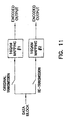
- Figure 11 depicts a particular retransmission scheme in which a different mapping for 16QAM is used for the retransmission.
- Two symbol mapping schemes are illustrated in Figures 12A-12B, in which A1, A2, A3, A4, B1, B2, B3, B4, C1, C2, C3, C4, D1, D2, D3, and D4 represent the sixteen combinations of four bits.
- Figure 13 depicts a signal diversity system.
- two information bits [b1(n) b2(n)], denoted by reference numeral 1301, per symbol are transmitted.
- the symbols are 16QAM and are mapped using a signal mapping block 1302 as a function of [b1(n) b2(n) b1(n-D) b2(n-D)], where D is a delay introduced by a delay block 1303.
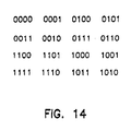
- Figure 14 depicts an example mapping scheme.
- bursts of length D symbols can be recovered.
- the carrier frequency may change between two transmissions of the same data. This change in carrier frequency can be used to protect from narrow band interference.
Landscapes
- Engineering & Computer Science (AREA)
- Multimedia (AREA)
- Signal Processing (AREA)
- Digital Transmission Methods That Use Modulated Carrier Waves (AREA)
- Cable Transmission Systems, Equalization Of Radio And Reduction Of Echo (AREA)
- Detection And Prevention Of Errors In Transmission (AREA)
Claims (8)
- Kommunikationseinrichtung zum Übermitteln eines Datensignals unter Verwendung eines Kabelfernseh-Übertragungsmediums, wobei die Kommunikationseinrichtung aufweist:einen 1 : N-Ratencodierer (1001), der mit einem Eingangsdatenstrom gekoppelt ist und dafür konfiguriert ist, ein durch ein Segment des Eingangsdatenstroms repräsentiertes Symbol oder einen dadurch repräsentierten FEC-Block N mal zu reproduzieren,eine Übertragungseinrichtung, die dafür konfiguriert ist, mehrere Ausgaben (1004) zu verwenden, um jedes reproduzierte Symbol oder jeden reproduzierten FEC-Block unter Verwendung eines gesonderten Übertragungskanals (1003) zu übertragen, undeinen Empfänger (1005), der mit den Ausgaben der Übertragungseinrichtung gekoppelt ist und dafür konfiguriert ist, ein weiches Kombinieren von den Ausgaben der Übertragungseinrichtung empfangener Signale auszuführen und eine Schätzung des Symbols oder des FEC-Blocks auszugeben.
- Kommunikationseinrichtung nach Anspruch 1, wobei das weiche Kombinieren wenigstens eine der folgenden Maßnahmen umfaßt: mittlere quadratische Fehlerschätzung, eine Identifikation von Burst-Rauschen innerhalb eines Datenpakets, ein gewichtetes Kombinieren und ein selektives Kombinieren.
- Kommunikationseinrichtung nach Anspruch 1, wobei einer der Übertragungskanäle (1003) verwendet wird, um eine ursprüngliche Nachricht zu übertragen, und die restlichen Übertragungskanäle verwendet werden, um eine Neuübertragung auszuführen.
- Kommunikationseinrichtung nach Anspruch 1, wobei mehrere Informationsbits verwendet werden, um ein zu übertragendes Signal darzustellen und wobei die Übertragungskanäle (1003) verwendet werden, um die Informationsbits unter Verwendung eines Verzögerungs-codierten Zuordnungsschemas zu übertragen.
- Kommunikationsverfahren zum Übermitteln eines Datensignals unter Verwendung eines Kabelfernseh-Übertragungsmediums, welches die folgenden Schritte aufweist:Reproduzieren eines durch ein Segment eines Eingangsdatenstroms repräsentierten Symbols oder eines dadurch repräsentierten FEC-Blocks in einer vorgewählten Anzahl von Malen,Verwenden mehrerer Übertragungskanäle (1003) zum Übertragen jedes reproduzierten Symbols oder FEC-Blocks unter Verwendung eines gesonderten Übertragungskanals undAusführen eines weichen Kombinierens von den Übertragungskanälen (1003) empfangener Signale.
- Kommunikationsverfahren nach Anspruch 5, wobei das weiche Kombinieren wenigstens eine der folgenden Maßnahmen umfaßt: mittlere quadratische Fehlerschätzung, eine Identifikation von Burst-Rauschen innerhalb eines Datenpakets, ein gewichtetes Kombinieren und ein selektives Kombinieren.
- Kommunikationsverfahren nach Anspruch 5, welches die weiteren Schritte aufweist:Übertragen einer ursprünglichen Nachricht unter Verwendung von einem der Übertragungskanäle (1003) undAusführen einer Neuübertragung unter Verwendung der restlichen Übertragungskanäle.
- Kommunikationsverfahren nach Anspruch 5, welches die weiteren Schritte aufweist:Verwenden mehrerer Informationsbits zum Darstellen eines zu übertragenden Symbols undVerwenden der Übertragungskanäle (1003) zum Übertragen der Informationsbits unter Verwendung eines Verzögerungs-codierten Zuordnungsschemas.
Priority Applications (1)
| Application Number | Priority Date | Filing Date | Title |
|---|---|---|---|
| EP02007629A EP1239676B1 (de) | 1998-05-01 | 1999-05-02 | Verfahren und Vorrichtung zur Erhöhung der Kapazität und Verbesserung der Übertragungsleistung in Kabelfernsehnetzwerken |
Applications Claiming Priority (5)
| Application Number | Priority Date | Filing Date | Title |
|---|---|---|---|
| US8395298P | 1998-05-01 | 1998-05-01 | |
| US8393498P | 1998-05-01 | 1998-05-01 | |
| US83934P | 1998-05-01 | ||
| US83952P | 1998-05-01 | ||
| PCT/IL1999/000227 WO1999057898A1 (en) | 1998-05-01 | 1999-05-02 | Method and apparatus for capacity increase and enhanced communications performance in catv networks |
Related Child Applications (1)
| Application Number | Title | Priority Date | Filing Date |
|---|---|---|---|
| EP02007629A Division EP1239676B1 (de) | 1998-05-01 | 1999-05-02 | Verfahren und Vorrichtung zur Erhöhung der Kapazität und Verbesserung der Übertragungsleistung in Kabelfernsehnetzwerken |
Publications (2)
| Publication Number | Publication Date |
|---|---|
| EP1078521A1 EP1078521A1 (de) | 2001-02-28 |
| EP1078521B1 true EP1078521B1 (de) | 2003-07-16 |
Family
ID=26769923
Family Applications (1)
| Application Number | Title | Priority Date | Filing Date |
|---|---|---|---|
| EP99917042A Expired - Lifetime EP1078521B1 (de) | 1998-05-01 | 1999-05-02 | Verfahren und vorrichtung zur erhöhung der kapazität und verbesserung der übertragungsleistung in kabelfernsehnetzwerken |
Country Status (5)
| Country | Link |
|---|---|
| US (2) | US6647069B1 (de) |
| EP (1) | EP1078521B1 (de) |
| AU (1) | AU3531599A (de) |
| DE (2) | DE69909622T2 (de) |
| WO (1) | WO1999057898A1 (de) |
Families Citing this family (31)
| Publication number | Priority date | Publication date | Assignee | Title |
|---|---|---|---|---|
| DE19837426C2 (de) * | 1998-08-18 | 2001-12-06 | Fraunhofer Ges Forschung | Verfahren und Vorrichtung zum Senden von Informationssymbolen mittels einer Mehrzahl von Trägern und Verfahren und Vorrichtung zum Empfangen von Informationssymbolen |
| US6961314B1 (en) | 1998-10-30 | 2005-11-01 | Broadcom Corporation | Burst receiver for cable modem system |
| US6760316B1 (en) * | 1998-10-30 | 2004-07-06 | Broadcom Corporation | Method and apparatus for the synchronization of multiple cable modem termination system devices |
| ATE412289T1 (de) * | 1998-10-30 | 2008-11-15 | Broadcom Corp | Kabelmodemsystem |
| US7103065B1 (en) * | 1998-10-30 | 2006-09-05 | Broadcom Corporation | Data packet fragmentation in a cable modem system |
| DE50013268D1 (de) * | 1999-05-21 | 2006-09-14 | Benq Corp | Verfahren zum filtern eines mobilfunksignals und entsprechender mobilfunk-empfänger |
| US6798843B1 (en) * | 1999-07-13 | 2004-09-28 | Pmc-Sierra, Inc. | Wideband digital predistortion linearizer for nonlinear amplifiers |
| US9668011B2 (en) * | 2001-02-05 | 2017-05-30 | Avago Technologies General Ip (Singapore) Pte. Ltd. | Single chip set-top box system |
| US6842459B1 (en) | 2000-04-19 | 2005-01-11 | Serconet Ltd. | Network combining wired and non-wired segments |
| JP3506330B2 (ja) | 2000-12-27 | 2004-03-15 | 松下電器産業株式会社 | データ送信装置 |
| US7693179B2 (en) * | 2002-11-29 | 2010-04-06 | Panasonic Corporation | Data transmission apparatus using a constellation rearrangement |
| AU2001250329B2 (en) * | 2001-02-21 | 2003-10-30 | Panasonic Intellectual Property Corporation Of America | Hybrid ARQ method with signal constellation rearrangement |
| US20020141347A1 (en) * | 2001-03-30 | 2002-10-03 | Harp Jeffrey C. | System and method of reducing ingress noise |
| DE60140574D1 (de) * | 2001-04-12 | 2009-12-31 | Juniper Networks Inc | Zugangsrauschunterdrückung in einem digitalen Empfänger |
| US7366258B2 (en) * | 2001-06-08 | 2008-04-29 | Broadcom Corporation | Chip blanking and processing in SCDMA to mitigate impulse and burst noise and/or distortion |
| US7570576B2 (en) * | 2001-06-08 | 2009-08-04 | Broadcom Corporation | Detection and mitigation of temporary (bursts) impairments in channels using SCDMA |
| KR20030027053A (ko) * | 2001-06-21 | 2003-04-03 | 코닌클리케 필립스 일렉트로닉스 엔.브이. | 제어가능한 대역 통과 필터 특성을 갖는 업스트림 통신시스템 |
| US7349489B2 (en) * | 2001-08-13 | 2008-03-25 | Nokia Siemens Networks Gmbh & Co. Kg | Pulse shaping filter with minimal intersymbol interference |
| DE10141597B4 (de) * | 2001-08-24 | 2017-11-09 | Lantiq Deutschland Gmbh | Verfahren zum Rekonstruieren von über eine Übertragungsstrecke übertragenen Daten in einem Empfänger und entsprechende Vorrichtung |
| ATE303687T1 (de) | 2001-11-16 | 2005-09-15 | Matsushita Electric Industrial Co Ltd | Hybrides arq verfahren zur datenpaketübertragung |
| ATE309652T1 (de) * | 2001-11-16 | 2005-11-15 | Matsushita Electric Industrial Co Ltd | Arq wiederübertragungsverfahren mit inkrementaler redundanz unter verwendung von bit umordnungsarten |
| US8116845B2 (en) | 2005-08-04 | 2012-02-14 | Dune Medical Devices Ltd. | Tissue-characterization probe with effective sensor-to-tissue contact |
| US20040173277A1 (en) * | 2003-01-22 | 2004-09-09 | Brandel Lennart J. | Glass textile fabric |
| US7751514B2 (en) * | 2007-05-23 | 2010-07-06 | Mediatek Inc. | System and method of detecting burst noise and minimizing the effect of burst noise |
| TWI348299B (en) * | 2007-10-29 | 2011-09-01 | Univ Nat Chiao Tung | Wireless transmitting system and apparatus and method for encoding a plurality of information bits to a plurality of transmitting signals thereof, and wireless receiving system and method for decoding a receiving signal to a plurality of information bits |
| US8670481B2 (en) * | 2012-04-12 | 2014-03-11 | Casa Systems, Inc. | System and method for dynamic profile management in cable modem systems |
| KR101796650B1 (ko) | 2015-01-25 | 2017-11-10 | 발렌스 세미컨덕터 엘티디. | 품질 저하를 1ms 이내에 회복하는 방법 및 트랜시버 |
| US10256920B2 (en) | 2015-01-25 | 2019-04-09 | Valens Semiconductor Ltd. | Mode-conversion digital canceller for high bandwidth differential signaling |
| US9621445B2 (en) | 2015-01-25 | 2017-04-11 | Valens Semiconductor Ltd. | Utilizing known data for status signaling |
| US10171182B2 (en) | 2015-01-25 | 2019-01-01 | Valens Semiconductor Ltd. | Sending known data to support fast convergence |
| US9685991B2 (en) | 2015-01-25 | 2017-06-20 | Valens Semiconductor Ltd. | Reducing transmission rate to support fast convergence |
Family Cites Families (26)
| Publication number | Priority date | Publication date | Assignee | Title |
|---|---|---|---|---|
| US4001692A (en) | 1975-07-07 | 1977-01-04 | Barry Research Corporation | Time diversity data transmission apparatus |
| US4677466A (en) * | 1985-07-29 | 1987-06-30 | A. C. Nielsen Company | Broadcast program identification method and apparatus |
| US4980897A (en) | 1988-08-12 | 1990-12-25 | Telebit Corporation | Multi-channel trellis encoder/decoder |
| US5202900A (en) * | 1989-08-07 | 1993-04-13 | Motorola, Inc. | Spectrally efficient digital FM modulated transmitter |
| US5701427A (en) | 1989-09-19 | 1997-12-23 | Digital Equipment Corp. | Information transfer arrangement for distributed computer system |
| US5148548A (en) * | 1989-12-19 | 1992-09-15 | Northern Telecom Limited | Method of monitoring cellular radio channels to avoid adjacent and co-channel interference |
| DE69129768T2 (de) | 1990-03-30 | 1999-02-25 | Nec Corp., Tokio/Tokyo | Störungsunempfindlicher Raumdiversityempfänger |
| GB9010637D0 (en) | 1990-05-11 | 1990-07-04 | Secr Defence | A high frequency multichannel diversity differential phase shift(dpsk)communications system |
| US5867537A (en) * | 1992-10-27 | 1999-02-02 | Ericsson Inc. | Balanced tranversal I,Q filters for quadrature modulators |
| US5535240A (en) * | 1993-10-29 | 1996-07-09 | Airnet Communications Corporation | Transceiver apparatus employing wideband FFT channelizer and inverse FFT combiner for multichannel communication network |
| US5412352A (en) * | 1994-04-18 | 1995-05-02 | Stanford Telecommunications, Inc. | Modulator having direct digital synthesis for broadband RF transmission |
| US5883899A (en) * | 1995-05-01 | 1999-03-16 | Telefonaktiebolaget Lm Ericsson | Code-rate increased compressed mode DS-CDMA systems and methods |
| US5710797A (en) | 1995-05-23 | 1998-01-20 | Libit Signal Processing Inc. | Method and apparatus for digital communication in the presence of closely spaced adjacent channels |
| GB9511568D0 (en) | 1995-06-07 | 1995-08-02 | Discovision Ass | Signal processing apparatus and method |
| IL124183A (en) | 1995-10-24 | 2001-07-24 | Gen Instrument Corp | Data transmission in varying length bursts on the physical layer of multilayer data communication |
| US5881363A (en) | 1996-04-29 | 1999-03-09 | Philips Electronics North America | Method and apparatus for combatting ingress and multipath in a CATV return channel |
| US5764704A (en) | 1996-06-17 | 1998-06-09 | Symmetricom, Inc. | DSP implementation of a cellular base station receiver |
| US6216250B1 (en) * | 1997-01-27 | 2001-04-10 | Hughes Electronics Corporation | Error encoding method and apparatus for satellite and cable signals |
| US6167237A (en) * | 1997-02-28 | 2000-12-26 | U.S. Philips Corporation | Universal wireless communication system, a transmission protocol, a wireless communication station, and a radio base station |
| US6189123B1 (en) | 1997-03-26 | 2001-02-13 | Telefonaktiebolaget Lm Ericsson | Method and apparatus for communicating a block of digital information between a sending and a receiving station |
| US5784339A (en) * | 1997-04-16 | 1998-07-21 | Ocean Vision Technology, Inc. | Underwater location and communication system |
| US6185258B1 (en) | 1997-09-16 | 2001-02-06 | At&T Wireless Services Inc. | Transmitter diversity technique for wireless communications |
| US6097769A (en) | 1998-02-10 | 2000-08-01 | Lucent Technologies Inc. | Viterbi detector using path memory controlled by best state information |
| US6360369B1 (en) * | 1998-02-18 | 2002-03-19 | Paul F. Mahoney | Interference tolerant modem |
| US6141387A (en) * | 1998-03-19 | 2000-10-31 | Motorola, Inc. | Digital QAM modulator using post filtering carrier recombination |
| US6427531B1 (en) * | 1999-11-09 | 2002-08-06 | Prasan Chintawongvanich | Active acoustic phased array antenna system |
-
1999
- 1999-04-30 US US09/302,872 patent/US6647069B1/en not_active Expired - Fee Related
- 1999-05-02 AU AU35315/99A patent/AU3531599A/en not_active Abandoned
- 1999-05-02 DE DE69909622T patent/DE69909622T2/de not_active Expired - Fee Related
- 1999-05-02 DE DE69921202T patent/DE69921202T2/de not_active Expired - Lifetime
- 1999-05-02 WO PCT/IL1999/000227 patent/WO1999057898A1/en not_active Ceased
- 1999-05-02 EP EP99917042A patent/EP1078521B1/de not_active Expired - Lifetime
-
2005
- 2005-09-08 US US11/222,276 patent/US7136422B2/en not_active Expired - Fee Related
Also Published As
| Publication number | Publication date |
|---|---|
| US6647069B1 (en) | 2003-11-11 |
| WO1999057898A1 (en) | 1999-11-11 |
| DE69909622T2 (de) | 2004-02-26 |
| US20060008039A1 (en) | 2006-01-12 |
| DE69921202D1 (de) | 2004-11-18 |
| EP1078521A1 (de) | 2001-02-28 |
| US7136422B2 (en) | 2006-11-14 |
| DE69909622D1 (de) | 2003-08-21 |
| DE69921202T2 (de) | 2006-02-02 |
| AU3531599A (en) | 1999-11-23 |
Similar Documents
| Publication | Publication Date | Title |
|---|---|---|
| EP1078521B1 (de) | Verfahren und vorrichtung zur erhöhung der kapazität und verbesserung der übertragungsleistung in kabelfernsehnetzwerken | |
| CN1186910C (zh) | Qam解调器中的双自动增益控制 | |
| US6069899A (en) | Home area network system and method | |
| US7633993B2 (en) | Method and system for modulating and demodulating signals in ultra-wide band (UWB) communication systems | |
| US8489153B2 (en) | Latency reduction in a low power mode | |
| US7430212B2 (en) | System and method for improved data transmission speed by fixing the lower corner frequency at a frequency above voice band in a symmetric DSL transmission system | |
| US20010012319A1 (en) | Virtual gateway system and method | |
| US20100321580A1 (en) | Analog equalizer systems and methods for baseband video signals | |
| JP2004523152A (ja) | 電力線ネットワークを介したポイント・ツー・マルチポイントのデータのディジタル伝送のためのシステム及び処理 | |
| JPH0775099A (ja) | マルチプレックス直交振幅変調テレビジョン送信用送信方式、送信機及び受信機 | |
| JP2004519154A (ja) | Qam復調器におけるタイミング復旧回路 | |
| CN1459178A (zh) | Qam解调器中的直接数字合成 | |
| US6268767B1 (en) | Dual bit error rate estimation in a QAM demodulator | |
| US7505531B1 (en) | Signal communications system and method for noisy links | |
| Paiement | Evaluation of single carrier and multi-carrier modulation techniques for digital ATV terrestrial broadcasting | |
| EP1239676B1 (de) | Verfahren und Vorrichtung zur Erhöhung der Kapazität und Verbesserung der Übertragungsleistung in Kabelfernsehnetzwerken | |
| Popper et al. | An advanced receiver with interference cancellation for broadband cable networks | |
| Lif et al. | Development of AM/QAM hybrid optical SCM transmission system | |
| Kim et al. | Performance of multiresolution OFDM on frequency-selective fading channels | |
| Gatherer | Cable Modems | |
| Karam et al. | Variable Symbol-Rate Modem Design for Cable and Satellite TV Broadcasting | |
| Hanzo et al. | Time-Variant Bitrate Turbo-Coded Near-Instantaneously Adaptive OFDM-Based Interactive Videophony | |
| Wu et al. | Digital transmission techniques for advanced television | |
| Sablatash | Signal Processing of HDTV, V L. Stenger, L. Chiariglione and M. Akgun (Editors) 1994 Elsevier Science BV All rights reserved. 307 | |
| HK1057438B (en) | Direct digital synthesis in a qam demodulator |
Legal Events
| Date | Code | Title | Description |
|---|---|---|---|
| PUAI | Public reference made under article 153(3) epc to a published international application that has entered the european phase |
Free format text: ORIGINAL CODE: 0009012 |
|
| 17P | Request for examination filed |
Effective date: 20001201 |
|
| AK | Designated contracting states |
Kind code of ref document: A1 Designated state(s): DE FR GB |
|
| 17Q | First examination report despatched |
Effective date: 20010502 |
|
| RAP1 | Party data changed (applicant data changed or rights of an application transferred) |
Owner name: TEXAS INSTRUMENTS INCORPORATED |
|
| GRAH | Despatch of communication of intention to grant a patent |
Free format text: ORIGINAL CODE: EPIDOS IGRA |
|
| GRAH | Despatch of communication of intention to grant a patent |
Free format text: ORIGINAL CODE: EPIDOS IGRA |
|
| GRAA | (expected) grant |
Free format text: ORIGINAL CODE: 0009210 |
|
| AK | Designated contracting states |
Designated state(s): DE FR GB |
|
| REG | Reference to a national code |
Ref country code: GB Ref legal event code: FG4D |
|
| REF | Corresponds to: |
Ref document number: 69909622 Country of ref document: DE Date of ref document: 20030821 Kind code of ref document: P |
|
| ET | Fr: translation filed | ||
| PLBE | No opposition filed within time limit |
Free format text: ORIGINAL CODE: 0009261 |
|
| STAA | Information on the status of an ep patent application or granted ep patent |
Free format text: STATUS: NO OPPOSITION FILED WITHIN TIME LIMIT |
|
| 26N | No opposition filed |
Effective date: 20040419 |
|
| PGFP | Annual fee paid to national office [announced via postgrant information from national office to epo] |
Ref country code: DE Payment date: 20090529 Year of fee payment: 11 |
|
| PG25 | Lapsed in a contracting state [announced via postgrant information from national office to epo] |
Ref country code: DE Free format text: LAPSE BECAUSE OF NON-PAYMENT OF DUE FEES Effective date: 20101201 |
|
| PGFP | Annual fee paid to national office [announced via postgrant information from national office to epo] |
Ref country code: FR Payment date: 20140509 Year of fee payment: 16 |
|
| REG | Reference to a national code |
Ref country code: FR Ref legal event code: ST Effective date: 20160129 |
|
| PG25 | Lapsed in a contracting state [announced via postgrant information from national office to epo] |
Ref country code: FR Free format text: LAPSE BECAUSE OF NON-PAYMENT OF DUE FEES Effective date: 20150601 |
|
| PGFP | Annual fee paid to national office [announced via postgrant information from national office to epo] |
Ref country code: GB Payment date: 20170426 Year of fee payment: 19 |
|
| GBPC | Gb: european patent ceased through non-payment of renewal fee |
Effective date: 20180502 |
|
| PG25 | Lapsed in a contracting state [announced via postgrant information from national office to epo] |
Ref country code: GB Free format text: LAPSE BECAUSE OF NON-PAYMENT OF DUE FEES Effective date: 20180502 |