EP1078593B1 - Distributeur automatique pour serviettes humidifiées - Google Patents
Distributeur automatique pour serviettes humidifiées Download PDFInfo
- Publication number
- EP1078593B1 EP1078593B1 EP00307244A EP00307244A EP1078593B1 EP 1078593 B1 EP1078593 B1 EP 1078593B1 EP 00307244 A EP00307244 A EP 00307244A EP 00307244 A EP00307244 A EP 00307244A EP 1078593 B1 EP1078593 B1 EP 1078593B1
- Authority
- EP
- European Patent Office
- Prior art keywords
- shaft
- towel
- towels
- cloth
- housing
- Prior art date
- Legal status (The legal status is an assumption and is not a legal conclusion. Google has not performed a legal analysis and makes no representation as to the accuracy of the status listed.)
- Expired - Lifetime
Links
Images



Classifications
-
- A—HUMAN NECESSITIES
- A47—FURNITURE; DOMESTIC ARTICLES OR APPLIANCES; COFFEE MILLS; SPICE MILLS; SUCTION CLEANERS IN GENERAL
- A47K—SANITARY EQUIPMENT; ACCESSORIES THEREFOR, e.g. TOILET ACCESSORIES
- A47K10/00—Body-drying implements; Toilet paper; Holders therefor
- A47K10/24—Towel dispensers; Toilet paper dispensers
- A47K10/26—Mechanically-driven towel dispensers
-
- A—HUMAN NECESSITIES
- A47—FURNITURE; DOMESTIC ARTICLES OR APPLIANCES; COFFEE MILLS; SPICE MILLS; SUCTION CLEANERS IN GENERAL
- A47K—SANITARY EQUIPMENT; ACCESSORIES THEREFOR, e.g. TOILET ACCESSORIES
- A47K10/00—Body-drying implements; Toilet paper; Holders therefor
- A47K10/24—Towel dispensers; Toilet paper dispensers
- A47K10/32—Dispensers for paper towels or toilet paper
- A47K2010/3266—Wet wipes
- A47K2010/3273—Wet wipes moistened just before use
- A47K2010/328—Wet wipes moistened just before use by spraying
Definitions
- the present invention relates, in general, to an automatic wet towel supplying apparatus and, more particularly, to an automatic wet towel supplying apparatus that supplies wet towels after cutting cloth into multiple towels to a certain length and wetting the towels.
- a wet towel made of cloth or paper is provided in the form of a sheet in various ways so as to allow the hands to be cleaned using it.
- a warm air supplying apparatus has been provided.
- the wet towel made of cloth is provided in the form of a roll so as to allow the hands to be cleaned easily in a place, such as a restaurant.
- the wet towel is repeatedly laundered for reuse, a great deal of problems occur in regard to sanitation.
- one or more wet towels made of material such as cloth or paper and packed in a vinyl envelope are provided for one time use.
- This approach is satisfactory for sanitation, but a manufacturing cost is increased and vinyl envelopes become disposable waste.
- a wet towel supplying apparatus in which wet towels are supplied after cutting paper, cloth or non-woven fabric into multiple towels to a certain length and wetting the towels, is provided.
- a conventional towel winding means comprises a U-shaped casing that is fixed around the conveyor belt and a pad that has a plurality of projections formed on its inner surface, thereby supplying only limited lengths of wet towels.
- it is preferably to supply various lengths of wet towels. Therefore, according to the patented apparatus, when a user requires a lengthier wet towel, the user stops and operates the apparatus again and takes one or more wet towels out of the apparatus. This causes the waste of resources and is troublesome to the user.
- the pulling means and a cutting means are connected to a single motor and operated at the same time. Since the pulling means and the cutting means are rotated by means of the single motor, the length of a cut towel may not be controlled. Additionally, since the pulling means and the cutting means are respectively mounted to a housing, the maintenance and the cleaning of the apparatus is not easy. Furthermore, due to its mechanical design, such as having a cam, the noise of the apparatus is significantly loud.
- an object of the present invention is to provide an automatic wet towel supplying apparatus that is capable of supplying various lengths of wet towels.
- Another object of the present invention is to provide an automatic wet towel supplying apparatus that reduces noise and is operated properly.
- a further object of the present invention is to provide an automatic wet towel supplying apparatus that allows a pulling means and a cutting means to be easily removed, thereby allowing the maintenance and the cleaning of the apparatus to be easily performed.
- an automatic wet towel supplying apparatus comprising a housing including a cloth holding part for rotatably holding cloth in the form of a roll so that the cloth is pulled away and a towel storage chamber for storing cut, wet towels for supply, a casing that is fixed to the front portion of the interior of the housing by means of bolts so as to be easily removed from the housing, means for pulling the cloth while compressing the cloth, cutting means that includes a second motor, a rotary cutter rotated by the second motor, and a stationary cutter fixed at a position in which the stationary cutter intersects the rotary cutter, water supplying means being mounted in the housing, including a water storage tank, a pump, a filtering unit and a nozzle, and serving to spray water on the cut towels, and a control means that includes a control board mounted on an outer surface of the housing, a first sensor for sensing a length of the cloth that is pulled by the pulling means, a second sensor for sensing a total number of rotations of the
- the present invention relates to an automatic wet towel supplying apparatus that supplies wet towels after cutting cloth into multiple towels to a certain length and wetting the towels.
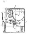
- Fig. 1 is a partially cut-away cross section showing the entire construction of the wet towel supplying apparatus that includes a pulling means and a cutting means.
- Cloth 3 such as non-woven fabric, which is wound in the form of a roll, is positioned in the rear portion of the interior of an upstanding housing 5.
- a control board 4 is disposed in the front surface of the housing 5.
- a wet towel storage chamber 6 is positioned in the lower front portion of the housing 5.
- the pulling means 7 and the cutting means 9 mounted in a casing 11 are positioned in front of the cloth 3. The cloth 3 is inserted into the pulling means 7 that is operated by a first motor 13, and is pulled toward the cutting means 9.
- the cutting means 9 using a known cutting method is operated by a second motor 15 and is positioned below the pulling means 7.
- a towel winding means 17 is operated by a third motor 16 and is connected to a nozzle of a water supplying means 21.
- An auxiliary water storage tank 23 is positioned in the lower portion of the housing 5 and includes a temperature regulating means and a pump, the temperature regulating means comprising a known electric heater or a known heat exchanger.
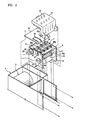
- Fig. 2 is an exploded perspective view showing the pulling means 7 and the cutting means 9 that are mounted in the casing 11.
- Fig. 3 is a vertical cross section showing the operation of the pulling means 7 and the cutting means 9.
- the pulling means 7 and the cutting means 9 are mounted in the casing 11.
- the casing 11 is fixed to the housing 5 by means of bolts, thereby allowing the casing 11 to be easily mounted and removed.
- the pulling means 7 includes a first shaft 25 and a second shaft 27 that are rotated by means of the first motor 13.
- the first shaft 25 is connected to the rotating shaft of the first motor 13 through gears.
- the second shaft 27 is mounted to the casing 11, with the second shaft 27 being parallel to the first shaft 25.
- the first shaft 25 and the second shaft 27 are operated together by means of pulleys 29a, 29b and bands 31, with the pulleys 29a, 29b being mounted along the first shaft 25 and the second shaft 27 and the bands 31 passing a pair of opposing pulleys 29a, 29b.
- the pulling means 7 further comprises a rake-shaped guide plate 33 and an L-shaped bent cover 35.
- the guide plate 33 is fixed to the upper portion of the housing 5 at its one side by means of bolts so as to be positioned over the pulling means 7.
- the cover 35 is fixed to the casing 11 with the fixing projections 35a of the cover 35 being inserted into the fixing holes 35b of the casing 11, so as to cover the upper portion and a front portion of the casing 11.
- a plurality of rollers 37 which are in contact with the upper surface of the cloth 36(refer to Fig. 3), are situated at corresponding spots at which the bands 31 are located.
- the rollers 37 are extruded downwards from the lower surface of the cover 35 by elastic means such as springs.
- the cloth 36 passes through the space between the upper surface of the guide plate 33 and the rollers 37.
- Guide slits 39 (refer to Fig. 3) are formed along the length of the guide plate 33 at positions that correspond to the positions of bands 31.
- the bands 31 are projected from the upper surface of the guide plate 33 through the guide slits 39 and are rotated.
- the rollers 37 are mounted so as to correspond to the bands 31, and so press against the upper surfaces of the bands 31.
- the rollers 37 are elastically mounted in the cover 35 so as to be elastically moved upwards and downwards, and so press against the bands 37 with a constant force. Therefore, the cloth 36 may be inserted into the space between each of the rollers 37 and each of the bands 31.
- the cutting means 9 comprises a fixed cutter 41 that is mounted under the front end of the pulling means 7 and a rotary cutter 43 that is rotated in response to a signal transmitted from a control means (not shown).
- the rotary cutter 43 which is inserted to a certain depth along the length of the rotating cutter shaft 44, is connected to the second motor 15 through gears.
- the rotary cutter 43 is mounted along the entire length of the cutter shaft so as to be projected uniformly. As shown in Fig. 3, the cloth 36 is cut when the cutters 41 and 43 are intersected.
- the pulling means 7 and the cutting means 9 are individually operated by different motors 13 and 15. Such a construction allows a user to regulate the length of a wet towel freely using a tachometer.
- the pulling means 7 comprises a rotating plate 45 and a first sensor 47 as a rotation sensing means, the rotating plate 45 being connected to a rotating shaft 25 and the first sensor 47 being connected to the rotating plate 45.
- the cutting means 9 has a cam plate 49 and a second sensor 51, the cam plate 49 being connected to the rotating cutter shaft 44.
- the control board 4 has a control part, such as a keypad or buttons, and a display.
- the control board 4 is used to regulate the length of the towel and set the temperature of the water.
- a control means (not shown) comprises the control board 4(refer to Fig. 3), the first sensor 47, the second sensor 51, a microprocessor and a temperature control unit.
- the first sensor 47 senses the length of the cloth that is pulled by the pulling means 7.
- the second sensor 51 senses the total number of the rotation of the rotary cutter of the cutting means.
- the microprocessor controls power supply to the first motor, the second motor and the pump of the water supplying means by processing the signals from the control board 4, the first sensor 47 and the second sensor 51.
- the temperature control unit controls the cooling means and the heating means of the water storage unit in response to the signal from the control board 4.
- the first sensor 47 of the pulling means 7 transmits a signal to the control means when 300mm of the cloth is pulled.
- the control means that received this signal operates the second motor 15. Since one rotation of the rotating cutter shaft 44 is sufficient for cutting the cloth, the second sensor 51 transmits a signal to the control means when the second sensor 51 senses one rotation of the rotating cutter shaft 44.
- the control means that received this signal stops the second motor 15. Additionally, the control means stops the first motor 13 of the pulling means 7 while the cutting means 9 cuts the cloth.
- control means may control the total number of supplied towels. That is, if the apparatus is operated while a user sets the desired number of towels to be three using the control board 4 (refer to Fig. 1), the control means may control the apparatus so as to supply three towels. To this end, the cutting means 9 may be provided with a counter.
- Fig. 4 is a partially cut-away cross section of a water tank showing the improvement in the filtering unit of the water supplying means.
- the water tank 53 has a filter unit that is connected to the main body of the water tank 53.
- the filter of the filter unit is easily removed while a cap 55 is opened.
- the water in the water tank is supplied to the auxiliary water storage tank 23(refer to Fig. 1) along the arrows of Fig. 4. This construction makes the replacement of the filter easy and the apparatus simple.
- the automatic wet towel supplying apparatus may be constructed in the form of a vending machine (not shown). Such a type of an apparatus may be used in an opened area.
- the towel winding means 17 is a characteristic of the present invention.
- Fig. 5 is a perspective view showing the towel winding means according to the present invention.
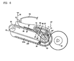
- Fig. 6 is a side view showing the operation of the towel winding means. Referring to Figs. 5 and 6, the towel winding means is described, hereinafter.
- a third shaft 61 and a fourth shaft 63 are rotatably mounted between both side plates 64 that form a frame, the third shaft 61 and the fourth shaft 63 being spaced apart from each other.
- a rubber belt 65 passes around the third shaft 61 and the fourth shaft 63 and serves as a movement transmitting means.
- the fourth shaft 63 is connected to a fourth motor 19(refer to Fig. 1) by means of gears and serves as a driving shaft, while the third shaft 61 serves as a driven shaft by means of the rubber belt 65.
- the rubber belt 65 serves as a conveyor belt that moves cut towels toward the fourth shaft 63.
- the rubber belt 65 may have a rugged surface so as to prevent the removal of the towel on its surface.
- the rubber belt 65 may have a known configuration for winding the towels effectively.
- a spread plate 67 is mounted between the side plates 64, the spread plate 67 being vertically spaced apart from the rubber belt 65.
- An auxiliary winding means 69 is provided in the rear of the spread plate 67.
- the auxiliary winding means 69 comprises a fifth shaft 73 and a sixth shaft 75 that are rotated together by means of one or more ring belts 71.
- the fifth shaft 73 and the fourth shaft 63 are rotated together by means of pulleys 77 and 79 and a movement transmitting belt 81.
- a rubber belt which is operated quietly and is resistant to humidity, may be employed and, more preferably, a timing belt may be employed so as to prevent unexpected removal.
- the ring belts 71 may be made of silicon and may be arranged to be spaced apart from each other. Consequently, although any one of the ring belts 71 is cut, it is not needed to change all the ring belts 71. However, since it may be difficult to keep uniform tension when such ring belts 71 are employed, one wide ring belt may be employed.
- a guide member 83 does not prevent only the lateral movement of the ring belts 71 but also prevents the towels from getting out of space between the ring belts 71. As shown, the guide member 83 is inserted into the grooves 85 that are vertically formed on the inner surfaces of the side plates 64.
- the sixth shaft 75 which is connected to the fifth shaft 73, is mounted to be able to be moved upwards for the increasable diameter of the towel is increased in the process of winding the towel.
- two curved slots 87 are formed in the side plates 64.
- a bracket 89 is positioned between the fifth shaft 73 and the sixth shaft 75 so as to keep a constant distance between the fifth shaft 73 and the sixth shaft 75.
- the rubber belt 65 may be provided with a plurality of discharge holes (not shown) of small diameters. According to this construction, residual water that is sprayed on the towels falls down through the discharge holes while the towels are moved.
- a nozzle 91 which is a part of the water supplying means 21, is positioned in front of the towel winding means 17.
- the nozzle 91 is provided with a plurality of injection holes with the injection holes facing downwards.
- Water is supplied to the nozzle 91 through a water supplying pipe 93.
- Nozzle can be provided in the form of pipe that is fixed at plates 64. According to this construction, water is uniformly sprayed on the towels that are moved by the rubber belt 65.
- a conveying roller 95 is mounted to the spread plate 67 so as to convey the towel 36' properly.
- the spread plate 67 includes a rubber plate 99 that has a plurality of tiny, sharp projections 97.
- the projections 97 are arranged over the one surface of the rubber plate 99 and, preferably have cone-shapes, respectively. Since the lengths of the projections 97 become shorter toward the rear of the apparatus, the gap between the spread plate 67 and the rubber belts 65 becomes wider, thereby moving the towels to the auxiliary winding means 69 while the towel is wound somewhat.
- the projections 97 spread the moved towels uniformly like a comb and remove residual water from the towels. The removed residual water may be eliminated through the discharge holes (not shown).
- a support plate 100 allows the wound towels, which pass the sixth shaft 75, to be moved to the wet towel storage chamber 6(refer to Fig. 1), with the wound towels being in contact with the rubber belt 65.
- the support plate 100 is spaced apart from the rubber belt 65 and is extended so as to surround the rear portion of the rubber belt 65 and the lower portion of the rubber belt 65.
- the support plate 100 has a plurality of projections 100a along its inner surface, which is in contact with the towels, so as to prevent the slip of the towels.
- the cut, wet towels 36, 36' and 36" are moved while laid on the upper surface of the rubber belt 65.
- the towels reach the fifth shaft 73.
- the wet towels pass the sixth shaft 75 while wound by means of the ring belts 71 that pass the fifth shaft 73 and the sixth shaft 75.
- the wet towels are rapidly wound by the oppositely rotated rubber belt 65 and the ring belts 71, thereby shortening the length of the apparatus and allowing the longer towels to be wound by the apparatus.
- the apparatus according to the present invention may supply various lengths of wet towels to a user.
- a towel is wound and supplied within 3-4 seconds per a sheet, and the maximum length of the towel that may be supplied by the apparatus ranges from 150mm to 500mm.
- the spread plate 67 is mounted using a spring 101, a washer 103 and a bolt 105 so as to be moved vertically, the bolt 105 being fixed to the side plate 64.
- This construction reduces the resistance of the apparatus, which is increased, accordingly as the diameter of the towel becomes larger.
- the roller 95 may be moved vertically together with the spread plate 67 and is rotated while in contact with the upper surface of the towel. As a consequence, the towel is conveyed while residual water is removed from the towel and the towel is spread uniformly.
- the present invention provides an automatic wet towel supplying apparatus that is capable of regulating the length of a wet towel in accordance with a user's request.
- the present invention provides an automatic wet towel supplying apparatus that is capable of winding a towel while the towel is spread uniformly.
- the present invention provides an automatic wet towel supplying apparatus that is capable of removing residual water from a towel using projections formed on the bottom surface of a spread plate.
- the present invention provides an automatic wet towel supplying apparatus that is capable of reducing the noise and the abrasion of the apparatus and being operated properly by employing sensors 47 and 51.
- the present invention provides an automatic wet towel supplying apparatus in which a pulling means and a cutting means are mounted in a casing 11 that is easily mounted easily removed, thereby making the maintenance and the cleaning of the apparatus easy.
Landscapes
- Health & Medical Sciences (AREA)
- Public Health (AREA)
- Body Washing Hand Wipes And Brushes (AREA)
- Confectionery (AREA)
- General Preparation And Processing Of Foods (AREA)
- Loading And Unloading Of Fuel Tanks Or Ships (AREA)
Claims (11)
- Distributeur automatique pour serviettes humidifiées, comportant :un logement (5) comprenant une section de retenue du tissu destinée à retenir, de manière rotative, le tissu (36) sous la forme d'un rouleau (3) de telle manière que le tissu est tiré, et une chambre de stockage des serviettes (6) destinée à stocker des serviettes coupées, humidifiées pour être distribuées ;un boítier (11) qui est assujetti sur une portion avant d'un intérieur du logement par le biais de boulons de telle manière à pouvoir être facilement retiré du logement;un moyen (7) destiné à tirer sur le tissu tout en comprimant le tissu, le moyen de tirage comprenant,
un premier moteur (13),
un premier arbre (25) qui est connecté au premier moteur par le biais d'engrenages,
un deuxième arbre (27) qui est activé en même temps que le premier arbre par le biais d'une courroie,
un capot (35) qui est situé au-dessus de la courroie tout en étant assujetti sur le logement et
un rouleau (37) qui est assujetti de manière rotative tout en étant projeté en provenance d'une surface inférieure du capot ;un moyen de coupe (9) qui comprend un deuxième moteur (15), une coupeuse rotative (43) mise en rotation par le deuxième moteur, et une coupeuse fixe (41) assujettie en une position dans laquelle la coupeuse fixe croise la coupeuse rotative, le moyen de tirage (7) et le moyen de coupe (9) étant montés dans le boítier (11) ;un moyen d'alimentation en eau (21) étant monté dans le logement, comprenant un réservoir de stockage d'eau (53), une pompe, une unité de filtration et une buse (91), et servant à pulvériser de l'eau sur les serviettes coupées ; etun moyen de commande qui comprend un tableau de commande (4) monté sur une surface extérieure du logement, un premier détecteur (47) destiné à détecter une longueur du tissu qui est tiré par le biais du moyen de tirage, un deuxième détecteur (51) destiné à détecter un nombre total de rotations de la coupeuse rotative du moyen de coupe, et un microprocesseur destiné à commander l'alimentation électrique du premier moteur, du deuxième moteur et de la pompe par le traitement des signaux provenant du tableau de commande, du premier détecteur et du deuxième détecteur. - Distributeur selon la revendication 1, dans lequel ladite courroie dudit moyen de tirage est une pluralité de courroies à anneaux qui passent au niveau du premier arbre et du deuxième arbre et qui sont espacées l'une par rapport à l'autre.
- Distributeur selon la revendication 1, dans lequel ledit rouleau est monté de manière élastique sur une partie inférieure du capot de telle manière à traiter diverses épaisseurs de tissu par le biais d'un mouvement de manière élastique et de manière verticale.
- Distributeur selon la revendication 1, dans lequel ledit premier détecteur et ledit deuxième détecteur sont des tachymètres, respectivement.
- Distributeur selon la revendication 1, dans lequel ledit tableau de commande dudit moyen de commande comprend des boutons de sélection destinés à régler une longueur de la serviette humidifiée et des boutons de sélection destinés à sélectionner le nombre de serviettes humidifiées.
- Distributeur selon la revendication 1, dans lequel ledit moyen d'alimentation en eau comprend par ailleurs un moyen de chauffage et de refroidissement destiné à régler une température de l'eau.
- Distributeur selon la revendication 1, comportant par ailleurs un moyen (17) destiné à enrouler la serviette humidifiée et à transporter la serviette enroulée jusqu'à la chambre de stockage des serviettes, ce moyen comprenant :un troisième moteur monté dans le logement,deux plaques latérales assujetties sur un cadre tout en étant espacées l'une par rapport à l'autre,un troisième arbre monté de manière rotative entre les portions avant des plaques latérales,un quatrième arbre connecté au troisième moteur par le biais d'engrenages et monté de manière rotative entre les portions arrière des plaques latérales,une courroie en caoutchouc passant au niveau du troisième arbre et du quatrième arbre et transportant les serviettes humidifiées vers l'arrière,un cinquième arbre monté de manière rotative entre les plaques latérales tout en étant espacé vers le haut par rapport à la courroie en caoutchouc et connecté au quatrième arbre par le biais d'une courroie,un sixième arbre monté de manière rotative entre les plaques latérales tout en étant espacé vers le haut par rapport à la courroie en caoutchouc et connecté au cinquième arbre par le biais de courroies à anneaux de telle manière à enrouler les serviettes, etune plaque de support (100) servant à permettre aux serviettes enroulées, qui passent au niveau du sixième arbre, d'être déplacées jusqu'à la chambre de stockage des serviettes humidifiées (6) alors que les serviettes enroulées sont en contact avec la courroie en caoutchouc, et étant prolongée de telle manière à entourer la portion arrière de la courroie en caoutchouc et la portion inférieure de la courroie en caoutchouc tout en étant espacée par rapport à la courroie en caoutchouc.
- Distributeur selon la revendication 7, dans lequel ledit sixième arbre est monté de manière rotative sur des fentes qui sont formées de manière courbe dans les plaques latérales, de telle manière à être déplacé vers le haut alors qu'il est connecté au cinquième arbre.
- Distributeur selon la revendication 7, comportant par ailleurs une plaque d'étalement, la plaque d'étalement étant montée entre les deux plaques latérales, étant positionnée devant le cinquième arbre et étant espacée de manière verticale par rapport à la courroie en caoutchouc.
- Distributeur selon la revendication 9, dans lequel ladite plaque d'étalement a une pluralité de projections minuscules, pointues et souples qui extraient toute eau résiduelle de la serviette et qui étalent la serviette de manière uniforme.
- Distributeur selon la revendication 9, dans lequel ladite plaque d'étalement comporte par ailleurs deux ou plusieurs rouleaux qui sont projetés vers le bas de telle manière à être mis en rotation tout en appuyant contre une surface supérieure de la serviette.
Applications Claiming Priority (4)
| Application Number | Priority Date | Filing Date | Title |
|---|---|---|---|
| KR10-1999-0035708A KR100428239B1 (ko) | 1999-08-26 | 1999-08-26 | 물수건 말이 장치 |
| KR9935708 | 1999-08-26 | ||
| KR1019990056272A KR100353522B1 (ko) | 1999-12-09 | 1999-12-09 | 물수건 제작기 |
| KR9956272 | 1999-12-09 |
Publications (2)
| Publication Number | Publication Date |
|---|---|
| EP1078593A1 EP1078593A1 (fr) | 2001-02-28 |
| EP1078593B1 true EP1078593B1 (fr) | 2005-01-26 |
Family
ID=26636074
Family Applications (1)
| Application Number | Title | Priority Date | Filing Date |
|---|---|---|---|
| EP00307244A Expired - Lifetime EP1078593B1 (fr) | 1999-08-26 | 2000-08-22 | Distributeur automatique pour serviettes humidifiées |
Country Status (8)
| Country | Link |
|---|---|
| US (1) | US6343491B1 (fr) |
| EP (1) | EP1078593B1 (fr) |
| JP (1) | JP3355554B2 (fr) |
| CN (1) | CN1286067A (fr) |
| AT (1) | ATE287658T1 (fr) |
| DE (1) | DE60017649D1 (fr) |
| TR (1) | TR200002490A2 (fr) |
| TW (1) | TW431879B (fr) |
Families Citing this family (48)
| Publication number | Priority date | Publication date | Assignee | Title |
|---|---|---|---|---|
| US6668843B2 (en) * | 2001-04-17 | 2003-12-30 | Yen Sun Technology Corp. | Method for manufacturing a wet towel and the apparatus thereof |
| JP3488231B1 (ja) * | 2002-10-16 | 2004-01-19 | クローバー有限会社 | おしぼり製造装置 |
| US7009519B2 (en) * | 2002-11-21 | 2006-03-07 | S.C. Johnson & Sons, Inc. | Product dispensing controlled by RFID tags |
| US7018473B2 (en) | 2003-04-10 | 2006-03-28 | Shadrach Iii William S | Towel dispensing and treatment system |
| JP2005095273A (ja) * | 2003-09-24 | 2005-04-14 | Fuji Denzai:Kk | 巻きおしぼり製造装置 |
| US6903307B1 (en) * | 2004-10-04 | 2005-06-07 | Prince Lionheart, Inc. | Hygienic wipes steamer |
| US20060289440A1 (en) * | 2004-10-04 | 2006-12-28 | Mcconnell Thomas E | Hygienic wipes steamer |
| US20070145617A1 (en) * | 2005-12-28 | 2007-06-28 | Kimberly-Clark Worldwide, Inc. | Processes for producing microencapsulated heat delivery vehicles |
| US20070149435A1 (en) * | 2005-12-28 | 2007-06-28 | Kimberly-Clark Worldwide, Inc. | Cleansing composition including microencapsulated delivery vehicles |
| US20070148459A1 (en) * | 2005-12-28 | 2007-06-28 | Kimberly-Clark Worldwide, Inc. | Microencapsulated delivery vehicles |
| US20070148448A1 (en) * | 2005-12-28 | 2007-06-28 | Kimberly-Clark Worldwide, Inc. | Microencapsulated delivery vehicles including cooling agents |
| US7442439B2 (en) * | 2005-12-28 | 2008-10-28 | Kimberly-Clark Worldwide, Inc. | Microencapsulated heat delivery vehicles |
| US7914891B2 (en) * | 2005-12-28 | 2011-03-29 | Kimberly-Clark Worldwide, Inc. | Wipes including microencapsulated delivery vehicles and phase change materials |
| US20070145619A1 (en) * | 2005-12-28 | 2007-06-28 | Kimberly-Clark Worldwide, Inc. | Processes for producing microencapsulated delivery vehicles |
| US20070148446A1 (en) * | 2005-12-28 | 2007-06-28 | Kimberly-Clark Worldwide, Inc. | Wipes including microencapsulated delivery vehicles and processes of producing the same |
| US20070202185A1 (en) * | 2005-12-28 | 2007-08-30 | Kimberly-Clark Worldwide, Inc. | Microencapsulated Delivery Vehicles Having Fugitive Layers |
| US7648046B2 (en) * | 2006-05-30 | 2010-01-19 | Kimberly-Clark Worldwide, Inc. | Dispensing system for dispensing warm wet wipes |
| US7497351B2 (en) | 2006-05-30 | 2009-03-03 | Kimberly-Clark Worldwide, Inc. | Wet wipe dispensing system |
| US7654412B2 (en) * | 2006-05-30 | 2010-02-02 | Kimberly-Clark Worldwide, Inc. | Wet wipe dispensing system for dispensing warm wet wipes |
| US7987810B1 (en) * | 2006-06-28 | 2011-08-02 | Karen Gordon | Articulating paper dispenser |
| US7517582B2 (en) | 2006-12-14 | 2009-04-14 | Kimberly-Clark Worldwide, Inc. | Supersaturated solutions using crystallization enthalpy to impart temperature change to wet wipes |
| US8192841B2 (en) * | 2006-12-14 | 2012-06-05 | Kimberly-Clark Worldwide, Inc. | Microencapsulated delivery vehicle having an aqueous core |
| US7597954B2 (en) | 2006-12-14 | 2009-10-06 | Kimberly-Clark Worldwide, Inc. | Supersaturated solutions using crystallization enthalpy to impact temperature change to wet wipes |
| US7856941B2 (en) | 2007-09-28 | 2010-12-28 | Steven D. Nelson | Wet wipe dispenser |
| US20090217870A1 (en) * | 2008-03-03 | 2009-09-03 | Georgia-Pacific Consumer Products Lp | Sheet Product and Flowable Product Dispenser System |
| US7924142B2 (en) * | 2008-06-30 | 2011-04-12 | Kimberly-Clark Worldwide, Inc. | Patterned self-warming wipe substrates |
| US20100286818A1 (en) * | 2009-05-08 | 2010-11-11 | Georgia-Pacific Consumer Products Lp | Sheet product dispenser with sensor for sheet separation |
| DE202009014152U1 (de) * | 2009-10-19 | 2011-03-03 | Dürr Optronik GmbH & Co. KG | Abrolleinrichtung für eine Materialbahn |
| US8783601B1 (en) | 2011-06-28 | 2014-07-22 | Gzim Shala | Wet wipe roll dispensing system |
| US9367983B2 (en) | 2012-09-18 | 2016-06-14 | June Tailor, Inc. | Systems and methods for dispensing soft goods |
| US8755933B2 (en) | 2012-09-18 | 2014-06-17 | June Tailor, Inc. | Systems and methods for dispensing soft goods |
| JP6171449B2 (ja) * | 2013-03-22 | 2017-08-02 | ツインバード工業株式会社 | 巻きおしぼり製造装置 |
| CN103505157B (zh) * | 2013-10-23 | 2015-10-28 | 湖州职业技术学院 | 一种家用地板清洁机 |
| US9532684B2 (en) | 2014-01-10 | 2017-01-03 | The Procter & Gamble Company | Wet/dry sheet dispenser and method of using |
| WO2015171273A1 (fr) * | 2014-05-06 | 2015-11-12 | June Tailor, Inc. | Systèmes et procédés de distribution d'articles souples |
| CN104016163B (zh) * | 2014-05-30 | 2016-04-13 | 上海洁之梦环保器材有限公司 | 商用柔巾机的装巾机构 |
| CN104016167B (zh) * | 2014-05-30 | 2016-03-16 | 上海洁之梦环保器材有限公司 | 商用柔巾机的复巾机构 |
| US9504363B2 (en) | 2014-06-20 | 2016-11-29 | The Procter & Gamble Company | Wet/dry sheet dispenser with dispensing cup |
| JP2016106700A (ja) * | 2014-12-03 | 2016-06-20 | プールス株式会社 | おしぼり製造装置 |
| JP2016174767A (ja) * | 2015-03-20 | 2016-10-06 | プールス株式会社 | おしぼり製造装置 |
| CN106264281B (zh) * | 2016-11-08 | 2019-04-30 | 雷庆诚 | 毛巾机 |
| CN107307789A (zh) * | 2017-03-07 | 2017-11-03 | 深圳润之和科技有限公司 | 一种多功能干湿两用纸巾出纸装置 |
| US10548435B2 (en) * | 2017-04-10 | 2020-02-04 | Robert Wise | Solution dispensing device |
| CN107468134A (zh) * | 2017-08-21 | 2017-12-15 | 广州凡而芳香日用品有限公司 | 一种自动化切纸机 |
| AU2020272849A1 (en) | 2019-04-11 | 2021-11-18 | Gojo Industries, Inc. | Dispensers for wet-on-demand substrates |
| CN112006588A (zh) * | 2020-08-31 | 2020-12-01 | 浙江康越电子有限公司 | 一种可控温的湿毛巾机 |
| CN112790651A (zh) * | 2021-01-27 | 2021-05-14 | 杭州诺亚方舟网络科技有限公司 | 一种自动出纸及货物售卖一体机 |
| CN112806887A (zh) * | 2021-02-08 | 2021-05-18 | 杭州商芯物联网科技有限公司 | 共享智能热湿巾机 |
Family Cites Families (21)
| Publication number | Priority date | Publication date | Assignee | Title |
|---|---|---|---|---|
| US3862616A (en) * | 1968-12-26 | 1975-01-28 | Robert C Brady | Dispensing unit for moistening material |
| US3672552A (en) * | 1970-02-03 | 1972-06-27 | Alwin Mfg Co Inc | Dispenser for web of perforated toweling sheets |
| US3707945A (en) * | 1970-06-18 | 1973-01-02 | P Boone | Means to selectively wet web material |
| DE2058667B1 (de) * | 1970-11-28 | 1972-05-25 | Weitmann & Konrad | Vorrichtung in Druckereimaschinen,insbesondere Offsetmaschinen,zum Aufbringen von Fluessigkeit auf bewegte Flaechen |
| NL7601031A (nl) * | 1976-02-02 | 1977-08-04 | Leonard Anthony Whight | Handdoekautomaat. |
| US4041900A (en) * | 1976-04-30 | 1977-08-16 | Charles James H | Pivoted guide means for selective immersion of web feed |
| US4655377A (en) * | 1985-07-31 | 1987-04-07 | Orangeo Jr Joseph | Apparatus for dispensing permanent wave processing paper |
| US4846412A (en) * | 1987-12-03 | 1989-07-11 | Wyant & Company Limited | Two roll sheet material dispenser |
| US4790490A (en) * | 1988-02-29 | 1988-12-13 | Shyamal Chakravorty | Self-locking, driver mechanism regulated tissue dispensing system with hands-free operation option |
| US4984530A (en) * | 1988-10-27 | 1991-01-15 | Core Medical Corporation | Hand wash towel dispensing system |
| US5048386A (en) * | 1989-10-27 | 1991-09-17 | Georgia-Pacific Corporation | Feed mechanism for flexible sheet material dispensers |
| DE4004124A1 (de) * | 1990-02-10 | 1991-08-14 | Feldmuehle Gmbh Scott | Vorrichtung zum ausgeben von bahnabschnitten von einer abgaberolle |
| US5078033A (en) * | 1990-11-13 | 1992-01-07 | Georgia-Pacific Corporation | Flexible sheet material dispenser |
| FR2671711B1 (fr) * | 1991-01-18 | 1993-03-26 | Elis Gie | Appareil distributeur de tissu d'essuie-mains. |
| DE69121729T2 (de) * | 1991-05-07 | 1997-01-30 | Remy Saleur | Vorrichtung zum befeuchten von papier und abgabevorrichtung von befeuchtetem hygienepapier |
| US5410930A (en) * | 1991-08-05 | 1995-05-02 | Georgia Pacific Corporation | Low operating force stop mechanism and dispensing method for rolled web dispensers |
| US5672206A (en) * | 1995-10-11 | 1997-09-30 | Gorman; Tom | Moistening dispenser for a roll of paper sheets |
| JP3213837B2 (ja) * | 1996-12-28 | 2001-10-02 | 滋胤 具 | 水タオル自動供給装置 |
| US5803397A (en) * | 1997-01-23 | 1998-09-08 | Chang; Liang-Min | Wet tissue rolling-up device |
| US6224010B1 (en) * | 1998-01-22 | 2001-05-01 | Perrin Manufacturing Company | Apparatus and method for dispensing paper toweling from a roll of paper toweling |
| JP2000070171A (ja) * | 1998-08-26 | 2000-03-07 | Trp:Kk | 消毒用ウエットワイパーおよびその供給装置 |
-
2000
- 2000-03-06 TW TW089104124A patent/TW431879B/zh not_active IP Right Cessation
- 2000-03-09 JP JP2000065329A patent/JP3355554B2/ja not_active Expired - Fee Related
- 2000-03-15 US US09/525,836 patent/US6343491B1/en not_active Expired - Fee Related
- 2000-03-30 CN CN00105350.7A patent/CN1286067A/zh active Pending
- 2000-08-22 AT AT00307244T patent/ATE287658T1/de not_active IP Right Cessation
- 2000-08-22 DE DE60017649T patent/DE60017649D1/de not_active Expired - Lifetime
- 2000-08-22 EP EP00307244A patent/EP1078593B1/fr not_active Expired - Lifetime
- 2000-08-25 TR TR2000/02490A patent/TR200002490A2/xx unknown
Also Published As
| Publication number | Publication date |
|---|---|
| DE60017649D1 (de) | 2005-03-03 |
| TW431879B (en) | 2001-05-01 |
| US6343491B1 (en) | 2002-02-05 |
| JP3355554B2 (ja) | 2002-12-09 |
| TR200002490A3 (tr) | 2001-07-23 |
| JP2001070194A (ja) | 2001-03-21 |
| CN1286067A (zh) | 2001-03-07 |
| EP1078593A1 (fr) | 2001-02-28 |
| TR200002490A2 (tr) | 2001-07-23 |
| ATE287658T1 (de) | 2005-02-15 |
Similar Documents
| Publication | Publication Date | Title |
|---|---|---|
| US6343491B1 (en) | Automatic wet towel supplying apparatus | |
| US5829278A (en) | Automatic wet towel supplying apparatus | |
| US6128826A (en) | Combination drying unit | |
| EP1681972B1 (fr) | Machine de presentation et de lavage de serviette et procede de fonctionnement associe | |
| CN100457009C (zh) | 卷巾制造装置 | |
| KR200180460Y1 (ko) | 물수건 제작기 | |
| KR100256780B1 (ko) | 물수건 제조기 | |
| JP3081592B2 (ja) | 巻おしぼり製造装置 | |
| JPH0399619A (ja) | 巻きおしぼり製造装置の運転方法 | |
| JPH0453532B2 (fr) | ||
| JP2009066138A (ja) | 巻きおしぼり製造装置 | |
| KR100428937B1 (ko) | 물수건 마는 장치 및 이를 이용하는 물수건 제조 장치 | |
| KR100436891B1 (ko) | 건수건 제조장치 | |
| JP2009066139A (ja) | 巻きおしぼり製造装置 | |
| JP2000139757A (ja) | 巻おしぼり製造装置 | |
| JP3694387B2 (ja) | 乗客コンベアの移動手摺清掃装置 | |
| JP3081580B2 (ja) | 巻おしぼり製造装置 | |
| JP3234446U (ja) | ウェットタオル自動製造装置 | |
| HK1033891A (zh) | 含水毛巾自动供给装置 | |
| KR910005284Y1 (ko) | 면봉 제조장치 | |
| JPH0517991Y2 (fr) | ||
| KR100609099B1 (ko) | 물수건 공급장치 및 그를 위한 벨트 | |
| US20020148083A1 (en) | Arrangement for brushing a fabric web | |
| JP3302662B2 (ja) | 巻きおしぼり製造装置 | |
| JP3302675B2 (ja) | 巻きおしぼり製造装置 |
Legal Events
| Date | Code | Title | Description |
|---|---|---|---|
| PUAI | Public reference made under article 153(3) epc to a published international application that has entered the european phase |
Free format text: ORIGINAL CODE: 0009012 |
|
| AK | Designated contracting states |
Kind code of ref document: A1 Designated state(s): AT BE CH CY DE DK ES FI FR GB GR IE IT LI LU MC NL PT SE |
|
| AX | Request for extension of the european patent |
Free format text: AL;LT;LV;MK;RO;SI |
|
| 17P | Request for examination filed |
Effective date: 20010426 |
|
| AKX | Designation fees paid |
Free format text: AT BE CH CY DE DK ES FI FR GB GR IE IT LI LU MC NL PT SE |
|
| GRAP | Despatch of communication of intention to grant a patent |
Free format text: ORIGINAL CODE: EPIDOSNIGR1 |
|
| GRAS | Grant fee paid |
Free format text: ORIGINAL CODE: EPIDOSNIGR3 |
|
| GRAA | (expected) grant |
Free format text: ORIGINAL CODE: 0009210 |
|
| AK | Designated contracting states |
Kind code of ref document: B1 Designated state(s): AT BE CH CY DE DK ES FI FR GB GR IE IT LI LU MC NL PT SE |
|
| PG25 | Lapsed in a contracting state [announced via postgrant information from national office to epo] |
Ref country code: IT Free format text: LAPSE BECAUSE OF FAILURE TO SUBMIT A TRANSLATION OF THE DESCRIPTION OR TO PAY THE FEE WITHIN THE PRESCRIBED TIME-LIMIT;WARNING: LAPSES OF ITALIAN PATENTS WITH EFFECTIVE DATE BEFORE 2007 MAY HAVE OCCURRED AT ANY TIME BEFORE 2007. THE CORRECT EFFECTIVE DATE MAY BE DIFFERENT FROM THE ONE RECORDED. Effective date: 20050126 Ref country code: FR Free format text: LAPSE BECAUSE OF FAILURE TO SUBMIT A TRANSLATION OF THE DESCRIPTION OR TO PAY THE FEE WITHIN THE PRESCRIBED TIME-LIMIT Effective date: 20050126 Ref country code: AT Free format text: LAPSE BECAUSE OF FAILURE TO SUBMIT A TRANSLATION OF THE DESCRIPTION OR TO PAY THE FEE WITHIN THE PRESCRIBED TIME-LIMIT Effective date: 20050126 Ref country code: FI Free format text: LAPSE BECAUSE OF FAILURE TO SUBMIT A TRANSLATION OF THE DESCRIPTION OR TO PAY THE FEE WITHIN THE PRESCRIBED TIME-LIMIT Effective date: 20050126 Ref country code: BE Free format text: LAPSE BECAUSE OF FAILURE TO SUBMIT A TRANSLATION OF THE DESCRIPTION OR TO PAY THE FEE WITHIN THE PRESCRIBED TIME-LIMIT Effective date: 20050126 Ref country code: CH Free format text: LAPSE BECAUSE OF FAILURE TO SUBMIT A TRANSLATION OF THE DESCRIPTION OR TO PAY THE FEE WITHIN THE PRESCRIBED TIME-LIMIT Effective date: 20050126 Ref country code: NL Free format text: LAPSE BECAUSE OF FAILURE TO SUBMIT A TRANSLATION OF THE DESCRIPTION OR TO PAY THE FEE WITHIN THE PRESCRIBED TIME-LIMIT Effective date: 20050126 Ref country code: LI Free format text: LAPSE BECAUSE OF FAILURE TO SUBMIT A TRANSLATION OF THE DESCRIPTION OR TO PAY THE FEE WITHIN THE PRESCRIBED TIME-LIMIT Effective date: 20050126 |
|
| REG | Reference to a national code |
Ref country code: GB Ref legal event code: FG4D |
|
| REG | Reference to a national code |
Ref country code: CH Ref legal event code: EP |
|
| REG | Reference to a national code |
Ref country code: IE Ref legal event code: FG4D |
|
| REF | Corresponds to: |
Ref document number: 60017649 Country of ref document: DE Date of ref document: 20050303 Kind code of ref document: P |
|
| PG25 | Lapsed in a contracting state [announced via postgrant information from national office to epo] |
Ref country code: GR Free format text: LAPSE BECAUSE OF FAILURE TO SUBMIT A TRANSLATION OF THE DESCRIPTION OR TO PAY THE FEE WITHIN THE PRESCRIBED TIME-LIMIT Effective date: 20050426 Ref country code: DK Free format text: LAPSE BECAUSE OF FAILURE TO SUBMIT A TRANSLATION OF THE DESCRIPTION OR TO PAY THE FEE WITHIN THE PRESCRIBED TIME-LIMIT Effective date: 20050426 Ref country code: SE Free format text: LAPSE BECAUSE OF FAILURE TO SUBMIT A TRANSLATION OF THE DESCRIPTION OR TO PAY THE FEE WITHIN THE PRESCRIBED TIME-LIMIT Effective date: 20050426 |
|
| PG25 | Lapsed in a contracting state [announced via postgrant information from national office to epo] |
Ref country code: DE Free format text: LAPSE BECAUSE OF FAILURE TO SUBMIT A TRANSLATION OF THE DESCRIPTION OR TO PAY THE FEE WITHIN THE PRESCRIBED TIME-LIMIT Effective date: 20050427 |
|
| PG25 | Lapsed in a contracting state [announced via postgrant information from national office to epo] |
Ref country code: ES Free format text: LAPSE BECAUSE OF FAILURE TO SUBMIT A TRANSLATION OF THE DESCRIPTION OR TO PAY THE FEE WITHIN THE PRESCRIBED TIME-LIMIT Effective date: 20050507 |
|
| NLV1 | Nl: lapsed or annulled due to failure to fulfill the requirements of art. 29p and 29m of the patents act | ||
| REG | Reference to a national code |
Ref country code: CH Ref legal event code: PL |
|
| PG25 | Lapsed in a contracting state [announced via postgrant information from national office to epo] |
Ref country code: IE Free format text: LAPSE BECAUSE OF NON-PAYMENT OF DUE FEES Effective date: 20050822 Ref country code: CY Free format text: LAPSE BECAUSE OF FAILURE TO SUBMIT A TRANSLATION OF THE DESCRIPTION OR TO PAY THE FEE WITHIN THE PRESCRIBED TIME-LIMIT Effective date: 20050822 Ref country code: LU Free format text: LAPSE BECAUSE OF NON-PAYMENT OF DUE FEES Effective date: 20050822 |
|
| PGFP | Annual fee paid to national office [announced via postgrant information from national office to epo] |
Ref country code: GB Payment date: 20050824 Year of fee payment: 6 |
|
| PG25 | Lapsed in a contracting state [announced via postgrant information from national office to epo] |
Ref country code: MC Free format text: LAPSE BECAUSE OF NON-PAYMENT OF DUE FEES Effective date: 20050831 |
|
| PLBE | No opposition filed within time limit |
Free format text: ORIGINAL CODE: 0009261 |
|
| STAA | Information on the status of an ep patent application or granted ep patent |
Free format text: STATUS: NO OPPOSITION FILED WITHIN TIME LIMIT |
|
| 26N | No opposition filed |
Effective date: 20051027 |
|
| EN | Fr: translation not filed | ||
| REG | Reference to a national code |
Ref country code: IE Ref legal event code: MM4A |
|
| GBPC | Gb: european patent ceased through non-payment of renewal fee |
Effective date: 20060822 |
|
| PG25 | Lapsed in a contracting state [announced via postgrant information from national office to epo] |
Ref country code: GB Free format text: LAPSE BECAUSE OF NON-PAYMENT OF DUE FEES Effective date: 20060822 |
|
| PG25 | Lapsed in a contracting state [announced via postgrant information from national office to epo] |
Ref country code: PT Free format text: LAPSE BECAUSE OF NON-PAYMENT OF DUE FEES Effective date: 20050626 |