EP1079059B1 - Elément de support - Google Patents
Elément de support Download PDFInfo
- Publication number
- EP1079059B1 EP1079059B1 EP00117570A EP00117570A EP1079059B1 EP 1079059 B1 EP1079059 B1 EP 1079059B1 EP 00117570 A EP00117570 A EP 00117570A EP 00117570 A EP00117570 A EP 00117570A EP 1079059 B1 EP1079059 B1 EP 1079059B1
- Authority
- EP
- European Patent Office
- Prior art keywords
- constrictions
- bearing
- bearing element
- strip
- openings
- Prior art date
- Legal status (The legal status is an assumption and is not a legal conclusion. Google has not performed a legal analysis and makes no representation as to the accuracy of the status listed.)
- Expired - Lifetime
Links
- 239000002184 metal Substances 0.000 claims description 5
- -1 polyethylene Polymers 0.000 claims description 5
- 229920006324 polyoxymethylene Polymers 0.000 claims description 3
- 229930182556 Polyacetal Natural products 0.000 claims description 2
- 239000004698 Polyethylene Substances 0.000 claims description 2
- 239000000463 material Substances 0.000 claims description 2
- 229920000573 polyethylene Polymers 0.000 claims description 2
- 229920001343 polytetrafluoroethylene Polymers 0.000 claims description 2
- 239000004810 polytetrafluoroethylene Substances 0.000 claims description 2
- 229930040373 Paraformaldehyde Natural products 0.000 claims 1
- 229920000642 polymer Polymers 0.000 claims 1
- 238000005096 rolling process Methods 0.000 description 7
- 230000005540 biological transmission Effects 0.000 description 3
- 230000003716 rejuvenation Effects 0.000 description 3
- 238000005452 bending Methods 0.000 description 2
- 238000004519 manufacturing process Methods 0.000 description 2
- 210000001331 nose Anatomy 0.000 description 2
- 239000004033 plastic Substances 0.000 description 2
- 229920003023 plastic Polymers 0.000 description 2
- 150000001875 compounds Chemical class 0.000 description 1
- 238000010276 construction Methods 0.000 description 1
- 238000005516 engineering process Methods 0.000 description 1
- 229920002457 flexible plastic Polymers 0.000 description 1
- 235000015095 lager Nutrition 0.000 description 1
- 238000002360 preparation method Methods 0.000 description 1
- 238000004080 punching Methods 0.000 description 1
- 238000003860 storage Methods 0.000 description 1
Images



Classifications
-
- E—FIXED CONSTRUCTIONS
- E06—DOORS, WINDOWS, SHUTTERS, OR ROLLER BLINDS IN GENERAL; LADDERS
- E06B—FIXED OR MOVABLE CLOSURES FOR OPENINGS IN BUILDINGS, VEHICLES, FENCES OR LIKE ENCLOSURES IN GENERAL, e.g. DOORS, WINDOWS, BLINDS, GATES
- E06B3/00—Window sashes, door leaves, or like elements for closing wall or like openings; Layout of fixed or moving closures, e.g. windows in wall or like openings; Features of rigidly-mounted outer frames relating to the mounting of wing frames
- E06B3/54—Fixing of glass panes or like plates
- E06B3/58—Fixing of glass panes or like plates by means of borders, cleats, or the like
- E06B3/62—Fixing of glass panes or like plates by means of borders, cleats, or the like of rubber-like elastic cleats
-
- E—FIXED CONSTRUCTIONS
- E06—DOORS, WINDOWS, SHUTTERS, OR ROLLER BLINDS IN GENERAL; LADDERS
- E06B—FIXED OR MOVABLE CLOSURES FOR OPENINGS IN BUILDINGS, VEHICLES, FENCES OR LIKE ENCLOSURES IN GENERAL, e.g. DOORS, WINDOWS, BLINDS, GATES
- E06B3/00—Window sashes, door leaves, or like elements for closing wall or like openings; Layout of fixed or moving closures, e.g. windows in wall or like openings; Features of rigidly-mounted outer frames relating to the mounting of wing frames
- E06B3/54—Fixing of glass panes or like plates
- E06B3/5436—Fixing of glass panes or like plates involving holes or indentations in the pane
-
- F—MECHANICAL ENGINEERING; LIGHTING; HEATING; WEAPONS; BLASTING
- F16—ENGINEERING ELEMENTS AND UNITS; GENERAL MEASURES FOR PRODUCING AND MAINTAINING EFFECTIVE FUNCTIONING OF MACHINES OR INSTALLATIONS; THERMAL INSULATION IN GENERAL
- F16C—SHAFTS; FLEXIBLE SHAFTS; ELEMENTS OR CRANKSHAFT MECHANISMS; ROTARY BODIES OTHER THAN GEARING ELEMENTS; BEARINGS
- F16C33/00—Parts of bearings; Special methods for making bearings or parts thereof
- F16C33/30—Parts of ball or roller bearings
- F16C33/46—Cages for rollers or needles
- F16C33/50—Cages for rollers or needles formed of interconnected members, e.g. chains
-
- E—FIXED CONSTRUCTIONS
- E06—DOORS, WINDOWS, SHUTTERS, OR ROLLER BLINDS IN GENERAL; LADDERS
- E06B—FIXED OR MOVABLE CLOSURES FOR OPENINGS IN BUILDINGS, VEHICLES, FENCES OR LIKE ENCLOSURES IN GENERAL, e.g. DOORS, WINDOWS, BLINDS, GATES
- E06B3/00—Window sashes, door leaves, or like elements for closing wall or like openings; Layout of fixed or moving closures, e.g. windows in wall or like openings; Features of rigidly-mounted outer frames relating to the mounting of wing frames
- E06B3/54—Fixing of glass panes or like plates
- E06B3/58—Fixing of glass panes or like plates by means of borders, cleats, or the like
- E06B3/62—Fixing of glass panes or like plates by means of borders, cleats, or the like of rubber-like elastic cleats
- E06B2003/625—Specific form characteristics
- E06B2003/6264—Specific form characteristics hollow
-
- E—FIXED CONSTRUCTIONS
- E06—DOORS, WINDOWS, SHUTTERS, OR ROLLER BLINDS IN GENERAL; LADDERS
- E06B—FIXED OR MOVABLE CLOSURES FOR OPENINGS IN BUILDINGS, VEHICLES, FENCES OR LIKE ENCLOSURES IN GENERAL, e.g. DOORS, WINDOWS, BLINDS, GATES
- E06B3/00—Window sashes, door leaves, or like elements for closing wall or like openings; Layout of fixed or moving closures, e.g. windows in wall or like openings; Features of rigidly-mounted outer frames relating to the mounting of wing frames
- E06B3/54—Fixing of glass panes or like plates
- E06B3/58—Fixing of glass panes or like plates by means of borders, cleats, or the like
- E06B3/62—Fixing of glass panes or like plates by means of borders, cleats, or the like of rubber-like elastic cleats
- E06B2003/627—Fixing of glass panes or like plates by means of borders, cleats, or the like of rubber-like elastic cleats with specific characteristics concerning the material
- E06B2003/6276—Fixing of glass panes or like plates by means of borders, cleats, or the like of rubber-like elastic cleats with specific characteristics concerning the material with parts of differing nature, e.g. hardness
-
- E—FIXED CONSTRUCTIONS
- E06—DOORS, WINDOWS, SHUTTERS, OR ROLLER BLINDS IN GENERAL; LADDERS
- E06B—FIXED OR MOVABLE CLOSURES FOR OPENINGS IN BUILDINGS, VEHICLES, FENCES OR LIKE ENCLOSURES IN GENERAL, e.g. DOORS, WINDOWS, BLINDS, GATES
- E06B3/00—Window sashes, door leaves, or like elements for closing wall or like openings; Layout of fixed or moving closures, e.g. windows in wall or like openings; Features of rigidly-mounted outer frames relating to the mounting of wing frames
- E06B3/54—Fixing of glass panes or like plates
- E06B3/58—Fixing of glass panes or like plates by means of borders, cleats, or the like
- E06B3/62—Fixing of glass panes or like plates by means of borders, cleats, or the like of rubber-like elastic cleats
- E06B2003/627—Fixing of glass panes or like plates by means of borders, cleats, or the like of rubber-like elastic cleats with specific characteristics concerning the material
- E06B2003/6282—Fixing of glass panes or like plates by means of borders, cleats, or the like of rubber-like elastic cleats with specific characteristics concerning the material of cellular nature
Definitions
- the invention includes a bearing element and a bearing, in particular for a TV.
- the known bearing element is a device-specific Special part.
- the production of such special parts is expensive.
- the receiving element is as formed flexible band.
- band here are both a band-shaped and rod-like elements understood.-
- Such a bearing element is simple and inexpensive produced. It can be kept in stock by the meter. By the flexible Training, the tape can be adapted to the respective storage form.
- the Bearing element is therefore universally applicable.
- the provision of the tapers allows the tape in two To bend perpendicular to each other planes and from it if necessary, make a ring.
- the bearing element in a, preferably annular channel-like trained, guided tour. This increases the reliability.
- the two ends are not necessarily tight together be connected.
- a second ring bent around the first tapers Bearing element can be performed in a circumferential axis around the guide.
- a pipe socket is expediently with its inner wall to the Rolling elements of the first bearing elements and is axially on the rolling elements supported the second bearing element.
- On the opposite side can he be attached to a support plate.
- the carrier plate is used for attachment or for receiving the object to be rotated
- an easy-to-implement rotating device can at the the base plate facing the underside of the carrier plate a Electric motor and a transmission having drive for turning the Be included support plate.
- the rotational movement of the engine is expediently by means of a V-belt from the gearbox to the axle transfer.
- a radial groove can be provided on the axle.
- the proposed bearings or the rotating device is particularly compact and easy to set up. By providing a V-belt this fulfills Turning also the function of a slip clutch.
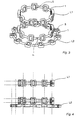
- a made of a flexible plastic - here partially shown - Band 1 has a first width b1 and in Area of a breakthrough 2 a second width b2. In the first width b1 are first tapered 3 provided. The band 1 also has in the area between breakthroughs 2, a first height h1. Around Breakthroughs 2, the height of the band 1 with a height h2 is slightly larger educated. In the first height h1, a second taper 4 is formed, which is perpendicular to the first taper 3.
- the band 1 is here - as shown in Figure 4 - formed like a chain.
- the the Breakthroughs 2 surrounding sections are round in cross-section formed intermediate sections connected to each other.
- the first width b1 and the first height h1 are the same size here.
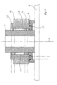
- FIGS. 5-8 show a bearing for a television set. How best 7 is apparent on a base plate 6 is a perpendicular thereof extending axis 7 attached. Connected to the axis 7 is a Pulley 8. Within a formed by the pulley 8 Guide 9 is a first bearing element L1 bent into a ring added. The first bearing element L1 serves as a thrust bearing. It is formed by bending the band 1 around the first tapers 3.
- Second bearing elements L2 are going through a pipe section 11 held axially spaced from each other.
- the second Bearing elements L2 are by bending the band 1 to the second Rejuvenations 4 made.
- On the pipe socket 10 is a support plate 12th attached.
- L1 For the preparation of the bearing elements L1, L2 is a section given Length separated from the band 1 shown in Fig.1 and Fig.2.
- the section Depending on the intended use, it will be either the first 3 or the second Tapered 4 bent into a ring.
- the ends of the section will be connected with each other. This can be done with a suitable punching device hook-like recesses may be provided at the ends. Such hook-like recesses are in Figure 3 by the reference H indicated.
- hook connection of the two ends are also other compounds, e.g. a plug connection or a Connection by means of a tube or a sleeve conceivable.
Landscapes
- Engineering & Computer Science (AREA)
- Civil Engineering (AREA)
- Structural Engineering (AREA)
- General Engineering & Computer Science (AREA)
- Mechanical Engineering (AREA)
- Rolling Contact Bearings (AREA)
- Support Of The Bearing (AREA)
Claims (9)
- Élément de support dans lequel un élément de réception présentant une première hauteur (h1) est muni de traversées (2) dans lesquelles sont reçus en rotation des éléments roulants (5) présentant un diamètre (D), le diamètre (D) étant supérieur à la première hauteur (h1) et l'élément de réception étant réalisé sous forme de bande flexible (1), caractérisé en ce que la bande (1) présente dans une première largeur (b1) de premiers rétrécissements (3) et dans la première hauteur (h1) de seconds rétrécissements (4), les premiers rétrécissements (3) étant décalés par rapport aux seconds rétrécissements (4) en direction longitudinale de la bande (1), et les premiers rétrécissements (3) et les seconds rétrécissements (4) étant agencés chacun entre deux traversées (2).
- Élément de support selon la revendication 1, dans lequel les éléments roulants (5) sont retenus de façon imperdable dans les traversées (2).
- Élément de support selon l'une des revendications précédentes, dans lequel les premiers (3) et/ou les seconds rétrécissements (4) sont agencés chacun entre deux traversées (2) et/ou les éléments roulants (5) fabriqués de préférence en métal sont réalisés sous forme de bille, de cylindre ou de cône et/ou la bande (1) présente dans la zone des traversées (2) une seconde largeur (b2) qui est supérieure à la première largeur (b1).
- Élément de support selon l'une des revendications précédentes, dans lequel la bande (1) est réalisée en métal ou en matière plastique, de préférence en un matériau de polyéthylène, tel que polyacétalpolyoxyméthylène ou polytétrafluoroéthylène.
- Élément de support selon l'une des revendications précédentes, dans lequel les deux extrémités de la bande (1) présentent une forme correspondante afin de les relier, de sorte que la bande (1) est susceptible de se fermer en une bague et/ou les deux extrémités sont réalisées de manière à permettre une liaison à enfichage, à coincement ou à enclenchement.
- Support, en particulier pour un appareil téléviseur, comportant un élément de support (L1, L2) selon l'une des revendications précédentes,
- Support selon la revendication 6, dans lequel l'élément de support est guidé dans un guidage (9) réalisé de préférence en forme de canal annulaire, et/ou deux premiers éléments de support (L1) recourbés autour des seconds rétrécissements (4) pour former une bague et maintenus écartés l'un de l'autre par un tronçon tubulaire (11) entourent un axe (7) qui s'étend à partir d'une plaque de base (6).
- Support selon l'une des revendications 6 et 7, dans lequel un second élément de support (L2) recourbé autour des premiers rétrécissements (3) pour former une bague est guidé dams un guidage (9) s'étendant autour de l'axe (7), et/ou le manchon tubulaire (10) prend appui par sa paroi intérieure contre les éléments roulants (5) des premiers éléments de support (L1) et est appuyé axialement sur les éléments roulants (5) du second élément de support (L2).
- Support selon l'une des revendications 6 à 8, dans lequel le manchon tubulaire (10) est fixé sur une plaque porteuse (12) et/ou un entraínement (A) destiné à faire tourner la plaque porteuse (12) et comprenant un moteur électrique (13) et un mécanisme de transmission (14) est reçu sur le côté inférieur de la plaque porteuse (12) tourné vers la plaque de base (6), et/ou le mouvement de rotation du moteur électrique (13) est transmis au moyen d'une courroie trapézoïdale depuis le mécanisme de transmission (14) à l'axe (7).
Applications Claiming Priority (2)
| Application Number | Priority Date | Filing Date | Title |
|---|---|---|---|
| DE19939920A DE19939920A1 (de) | 1999-08-23 | 1999-08-23 | Lagerelement |
| DE19939920 | 1999-08-23 |
Publications (3)
| Publication Number | Publication Date |
|---|---|
| EP1079059A2 EP1079059A2 (fr) | 2001-02-28 |
| EP1079059A3 EP1079059A3 (fr) | 2001-09-19 |
| EP1079059B1 true EP1079059B1 (fr) | 2005-07-06 |
Family
ID=7919309
Family Applications (1)
| Application Number | Title | Priority Date | Filing Date |
|---|---|---|---|
| EP00117570A Expired - Lifetime EP1079059B1 (fr) | 1999-08-23 | 2000-08-16 | Elément de support |
Country Status (2)
| Country | Link |
|---|---|
| EP (1) | EP1079059B1 (fr) |
| DE (2) | DE19939920A1 (fr) |
Families Citing this family (1)
| Publication number | Priority date | Publication date | Assignee | Title |
|---|---|---|---|---|
| DE102015209270A1 (de) * | 2015-05-21 | 2016-07-07 | Schaeffler Technologies AG & Co. KG | Massiver Wälzlagerkäfig für ein Axialwälzlager |
Family Cites Families (14)
| Publication number | Priority date | Publication date | Assignee | Title |
|---|---|---|---|---|
| US2566421A (en) * | 1948-11-23 | 1951-09-04 | Donald H Lapointe | Antifriction bearing-retaining strip |
| DE1973567U (de) * | 1967-07-12 | 1967-11-30 | Braun Ag | Drehgestell. |
| DE6932518U (de) * | 1969-08-13 | 1970-02-12 | Luedenscheid Spritzguss Werk | Waelzlagerkaefig, insbesondere in streifenform |
| DE3041860A1 (de) * | 1980-11-06 | 1982-06-03 | Industriewerk Schaeffler Ohg, 8522 Herzogenaurach | Kunststoffkaefig fuer waelzlager |
| DE3526627A1 (de) * | 1985-07-25 | 1987-02-05 | Skf Gmbh | Gliederkaefig fuer waelzlager |
| DE3635261A1 (de) * | 1986-01-17 | 1987-07-30 | Kabus Horst Maschf | Aus einem werkstoff spritzbarer kaefig fuer waelzlager |
| DE3722651A1 (de) * | 1987-07-09 | 1989-01-19 | Kugelfischer G Schaefer & Co | Waelzlagerkaefig |
| GB2260167B (en) * | 1989-12-11 | 1993-09-08 | Titus Tool Co Ltd | Turntable |
| JP2612518B2 (ja) * | 1991-08-22 | 1997-05-21 | テイエチケー 株式会社 | ボールチェイン及び直線運動案内装置 |
| US5346317A (en) * | 1993-08-09 | 1994-09-13 | Itt Corporation | Horizontal bearing arrangement with controlled drag |
| JPH07203335A (ja) * | 1993-12-28 | 1995-08-04 | Mitsubishi Electric Corp | 回転装置 |
| DE4400979C2 (de) | 1994-01-14 | 1997-07-24 | Gartner & Co J | Halterung zur Lagerung einer Platte |
| DE4445724C2 (de) | 1994-12-21 | 1997-08-07 | Gartner & Co J | Befestigungsanordnung von Platten |
| DE19519527C2 (de) | 1995-05-27 | 1999-11-18 | Seele Gmbh | Halterung für Platten |
-
1999
- 1999-08-23 DE DE19939920A patent/DE19939920A1/de not_active Withdrawn
-
2000
- 2000-08-16 DE DE50010654T patent/DE50010654D1/de not_active Expired - Lifetime
- 2000-08-16 EP EP00117570A patent/EP1079059B1/fr not_active Expired - Lifetime
Also Published As
| Publication number | Publication date |
|---|---|
| EP1079059A2 (fr) | 2001-02-28 |
| DE19939920A1 (de) | 2001-03-01 |
| EP1079059A3 (fr) | 2001-09-19 |
| DE50010654D1 (de) | 2005-08-11 |
Similar Documents
| Publication | Publication Date | Title |
|---|---|---|
| DE2936215C2 (fr) | ||
| WO1986004660A1 (fr) | Tuyau flexible avec ondes annulaires paralleles les unes aux autres et support axial | |
| DE102008016572A1 (de) | Verbindungselement | |
| EP1361373A1 (fr) | Roulement à contact oblique à double rangées de billes | |
| DE2217309C3 (de) | Vorrichtung zur Übertragung einer Drehbewegung | |
| DE4241915B4 (de) | Kugelumlaufschraubenvorrichtung | |
| EP2932119B1 (fr) | Palier à roulement | |
| EP2158412B1 (fr) | Systeme de palier | |
| DE102008063598A1 (de) | Wälzlagerung zweier zumindest axial zueinander verschiebbarer Bauteile, insbesondere für Getriebe-Schaltelemente | |
| DE2605603C2 (de) | Wälzlager für Axialbewegungen | |
| EP0794413B1 (fr) | Dispositif de mesure avec un élément de mesure de charge | |
| DE3201147A1 (de) | Rollkoerpergelagerte teleskopkupplung | |
| EP1079059B1 (fr) | Elément de support | |
| DE9306761U1 (de) | Anschlußteil für einen Betätigungszug | |
| DE2606250C2 (fr) | ||
| EP0163671A1 (fr) | Procede pour la fabrication de paliers pivotants pour routes de direction et palier pivotant obtenu. | |
| DE2754952A1 (de) | Strangfuehrungsrolle fuer stranggiessanlagen | |
| EP4466482B1 (fr) | Dispositif d'inspection | |
| DE102005004184A1 (de) | Lagereinheit | |
| DE4312942C1 (de) | Einrichtung zum Prüfen und/oder Bearbeiten einer Rohrleitung von innen | |
| DE69209593T2 (de) | Lenkrollenaufbau | |
| DE10333268A1 (de) | Vorrichtung zur Umwandlung einer Drehbewegung in eine translatorische Bewegung | |
| DE69514730T2 (de) | System zur Führung eines mit einer Antenne verbundenen Kabels, wobei die Antenne auf einem mobilen Abschnitt eines Teleskopmastes montiert ist | |
| DE2614158C2 (de) | Kugelbüchse | |
| DE6901928U (de) | Kugellager fuer linear gegeneinander verschiebbare teile. |
Legal Events
| Date | Code | Title | Description |
|---|---|---|---|
| PUAI | Public reference made under article 153(3) epc to a published international application that has entered the european phase |
Free format text: ORIGINAL CODE: 0009012 |
|
| AK | Designated contracting states |
Kind code of ref document: A2 Designated state(s): AT BE CH CY DE DK ES FI FR GB GR IE IT LI LU MC NL PT SE Kind code of ref document: A2 Designated state(s): DE FR GB IT |
|
| AX | Request for extension of the european patent |
Free format text: AL;LT;LV;MK;RO;SI |
|
| RIC1 | Information provided on ipc code assigned before grant |
Free format text: 7F 16C 33/46 A |
|
| PUAL | Search report despatched |
Free format text: ORIGINAL CODE: 0009013 |
|
| AK | Designated contracting states |
Kind code of ref document: A3 Designated state(s): AT BE CH CY DE DK ES FI FR GB GR IE IT LI LU MC NL PT SE |
|
| AX | Request for extension of the european patent |
Free format text: AL;LT;LV;MK;RO;SI |
|
| RIC1 | Information provided on ipc code assigned before grant |
Free format text: 7F 16C 33/46 A, 7F 16C 33/50 B, 7F 16M 11/08 B, 7F 16M 11/18 B |
|
| 17P | Request for examination filed |
Effective date: 20020221 |
|
| AKX | Designation fees paid |
Free format text: DE FR GB IT |
|
| 17Q | First examination report despatched |
Effective date: 20040428 |
|
| RAP1 | Party data changed (applicant data changed or rights of an application transferred) |
Owner name: GRUNDIG MULTIMEDIA B.V. |
|
| GRAP | Despatch of communication of intention to grant a patent |
Free format text: ORIGINAL CODE: EPIDOSNIGR1 |
|
| GRAS | Grant fee paid |
Free format text: ORIGINAL CODE: EPIDOSNIGR3 |
|
| GRAA | (expected) grant |
Free format text: ORIGINAL CODE: 0009210 |
|
| AK | Designated contracting states |
Kind code of ref document: B1 Designated state(s): DE FR GB IT |
|
| PG25 | Lapsed in a contracting state [announced via postgrant information from national office to epo] |
Ref country code: IT Free format text: LAPSE BECAUSE OF FAILURE TO SUBMIT A TRANSLATION OF THE DESCRIPTION OR TO PAY THE FEE WITHIN THE PRESCRIBED TIME-LIMIT;WARNING: LAPSES OF ITALIAN PATENTS WITH EFFECTIVE DATE BEFORE 2007 MAY HAVE OCCURRED AT ANY TIME BEFORE 2007. THE CORRECT EFFECTIVE DATE MAY BE DIFFERENT FROM THE ONE RECORDED. Effective date: 20050706 |
|
| REG | Reference to a national code |
Ref country code: GB Ref legal event code: FG4D Free format text: NOT ENGLISH |
|
| REF | Corresponds to: |
Ref document number: 50010654 Country of ref document: DE Date of ref document: 20050811 Kind code of ref document: P |
|
| GBT | Gb: translation of ep patent filed (gb section 77(6)(a)/1977) |
Effective date: 20050908 |
|
| ET | Fr: translation filed | ||
| PLBE | No opposition filed within time limit |
Free format text: ORIGINAL CODE: 0009261 |
|
| STAA | Information on the status of an ep patent application or granted ep patent |
Free format text: STATUS: NO OPPOSITION FILED WITHIN TIME LIMIT |
|
| 26N | No opposition filed |
Effective date: 20060407 |
|
| REG | Reference to a national code |
Ref country code: FR Ref legal event code: PLFP Year of fee payment: 16 |
|
| PGFP | Annual fee paid to national office [announced via postgrant information from national office to epo] |
Ref country code: DE Payment date: 20150824 Year of fee payment: 16 Ref country code: GB Payment date: 20150824 Year of fee payment: 16 |
|
| PGFP | Annual fee paid to national office [announced via postgrant information from national office to epo] |
Ref country code: FR Payment date: 20150824 Year of fee payment: 16 |
|
| REG | Reference to a national code |
Ref country code: DE Ref legal event code: R119 Ref document number: 50010654 Country of ref document: DE |
|
| GBPC | Gb: european patent ceased through non-payment of renewal fee |
Effective date: 20160816 |
|
| REG | Reference to a national code |
Ref country code: FR Ref legal event code: ST Effective date: 20170428 |
|
| PG25 | Lapsed in a contracting state [announced via postgrant information from national office to epo] |
Ref country code: DE Free format text: LAPSE BECAUSE OF NON-PAYMENT OF DUE FEES Effective date: 20170301 Ref country code: FR Free format text: LAPSE BECAUSE OF NON-PAYMENT OF DUE FEES Effective date: 20160831 Ref country code: GB Free format text: LAPSE BECAUSE OF NON-PAYMENT OF DUE FEES Effective date: 20160816 |