EP1079079A2 - Méthode pour la commande d'un moteur Diesel - Google Patents
Méthode pour la commande d'un moteur Diesel Download PDFInfo
- Publication number
- EP1079079A2 EP1079079A2 EP00113356A EP00113356A EP1079079A2 EP 1079079 A2 EP1079079 A2 EP 1079079A2 EP 00113356 A EP00113356 A EP 00113356A EP 00113356 A EP00113356 A EP 00113356A EP 1079079 A2 EP1079079 A2 EP 1079079A2
- Authority
- EP
- European Patent Office
- Prior art keywords
- mode
- diesel engine
- exhaust gas
- storage
- catalytic converter
- Prior art date
- Legal status (The legal status is an assumption and is not a legal conclusion. Google has not performed a legal analysis and makes no representation as to the accuracy of the status listed.)
- Granted
Links
Images
Classifications
-
- F—MECHANICAL ENGINEERING; LIGHTING; HEATING; WEAPONS; BLASTING
- F01—MACHINES OR ENGINES IN GENERAL; ENGINE PLANTS IN GENERAL; STEAM ENGINES
- F01N—GAS-FLOW SILENCERS OR EXHAUST APPARATUS FOR MACHINES OR ENGINES IN GENERAL; GAS-FLOW SILENCERS OR EXHAUST APPARATUS FOR INTERNAL-COMBUSTION ENGINES
- F01N3/00—Exhaust or silencing apparatus having means for purifying, rendering innocuous, or otherwise treating exhaust
- F01N3/08—Exhaust or silencing apparatus having means for purifying, rendering innocuous, or otherwise treating exhaust for rendering innocuous
- F01N3/0807—Exhaust or silencing apparatus having means for purifying, rendering innocuous, or otherwise treating exhaust for rendering innocuous by using absorbents or adsorbents
- F01N3/0828—Exhaust or silencing apparatus having means for purifying, rendering innocuous, or otherwise treating exhaust for rendering innocuous by using absorbents or adsorbents characterised by the absorbed or adsorbed substances
- F01N3/0842—Nitrogen oxides
-
- F—MECHANICAL ENGINEERING; LIGHTING; HEATING; WEAPONS; BLASTING
- F01—MACHINES OR ENGINES IN GENERAL; ENGINE PLANTS IN GENERAL; STEAM ENGINES
- F01N—GAS-FLOW SILENCERS OR EXHAUST APPARATUS FOR MACHINES OR ENGINES IN GENERAL; GAS-FLOW SILENCERS OR EXHAUST APPARATUS FOR INTERNAL-COMBUSTION ENGINES
- F01N3/00—Exhaust or silencing apparatus having means for purifying, rendering innocuous, or otherwise treating exhaust
- F01N3/08—Exhaust or silencing apparatus having means for purifying, rendering innocuous, or otherwise treating exhaust for rendering innocuous
- F01N3/0807—Exhaust or silencing apparatus having means for purifying, rendering innocuous, or otherwise treating exhaust for rendering innocuous by using absorbents or adsorbents
- F01N3/0871—Exhaust or silencing apparatus having means for purifying, rendering innocuous, or otherwise treating exhaust for rendering innocuous by using absorbents or adsorbents using means for controlling, e.g. purging, the absorbents or adsorbents
-
- F—MECHANICAL ENGINEERING; LIGHTING; HEATING; WEAPONS; BLASTING
- F01—MACHINES OR ENGINES IN GENERAL; ENGINE PLANTS IN GENERAL; STEAM ENGINES
- F01N—GAS-FLOW SILENCERS OR EXHAUST APPARATUS FOR MACHINES OR ENGINES IN GENERAL; GAS-FLOW SILENCERS OR EXHAUST APPARATUS FOR INTERNAL-COMBUSTION ENGINES
- F01N3/00—Exhaust or silencing apparatus having means for purifying, rendering innocuous, or otherwise treating exhaust
- F01N3/08—Exhaust or silencing apparatus having means for purifying, rendering innocuous, or otherwise treating exhaust for rendering innocuous
- F01N3/0807—Exhaust or silencing apparatus having means for purifying, rendering innocuous, or otherwise treating exhaust for rendering innocuous by using absorbents or adsorbents
- F01N3/0871—Exhaust or silencing apparatus having means for purifying, rendering innocuous, or otherwise treating exhaust for rendering innocuous by using absorbents or adsorbents using means for controlling, e.g. purging, the absorbents or adsorbents
- F01N3/0885—Regeneration of deteriorated absorbents or adsorbents, e.g. desulfurization of NOx traps
-
- F—MECHANICAL ENGINEERING; LIGHTING; HEATING; WEAPONS; BLASTING
- F02—COMBUSTION ENGINES; HOT-GAS OR COMBUSTION-PRODUCT ENGINE PLANTS
- F02D—CONTROLLING COMBUSTION ENGINES
- F02D41/00—Electrical control of supply of combustible mixture or its constituents
- F02D41/02—Circuit arrangements for generating control signals
- F02D41/021—Introducing corrections for particular conditions exterior to the engine
- F02D41/0235—Introducing corrections for particular conditions exterior to the engine in relation with the state of the exhaust gas treating apparatus
- F02D41/027—Introducing corrections for particular conditions exterior to the engine in relation with the state of the exhaust gas treating apparatus to purge or regenerate the exhaust gas treating apparatus
- F02D41/0275—Introducing corrections for particular conditions exterior to the engine in relation with the state of the exhaust gas treating apparatus to purge or regenerate the exhaust gas treating apparatus the exhaust gas treating apparatus being a NOx trap or adsorbent
-
- F—MECHANICAL ENGINEERING; LIGHTING; HEATING; WEAPONS; BLASTING
- F02—COMBUSTION ENGINES; HOT-GAS OR COMBUSTION-PRODUCT ENGINE PLANTS
- F02D—CONTROLLING COMBUSTION ENGINES
- F02D41/00—Electrical control of supply of combustible mixture or its constituents
- F02D41/02—Circuit arrangements for generating control signals
- F02D41/021—Introducing corrections for particular conditions exterior to the engine
- F02D41/0235—Introducing corrections for particular conditions exterior to the engine in relation with the state of the exhaust gas treating apparatus
- F02D41/027—Introducing corrections for particular conditions exterior to the engine in relation with the state of the exhaust gas treating apparatus to purge or regenerate the exhaust gas treating apparatus
- F02D41/0275—Introducing corrections for particular conditions exterior to the engine in relation with the state of the exhaust gas treating apparatus to purge or regenerate the exhaust gas treating apparatus the exhaust gas treating apparatus being a NOx trap or adsorbent
- F02D41/028—Desulfurisation of NOx traps or adsorbent
-
- F—MECHANICAL ENGINEERING; LIGHTING; HEATING; WEAPONS; BLASTING
- F01—MACHINES OR ENGINES IN GENERAL; ENGINE PLANTS IN GENERAL; STEAM ENGINES
- F01N—GAS-FLOW SILENCERS OR EXHAUST APPARATUS FOR MACHINES OR ENGINES IN GENERAL; GAS-FLOW SILENCERS OR EXHAUST APPARATUS FOR INTERNAL-COMBUSTION ENGINES
- F01N2240/00—Combination or association of two or more different exhaust treating devices, or of at least one such device with an auxiliary device, not covered by indexing codes F01N2230/00 or F01N2250/00, one of the devices being
- F01N2240/16—Combination or association of two or more different exhaust treating devices, or of at least one such device with an auxiliary device, not covered by indexing codes F01N2230/00 or F01N2250/00, one of the devices being an electric heater, i.e. a resistance heater
-
- F—MECHANICAL ENGINEERING; LIGHTING; HEATING; WEAPONS; BLASTING
- F01—MACHINES OR ENGINES IN GENERAL; ENGINE PLANTS IN GENERAL; STEAM ENGINES
- F01N—GAS-FLOW SILENCERS OR EXHAUST APPARATUS FOR MACHINES OR ENGINES IN GENERAL; GAS-FLOW SILENCERS OR EXHAUST APPARATUS FOR INTERNAL-COMBUSTION ENGINES
- F01N2570/00—Exhaust treating apparatus eliminating, absorbing or adsorbing specific elements or compounds
- F01N2570/04—Sulfur or sulfur oxides
-
- F—MECHANICAL ENGINEERING; LIGHTING; HEATING; WEAPONS; BLASTING
- F02—COMBUSTION ENGINES; HOT-GAS OR COMBUSTION-PRODUCT ENGINE PLANTS
- F02D—CONTROLLING COMBUSTION ENGINES
- F02D2250/00—Engine control related to specific problems or objectives
- F02D2250/32—Air-fuel ratio control in a diesel engine
Definitions
- the invention relates to a method for operating a Diesel engine with a storage catalytic converter in its exhaust line is arranged with the features of the preamble of Claim 1.
- DE 197 50 226 C1 discloses a method of the type mentioned at the outset, in which a diesel engine, in whose exhaust tract a NO x storage catalytic converter is arranged, in an overstoichiometric operation (lean operation) and in a substoichiometric operation (rich operation ) can be operated.
- a diesel engine in whose exhaust tract a NO x storage catalytic converter is arranged, in an overstoichiometric operation (lean operation) and in a substoichiometric operation (rich operation ) can be operated.
- the NO x salts contained in its exhaust gases are stored in the NO x storage catalytic converter by adsorption.
- this adsorption mode or storage mode a large part of the nitrogen oxides emitted by the diesel engine can be removed from the exhaust gas.
- the diesel engine is switched to rich operation for a certain time, in which the unburned diesel fuel acts as a reducing agent for the NO x salts adsorbed in the NO x storage catalytic converter, which reduces the nitrogen oxides for desorption from the NO x storage catalytic converter , During this desorption operation or regeneration operation, the stored nitrogen oxides are removed from the NO x storage catalytic converter.
- SO x sulfur oxides
- SO x salts thermodynamically more stable and therefore have a higher chemical binding energy than the NO x salts (nitrates), with the result that a previously described regeneration process is sufficient to desorb the adsorbed nitrogen oxides, but not is sufficient to desorb the adsorbed sulfur oxides.
- the sulfur oxides accumulate in the NO x storage catalytic converter over time, as a result of which the storage capacity of the NO x storage catalytic converter for nitrogen oxides gradually decreases.
- the increasing accumulation of sulfur oxides in the NO x storage catalytic converter can lead to irreversible damage and is generally also referred to as Sulfur poisoning "of the NO x storage catalyst.
- the present invention addresses the problem an operating method of the type mentioned in that regard to design that salts, z. B. sulfates, the are thermodynamically more stable than nitrates from which Storage catalyst can be desorbed.
- the diesel engine in desalination mode permanently sub-stoichiometric, i.e. with ⁇ ⁇ 1, operated, then one between the diesel engine and the storage catalytic converter connected to the exhaust system Secondary air supply is switched on and off alternately.
- the secondary air supply is switched off, Storage catalyst then that of the diesel engine in the generated substoichiometric operation, reducing effect Exhaust gas available while on Secondary air supply of the supplied oxygen to the exhaust gas Storage catalyst gives the desired oxidizing effect.
- this points into the storage catalytic converter introduced exhaust gas-secondary air mixture superstoichiometric air-fuel ratio.
- the temperature in the storage catalytic converter is during the Desalination mode preferably at least 500 to 600 ° C to the To support desalination.
- the change is preferably made between reducing and oxidizing atmosphere in the Storage catalytic converter with a frequency of approximately 1 to 10 Hz instead of.
- a temperature increase can be caused, for example, by a late fuel post-injection can be achieved.
- the controller operates the diesel engine only after operation in the regeneration mode in the desalination mode, ie that desorption of salts with a relatively high chemical binding energy, such as. B. SO x , is only carried out if the salts with relatively low chemical binding energy, such as. B. NO x , have been desorbed from the storage catalyst. This procedure enables a particularly efficient desorption of the salts with a relatively high chemical binding energy.
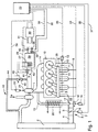
- an exhaust gas turbocharger 1 draws in fresh air on its compressor inlet side in accordance with arrow a.
- another charging device for. B. a mechanical loader and / or a so-called
- the sucked-in fresh air flows through a heat exchanger 2, which serves as charge air cooler, at a correspondingly increased pressure, and reaches a throttle point 3 in an intake line 4 of a diesel engine 10.
- a throttle valve 5 is arranged, which via an actuator 6 can be actuated by an auxiliary actuator 7.
- the fresh air first passes through a suction pipe 16 and then reaches an air collection chamber 8, from where it is fed to the combustion areas of the diesel engine 10 via separate inlet ducts 9.
- Throttle valves 11 are arranged which, according to the exemplary embodiment, can be actuated by a servo-operated actuator 13 via a common actuator 12.
- Downstream of the diesel engine 10 are those during combustion Exhaust gases formed in an exhaust gas collection chamber 14 with a Exhaust gas recirculation line 15, which in the intake manifold 16, d. H. here after the throttle 3 and before the air collection chamber 8 in the Air intake line 4 opens.
- the exhaust gas recirculation line 15 upstream of the Throttle point 3 on the intake tract of the diesel engine 10 be connected.
- an exhaust gas recirculation valve 17 arranged via an actuator 18 by an auxiliary operator Actuator 19 is actuated.
- a heat exchanger 20 in heat exchange, so that optionally cooling of the recirculated exhaust gas is achieved can be.
- the turbine inlet cross-section and / or the turbine Exhaust gas volume flow flowing through is by means of a Actuator 21 changeable by an auxiliary operator Actuator 22 is actuated.
- a Actuator 21 changeable by an auxiliary operator Actuator 22 is actuated.
- After flowing through the Turbine of the exhaust gas turbocharger 1 is the exhaust gas according to the Arrow b fed to an exhaust gas purification device 28, which in Fig. 1 shown by a broken line Frame is marked and described in more detail below becomes.
- the diesel engine 10 is operated by an engine controller or Motor control 23 controlled or regulated, for which purpose this Lines with the corresponding units of the diesel engine 10 is connected. 1 is a line 24, for example shown, which the engine control with a Injection system 25 of the diesel engine 10 connects. Further Lines 34, 35, 36 and 37 connect the controller 23 to the Actuators 22, 13, 19 and 7.
- the exhaust gas purification device 28 has an adsorber or storage catalytic converter 29, which is preferably designed as a NO x storage catalytic converter. Furthermore, the exhaust gas purification device 28 comprises an oxidation catalytic converter 30 arranged upstream or downstream of the NO x storage catalytic converter 29.
- the two catalytic converters 29 and 30 are connected to one another by at least one possibly insulated pipe 31, which is, for example, air-gap or mat-insulated.
- a first ⁇ probe 32 is arranged in the exhaust line of the diesel engine 10, which is connected to the controller 23 via a corresponding signal line 33.
- a first temperature sensor 38 is arranged downstream of the storage catalytic converter 29 and is connected to the controller 23 via a signal line 39.
- a second ⁇ probe 40 and a second temperature sensor 41 are arranged upstream of the storage catalytic converter 29, which likewise communicate with the controller 23 in a corresponding manner.
- further ⁇ probes, not shown here, and temperature sensors can be accommodated in the exhaust line of the diesel engine 10.
- at least one NO x sensor 42 is provided, which communicates with the exhaust line downstream of the storage catalytic converter 29 and is also connected to the controller 23.
- a secondary air supply 43 can be provided be the fresh air via one to the exhaust line connected supply line 44 downstream of the diesel engine 10, here downstream of the turbocharger 1, and upstream of the Storage catalyst 29 introduces into the exhaust system.
- the amount of secondary air supplied is controllable Feed valve 45 adjustable, via a corresponding Control line 46 is connected to the engine control 23.
- the secondary air can, for example, from the pressure side of the Exhaust gas turbocharger 1 are branched.
- the Secondary air is available in another suitable way be put.
- the storage catalytic converter 29 can be equipped with a heating device 27 be equipped, which in Fig. 1 by one in the Storage catalyst symbolizes 29 integrated heating spiral is.
- control according to the invention works as follows:
- the controller 23 actuates the diesel engine 10 so that it is operated in a storage mode in which the diesel engine 10 operates in a stoichiometric manner. In such a lean operation, there is an excess of atmospheric oxygen for the combustion of the diesel fuel, so that ⁇ > 1 applies.
- the diesel engine 10 is operated in its storage mode with ⁇ values from 1.3 to 10, the change in the ⁇ value being able to be implemented by varying the amount of fuel injected.
- the exhaust gases of the diesel engine 10 are mainly salts with a relatively low chemical binding energy, usually NO x , and significantly fewer salts with a relatively high chemical binding energy, such as. B. SO x .
- both the NO x salts and the SO x salts are adsorbed by the storage catalytic converter 29.
- the storage capacity of the storage catalytic converter 29 decreases over time, so that the storage catalytic converter 29 must be regenerated.
- the point in time at which such a regeneration has to be carried out can be determined using computing models or, for example, using the NO x sensor 42.
- the controller 23 switches the actuation of the diesel engine 10 to a regeneration mode in which the diesel engine 10 works with a substoichiometric ratio of atmospheric oxygen and fuel.
- this Fat operation "cannot completely burn the injected fuel in the diesel engine 10, so that unburned fuel is still contained in the exhaust gas.
- the diesel engine 10 is operated in its regeneration mode, for example, with a ⁇ value of 0.85.
- the unburned fuel in Exhaust gas serves as a reducing agent, so that the exhaust gas supplied to the storage catalytic converter 29 has a reducing effect, and the nitrates stored in the storage catalytic converter 29 can be desorbed and transported away due to this reducing atmosphere Since the sulfates have a higher chemical binding energy than the nitrates, they are thermodynamically more stable, so that during the denitrification or denitration in the regeneration mode there is virtually no desorption of the SO x salts, which are occupied by the sulfates However, the surface of the storage catalytic converter 29 is no longer available for storing the nitrates.
- the controller 23 decides that desulfurization or desulfation of the NO x storage catalytic converter 29 must be carried out.
- the controller 23 Before such a desulfation, the controller 23 first a denitration by the operation of the Diesel engine 10 is switched to the regeneration mode.
- the controller 23 switches diesel engine operation either directly on one Desalination mode or initially back to storage mode and then to desalination mode.
- this Desalination mode is the storage catalytic converter 29 alternately reducing exhaust gas and oxidizing exhaust gas fed.
- the ⁇ values are always in fat mode in the desalination mode are greater than the ⁇ values in the rich mode of the Regeneration mode.
- the ⁇ values are in the Lean operation of the desalination mode is always less than the ⁇ values in lean mode of storage mode.
- To im Storage catalytic converter 29 can increase the temperature for example, the heating coil 27 can be activated.
- it is possible through a targeted late post-injection of Fuel an increase in temperature in the exhaust system, to generate in particular in the storage catalytic converter 29.
- the alternating one Alternation between oxidizing exhaust gas and reducing acting exhaust gas can be achieved in that the diesel engine 10 is operated permanently in the desalination mode, where alternately the secondary air supply 43 is switched on and is switched off. With secondary air supply switched on 43 is then so much atmospheric oxygen in the rich exhaust gas initiated that upstream of the storage catalyst 29th gives a lean exhaust gas composition.
- This alternating reducing and oxidizing atmosphere at an overall elevated temperature in the storage catalytic converter 29 makes it possible to reduce the salts in the reduction phases and to oxidize them in the oxidation phases. Harmful secondary emissions, such as B. H 2 S can be avoided. It is clear that the storage catalytic converter 29 also has an oxidation and reduction function or reducing and oxidizing properties to some extent in order to implement the above-described reduction and oxidation processes.
Landscapes
- Engineering & Computer Science (AREA)
- Chemical & Material Sciences (AREA)
- Combustion & Propulsion (AREA)
- Mechanical Engineering (AREA)
- General Engineering & Computer Science (AREA)
- Exhaust Gas After Treatment (AREA)
Applications Claiming Priority (2)
| Application Number | Priority Date | Filing Date | Title |
|---|---|---|---|
| DE19939988 | 1999-08-24 | ||
| DE19939988A DE19939988A1 (de) | 1999-08-24 | 1999-08-24 | Verfahren zum Betreiben eines Dieselmotors |
Publications (3)
| Publication Number | Publication Date |
|---|---|
| EP1079079A2 true EP1079079A2 (fr) | 2001-02-28 |
| EP1079079A3 EP1079079A3 (fr) | 2003-02-12 |
| EP1079079B1 EP1079079B1 (fr) | 2004-03-03 |
Family
ID=7919350
Family Applications (1)
| Application Number | Title | Priority Date | Filing Date |
|---|---|---|---|
| EP00113356A Expired - Lifetime EP1079079B1 (fr) | 1999-08-24 | 2000-06-23 | Commande de moteur pour un moteur diesel |
Country Status (3)
| Country | Link |
|---|---|
| EP (1) | EP1079079B1 (fr) |
| DE (2) | DE19939988A1 (fr) |
| ES (1) | ES2215524T3 (fr) |
Cited By (2)
| Publication number | Priority date | Publication date | Assignee | Title |
|---|---|---|---|---|
| WO2003048537A1 (fr) * | 2001-11-28 | 2003-06-12 | Robert Bosch Gmbh | Procede permettant de faire fonctionner un moteur a combustion interne et moteur a combustion interne associe |
| EP1510672A1 (fr) * | 2003-08-26 | 2005-03-02 | Ford Global Technologies, LLC | Arrangement de capteur d'oxygène |
Families Citing this family (5)
| Publication number | Priority date | Publication date | Assignee | Title |
|---|---|---|---|---|
| US7293407B2 (en) | 2000-06-21 | 2007-11-13 | Daimlerchrysler Ag | Method for operating a diesel engine |
| DE10029504C2 (de) * | 2000-06-21 | 2003-04-30 | Daimler Chrysler Ag | Verfahren zum Betrieb eines Dieselmotors |
| DE10153901B4 (de) * | 2001-10-12 | 2011-07-14 | Volkswagen AG, 38440 | Verfahren und Vorrichtung zur Entschwefelung eines einem Dieselmotor nachgeschalteten NOx-Speicherkatalysators |
| DE10248734B4 (de) * | 2002-10-18 | 2004-10-28 | Litef Gmbh | Verfahren zur elektronischen Abstimmung der Ausleseschwingungsfrequenz eines Corioliskreisels |
| DE102004052062A1 (de) * | 2004-10-26 | 2006-04-27 | Volkswagen Ag | Verfahren und Vorrichtung zur Regenerierung von Speicherkatalysatoren |
Citations (1)
| Publication number | Priority date | Publication date | Assignee | Title |
|---|---|---|---|---|
| DE19750226C1 (de) | 1997-11-13 | 1998-10-29 | Daimler Benz Ag | Motorregelsystem für einen Dieselmotor |
Family Cites Families (6)
| Publication number | Priority date | Publication date | Assignee | Title |
|---|---|---|---|---|
| JP2605586B2 (ja) * | 1992-07-24 | 1997-04-30 | トヨタ自動車株式会社 | 内燃機関の排気浄化装置 |
| DE19731623B4 (de) * | 1997-07-23 | 2006-11-23 | Volkswagen Ag | Verfahren und Vorrichtung zur De-Sulfatierung von NOx-Speichern bei Dieselmotoren |
| US5974788A (en) * | 1997-08-29 | 1999-11-02 | Ford Global Technologies, Inc. | Method and apparatus for desulfating a nox trap |
| DE19920515C2 (de) * | 1999-05-05 | 2003-03-20 | Daimler Chrysler Ag | Abgasreinigungsanlage mit Stickoxidadsorber und Desulfatisierungsverfahren hierfür |
| DE19922962C2 (de) * | 1999-05-19 | 2003-02-27 | Daimler Chrysler Ag | Verfahren zur periodischen Desulfatisierung eines Stickoxid- oder Schwefeloxid-Speichers einer Abgasreinigungsanlage |
| DE19923481A1 (de) * | 1999-05-21 | 2000-11-23 | Volkswagen Ag | Verfahren zur Entschwefelung von wenigstens einem in einem Abgaskanal einer Verbrennungskraftmaschine angeordneten NOx-Speicherkatalysator |
-
1999
- 1999-08-24 DE DE19939988A patent/DE19939988A1/de not_active Ceased
-
2000
- 2000-06-23 EP EP00113356A patent/EP1079079B1/fr not_active Expired - Lifetime
- 2000-06-23 DE DE50005490T patent/DE50005490D1/de not_active Expired - Lifetime
- 2000-06-23 ES ES00113356T patent/ES2215524T3/es not_active Expired - Lifetime
Patent Citations (1)
| Publication number | Priority date | Publication date | Assignee | Title |
|---|---|---|---|---|
| DE19750226C1 (de) | 1997-11-13 | 1998-10-29 | Daimler Benz Ag | Motorregelsystem für einen Dieselmotor |
Cited By (2)
| Publication number | Priority date | Publication date | Assignee | Title |
|---|---|---|---|---|
| WO2003048537A1 (fr) * | 2001-11-28 | 2003-06-12 | Robert Bosch Gmbh | Procede permettant de faire fonctionner un moteur a combustion interne et moteur a combustion interne associe |
| EP1510672A1 (fr) * | 2003-08-26 | 2005-03-02 | Ford Global Technologies, LLC | Arrangement de capteur d'oxygène |
Also Published As
| Publication number | Publication date |
|---|---|
| DE19939988A1 (de) | 2001-03-15 |
| EP1079079B1 (fr) | 2004-03-03 |
| ES2215524T3 (es) | 2004-10-16 |
| DE50005490D1 (de) | 2004-04-08 |
| EP1079079A3 (fr) | 2003-02-12 |
Similar Documents
| Publication | Publication Date | Title |
|---|---|---|
| DE69205389T2 (de) | Einrichtung zur Minderung von Stickoxiden in Rauchgasen aus Brennkraftmaschinen. | |
| EP3502428B1 (fr) | Système de post-traitement des gaz d'échappement et procédé de post-traitement des gaz d'échappement d'un moteur à combustion interne | |
| EP0913558B1 (fr) | Dispositif d'épuration des gaz d'échappement d'un moteur à combustion interne | |
| DE102011101079B4 (de) | Verfahren zur Regeneration von NOx-Speicherkatalysatoren von Dieselmotoren mit Niederdruck-AGR | |
| EP0931922B1 (fr) | Procédé et dispositif d' épuration de gaz d' échappement d'un moteur à combustion interne | |
| DE60300270T2 (de) | Abgaskontrollsystem für eine Diesel Brennkraftmaschine und Regelverfahren dafür | |
| DE10040554B4 (de) | Verfahren zum Betrieb einer Abgasreinigungsanlage mit Partikelfilter und Stickoxidspeicher | |
| EP1630394A2 (fr) | Moteur Diesel | |
| DE102015212514A1 (de) | Verfahren zur Abgasnachbehandlung und Vorrichtung zur Reinigung des Abgases einer Brennkraftmaschine | |
| EP1086741B1 (fr) | Procédé pour commander la régénération d'un filtre à particules et la désulfuration d'un catalyseur d'accumulation des oxydes d'azote | |
| WO2005049984A1 (fr) | Moteur a combustion interne comportant un systeme de purification des gaz d'echappement, et procede de purification des gaz d'echappement d'un moteur a combustion interne | |
| EP2525066B1 (fr) | Procédé et dispositif de désulfatation d'un dispositif de nettoyage des gaz d'échappement agencé dans un moteur à combustion diesel | |
| DE102016205182A1 (de) | Verfahren und Vorrichtung zur Abgasnachbehandlung eines Verbrennungsmotors | |
| EP1079079B1 (fr) | Commande de moteur pour un moteur diesel | |
| DE19959605A1 (de) | Vorrichtung und Verfahren zur NOx- und/oder SOx-Regeneration eines NOx-Speicherkatalysators | |
| DE102009021114A1 (de) | Verfahren zum Betreiben einer luftverdichtenden Brennkraftmaschine | |
| DE10003903B4 (de) | Vorrichtung und Verfahren zur Steuerung eines Betriebes eines Mehrzylindermotors für Kraftfahrzeuge mit einer mehrflutigen Abgasreinigungsanlage | |
| DE102016210897B4 (de) | Steuerung einer Stickoxidemission in Betriebsphasen hoher Last | |
| DE102018203300B4 (de) | Anordnung einer Brennkraftmaschine mit einem Abgastrakt, Kraftfahrzeug sowie Verfahren zum Steuern einer Abgasnachbehandlung | |
| DE10018062A1 (de) | Mehrzylindermotor für Kraftfahrzeuge mit einer mehrflutigen Abgasreinigungsanlage und Verfahren zur Steuerung eines Betriebs des Mehrzylindermotors | |
| DE102009014360A1 (de) | Verfahren zur Regeneration eines Stickoxid-Speicherkatalysators | |
| DE102017201399B4 (de) | Abgasnachbehandlungssystem | |
| DE102019116774A1 (de) | Verfahren zum Betrieb einer Abgasnachbehandlungseinrichtung, Steuereinheit für eine Brennkraftmaschine und Brennkraftmaschine | |
| DE19933736B4 (de) | Anordnung und Verfahren zur Reinigung eines Abgases einer Verbrennungskraftmaschine | |
| DE10038458A1 (de) | Vorrichtung und Verfahren zur Abgasreinigung |
Legal Events
| Date | Code | Title | Description |
|---|---|---|---|
| PUAI | Public reference made under article 153(3) epc to a published international application that has entered the european phase |
Free format text: ORIGINAL CODE: 0009012 |
|
| AK | Designated contracting states |
Kind code of ref document: A2 Designated state(s): AT BE CH CY DE DK ES FI FR GB GR IE IT LI LU MC NL PT SE |
|
| AX | Request for extension of the european patent |
Free format text: AL;LT;LV;MK;RO;SI |
|
| PUAL | Search report despatched |
Free format text: ORIGINAL CODE: 0009013 |
|
| AK | Designated contracting states |
Designated state(s): AT BE CH CY DE DK ES FI FR GB GR IE IT LI LU MC NL PT SE |
|
| AX | Request for extension of the european patent |
Extension state: AL LT LV MK RO SI |
|
| RIC1 | Information provided on ipc code assigned before grant |
Ipc: 7F 01N 3/08 A Ipc: 7F 02D 41/02 B |
|
| 17P | Request for examination filed |
Effective date: 20030124 |
|
| 17Q | First examination report despatched |
Effective date: 20030328 |
|
| GRAP | Despatch of communication of intention to grant a patent |
Free format text: ORIGINAL CODE: EPIDOSNIGR1 |
|
| RTI1 | Title (correction) |
Free format text: ENGINE CONTROL SYSTEM FOR A DIESEL ENGINE |
|
| AKX | Designation fees paid |
Designated state(s): DE ES FR GB IT |
|
| GRAS | Grant fee paid |
Free format text: ORIGINAL CODE: EPIDOSNIGR3 |
|
| GRAA | (expected) grant |
Free format text: ORIGINAL CODE: 0009210 |
|
| AK | Designated contracting states |
Kind code of ref document: B1 Designated state(s): DE ES FR GB IT |
|
| REG | Reference to a national code |
Ref country code: GB Ref legal event code: FG4D Free format text: NOT ENGLISH |
|
| REG | Reference to a national code |
Ref country code: IE Ref legal event code: FG4D Free format text: GERMAN |
|
| REF | Corresponds to: |
Ref document number: 50005490 Country of ref document: DE Date of ref document: 20040408 Kind code of ref document: P |
|
| GBT | Gb: translation of ep patent filed (gb section 77(6)(a)/1977) |
Effective date: 20040322 |
|
| REG | Reference to a national code |
Ref country code: ES Ref legal event code: FG2A Ref document number: 2215524 Country of ref document: ES Kind code of ref document: T3 |
|
| REG | Reference to a national code |
Ref country code: IE Ref legal event code: FD4D |
|
| ET | Fr: translation filed | ||
| PLBE | No opposition filed within time limit |
Free format text: ORIGINAL CODE: 0009261 |
|
| STAA | Information on the status of an ep patent application or granted ep patent |
Free format text: STATUS: NO OPPOSITION FILED WITHIN TIME LIMIT |
|
| 26N | No opposition filed |
Effective date: 20041206 |
|
| REG | Reference to a national code |
Ref country code: FR Ref legal event code: CA Ref country code: FR Ref legal event code: CD |
|
| PGFP | Annual fee paid to national office [announced via postgrant information from national office to epo] |
Ref country code: IT Payment date: 20120621 Year of fee payment: 13 |
|
| PGFP | Annual fee paid to national office [announced via postgrant information from national office to epo] |
Ref country code: ES Payment date: 20120717 Year of fee payment: 13 |
|
| PG25 | Lapsed in a contracting state [announced via postgrant information from national office to epo] |
Ref country code: IT Free format text: LAPSE BECAUSE OF NON-PAYMENT OF DUE FEES Effective date: 20130623 |
|
| REG | Reference to a national code |
Ref country code: ES Ref legal event code: FD2A Effective date: 20141014 |
|
| PG25 | Lapsed in a contracting state [announced via postgrant information from national office to epo] |
Ref country code: ES Free format text: LAPSE BECAUSE OF NON-PAYMENT OF DUE FEES Effective date: 20130624 |
|
| REG | Reference to a national code |
Ref country code: FR Ref legal event code: PLFP Year of fee payment: 17 |
|
| REG | Reference to a national code |
Ref country code: FR Ref legal event code: PLFP Year of fee payment: 18 |
|
| REG | Reference to a national code |
Ref country code: FR Ref legal event code: PLFP Year of fee payment: 19 |
|
| PGFP | Annual fee paid to national office [announced via postgrant information from national office to epo] |
Ref country code: FR Payment date: 20180629 Year of fee payment: 19 |
|
| PGFP | Annual fee paid to national office [announced via postgrant information from national office to epo] |
Ref country code: DE Payment date: 20180831 Year of fee payment: 19 Ref country code: GB Payment date: 20180629 Year of fee payment: 19 |
|
| REG | Reference to a national code |
Ref country code: DE Ref legal event code: R119 Ref document number: 50005490 Country of ref document: DE |
|
| GBPC | Gb: european patent ceased through non-payment of renewal fee |
Effective date: 20190623 |
|
| PG25 | Lapsed in a contracting state [announced via postgrant information from national office to epo] |
Ref country code: GB Free format text: LAPSE BECAUSE OF NON-PAYMENT OF DUE FEES Effective date: 20190623 Ref country code: DE Free format text: LAPSE BECAUSE OF NON-PAYMENT OF DUE FEES Effective date: 20200101 |
|
| PG25 | Lapsed in a contracting state [announced via postgrant information from national office to epo] |
Ref country code: FR Free format text: LAPSE BECAUSE OF NON-PAYMENT OF DUE FEES Effective date: 20190630 |