EP1079129A2 - Soufflet d' étanchéité pour joint homocinétique - Google Patents
Soufflet d' étanchéité pour joint homocinétique Download PDFInfo
- Publication number
- EP1079129A2 EP1079129A2 EP00118393A EP00118393A EP1079129A2 EP 1079129 A2 EP1079129 A2 EP 1079129A2 EP 00118393 A EP00118393 A EP 00118393A EP 00118393 A EP00118393 A EP 00118393A EP 1079129 A2 EP1079129 A2 EP 1079129A2
- Authority
- EP
- European Patent Office
- Prior art keywords
- crest
- root
- constant velocity
- velocity joint
- root portion
- Prior art date
- Legal status (The legal status is an assumption and is not a legal conclusion. Google has not performed a legal analysis and makes no representation as to the accuracy of the status listed.)
- Granted
Links
Images


Classifications
-
- F—MECHANICAL ENGINEERING; LIGHTING; HEATING; WEAPONS; BLASTING
- F16—ENGINEERING ELEMENTS AND UNITS; GENERAL MEASURES FOR PRODUCING AND MAINTAINING EFFECTIVE FUNCTIONING OF MACHINES OR INSTALLATIONS; THERMAL INSULATION IN GENERAL
- F16D—COUPLINGS FOR TRANSMITTING ROTATION; CLUTCHES; BRAKES
- F16D3/00—Yielding couplings, i.e. with means permitting movement between the connected parts during the drive
- F16D3/84—Shrouds, e.g. casings, covers; Sealing means specially adapted therefor
- F16D3/843—Shrouds, e.g. casings, covers; Sealing means specially adapted therefor enclosed covers
- F16D3/845—Shrouds, e.g. casings, covers; Sealing means specially adapted therefor enclosed covers allowing relative movement of joint parts due to the flexing of the cover
-
- F—MECHANICAL ENGINEERING; LIGHTING; HEATING; WEAPONS; BLASTING
- F16—ENGINEERING ELEMENTS AND UNITS; GENERAL MEASURES FOR PRODUCING AND MAINTAINING EFFECTIVE FUNCTIONING OF MACHINES OR INSTALLATIONS; THERMAL INSULATION IN GENERAL
- F16J—PISTONS; CYLINDERS; SEALINGS
- F16J3/00—Diaphragms; Bellows; Bellows pistons
- F16J3/04—Bellows
- F16J3/041—Non-metallic bellows
-
- B—PERFORMING OPERATIONS; TRANSPORTING
- B29—WORKING OF PLASTICS; WORKING OF SUBSTANCES IN A PLASTIC STATE IN GENERAL
- B29L—INDEXING SCHEME ASSOCIATED WITH SUBCLASS B29C, RELATING TO PARTICULAR ARTICLES
- B29L2031/00—Other particular articles
- B29L2031/703—Bellows
Definitions
- the present invention relates to a boot covering a constant velocity joint that is indispensably used for a joint of a drive shaft used in a front drive vehicle in order to prevent water or dust from entering into a joint portion of the constant velocity joint.
- the constant velocity joint boot comprises a first cylindrical portion of a large diameter being held by a joint outer race or the like, a second cylindrical portion of a smaller diameter than the first cylindrical portion and being held by a shaft, and a bellowed portion in the shape of a generally truncated triangular pyramid for integrally connecting the first cylindrical portion and the second cylindrical portion.
- the bellowed portion of the conventional boot constant velocity joint is formed with crests and roots continuing alternately and respective crests and roots are generally formed in geometrical similarity.
- the outer diameters of the crest portions are relatively large in order to grease the way to accommodate variations in the angle defined between the central axis of a joint outer race or the like and the central axis of a shaft and reduce stresses generated at the bellowed portion.
- miniaturization of the constant velocity joint boots is also asked for in conjunction with miniaturization of vehicles.
- the bellowed portion comprises a plurality of crest portions and root portions arranged in such a manner as, from the side of the first cylindrical portion, a first root portion, a first crest portion, a second root portion, a second crest portion, a third root portion, etc, continuously and alternately, and the outer diameter of the first crest portion is almost the same as that of the first cylindrical portion.
- the outer diameter of the crest portions become smaller gradually from the second crest portion on, forming a shape of generally truncated triangular pyramid.
- the length of the line connecting the top of the first crest portion through the second root portion to the second crest portion is almost the same as that of the line connecting the top of the second crest portion through the third root portion to the top of the third crest portion.
- the length of the membrane extending between the first crest portion and the second crest portion is almost the same as that extending between the second crest portion and the third crest portion. Therefore, a sufficient amount of deformation may be ensured within the range from the first crest portion through the second root portion, the second crest portion, the third root portion, and the third crest portion where a large amount of deformation is expected as a constant velocity joint boot.
- the length of the membrane extending between any adjacent crest portions is also preferable to make the length of the membrane extending between any adjacent crest portions the same length respectively. If there is a portion where the length of membrane is relatively short, there may be a recognized disadvantage that the fatigue resisting property is degraded because the portion is subject to a significant stress. Provided that the length of membrane in the vicinity of the crest portion of the smallest diameter located adjacent the second cylindrical portion is excluded since the amount of deformation is quite small around this portion.
- the depth of the second root portion (h) and the depth of the third root portion (H) satisfy the relational expression: H/1.3 ⁇ h ⁇ H/1.1
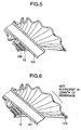
- a jam of the second root portion may be prevented even when the angle defined by a pair of axes of rotation is increased to about 50 degrees.
- the depth of the second root portion (h) is below H/1.3, it will be difficult to ensure a sufficient amount of deformation because the length of membrane of the second root portion is too short, and thus leading to degradation of the fatigue resisting property thereof.
- the depth (h) of the second root portion is over H/1.1, a jam may occur at the second root portion.
- the length of the membrane from the first crest portion through the second root portion to the second crest portion is almost the same as that from the second crest portion through the third root portion to the third crest portion.
- the angle at the second root portion is larger than that at the third root portion.
- the constant velocity joint boot of the present invention does not suffer from a jam even when the angle defined by a pair of axes of rotation is significantly large such as 50 degrees or so, and thus degradation of sealing property caused by damage thereof is prevented with reliability. Therefore, the boot may have long lasting qualities.
- the constant velocity joint boot of the present invention may have the same structure as conventional boot.
- thermoplastic elastomer or the like which may be formed generally by blow molding may be employed.
- the number of the crest portions and the root portions and the thickness thereof may be selected according to the application.
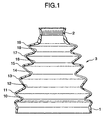
- Fig. 1 is a cross sectional view of a constant velocity joint boot according to the present embodiment
- Fig. 2 is an enlarged view of the principal portion of the constant velocity joint boot of Fig. 1.
- the constant velocity joint boot comprises a first cylindrical portion 1, the second cylindrical portion 2 having smaller diameter than the first cylindrical portion 1, and the bellowed portion 3 in the shape of a generally truncated triangular pyramid for integrally connecting the first cylindrical portion 1 and the second cylindrical portion 2.
- the first cylindrical portion 1 and the bellowed portion 3 are formed of thermoplastic elastomer by blow molding
- the second cylindrical portion 2 is formed of thermoplastic elastomer integrally with the bellowed portion by injection molding.
- the bellowed portion 3 comprises, from the side of the first cylindrical portion, a first root portion 10, a first crest portion 11, a second root portion 12, a second crest portion 13, a third root portion 14, a third crest portion 15, a forth root portion 16, a forth crest portion 17, a fifth root portion 18, and a fifth crest portion 19.
- the crest portions and the root portions are formed alternately, and the line connecting the tops of respective crest portions is a straight line so that the bellowed portion has a shape of a generally truncated triangular pyramid formed in such a manner that a first crest portion 11 has a largest diameter and the fifth crest portion 19 has a smallest diameter.
- the outer diameter of the first crest portion 11 is the same as the largest outer diameter of the first cylindrical portion 1.
- the length of the line (P1-P2-P3) connecting the top of the first crest portion 11 (P1) through the bottom of the second root portion 12 (P2) to the top of the second crest portion 13 (P3) is the same as that of the line (P3-P4-P5) connecting the top of the second crest portion 13 (P3) through the bottom of the third root portion 14 (P4) to the top of the third crest portion 15 (P5).
- the length of the membrane extending from the first crest portion 11 through the second root portion 12 to the second crest portion 13 is the same as the length of the membrane extending from the second crest portion 13 through the third root portion 15 to the third crest portion 15.
- the bellowed portion is so designed that the length of the membrane from any crest portion to an adjacent crest portion and the length of the next portion corresponding thereto are almost the same, except for the length of membrane from the fourth crest portion 17 through the fifth root portion 18 to the fifth crest portion 19.
- the angle ⁇ 1 of the second root portion 12 is substantially 110 degrees, which is larger than that of the preferred embodiment.
- the first cylindrical portion 1 is fixed to the outer peripheral surface of the joint outer race 100 by a snap ring which is not shown
- the second cylindrical portion 2 is fixed to the outer peripheral surface of the drive shaft 101 by a snap ring which is not shown.
- a jam of the root portions may be reliably prevented with the fatigue resisting property thereof maintained as it was conventionally, and with its dimensions reduced, and therefore long lasting qualities may be achieved.
Landscapes
- Engineering & Computer Science (AREA)
- General Engineering & Computer Science (AREA)
- Mechanical Engineering (AREA)
- Diaphragms And Bellows (AREA)
- Sealing Devices (AREA)
Applications Claiming Priority (2)
| Application Number | Priority Date | Filing Date | Title |
|---|---|---|---|
| JP23940899A JP3644584B2 (ja) | 1999-08-26 | 1999-08-26 | 等速ジョイント用ブーツ |
| JP23940899 | 1999-08-26 |
Publications (3)
| Publication Number | Publication Date |
|---|---|
| EP1079129A2 true EP1079129A2 (fr) | 2001-02-28 |
| EP1079129A3 EP1079129A3 (fr) | 2001-05-02 |
| EP1079129B1 EP1079129B1 (fr) | 2005-05-11 |
Family
ID=17044339
Family Applications (1)
| Application Number | Title | Priority Date | Filing Date |
|---|---|---|---|
| EP00118393A Expired - Lifetime EP1079129B1 (fr) | 1999-08-26 | 2000-08-24 | Soufflet d' étanchéité pour joint homocinétique |
Country Status (4)
| Country | Link |
|---|---|
| US (1) | US6478309B1 (fr) |
| EP (1) | EP1079129B1 (fr) |
| JP (1) | JP3644584B2 (fr) |
| DE (1) | DE60020030T2 (fr) |
Families Citing this family (9)
| Publication number | Priority date | Publication date | Assignee | Title |
|---|---|---|---|---|
| JP2001171308A (ja) * | 1999-12-15 | 2001-06-26 | Ntn Corp | 駆動車輪用軸受装置 |
| JP2003004063A (ja) * | 2001-04-20 | 2003-01-08 | Toyoda Gosei Co Ltd | 等速ジョイント用ブーツ |
| CN101087850A (zh) * | 2004-12-24 | 2007-12-12 | Nok株式会社 | 热塑性弹性体共混物 |
| JP2007030818A (ja) * | 2005-07-29 | 2007-02-08 | Toyoda Gosei Co Ltd | ラックブーツ |
| JP4832837B2 (ja) * | 2005-09-16 | 2011-12-07 | Ntn株式会社 | 等速自在継手用ブーツ |
| US7468000B2 (en) * | 2006-01-12 | 2008-12-23 | Delphi Technologies, Inc. | Boot for universal joint |
| WO2008058559A1 (fr) * | 2006-11-16 | 2008-05-22 | Gkn Driveline International Gmbh | Soufflet destiné à assurer l'étanchéité d'une fente annulaire |
| US8162767B2 (en) * | 2008-05-23 | 2012-04-24 | Steering Solutions IP Holding Company | Boot for a constant velocity joint |
| US8192111B2 (en) * | 2009-05-20 | 2012-06-05 | Gse Lining Technology, Inc. | Boot for geosynthetic layer |
Family Cites Families (10)
| Publication number | Priority date | Publication date | Assignee | Title |
|---|---|---|---|---|
| JPS61244925A (ja) * | 1985-04-19 | 1986-10-31 | Toyoda Gosei Co Ltd | 等速形軸継手用ブーツ |
| JPS6252220A (ja) * | 1985-08-31 | 1987-03-06 | Toyoda Gosei Co Ltd | 機械軸継手用ブ−ツ |
| DE3639482A1 (de) | 1986-11-18 | 1988-05-26 | Wolfram Dr Schiemann | Faltenbalg fuer kraftfahrzeuge |
| US4923432A (en) * | 1989-02-10 | 1990-05-08 | Moog Automotive, Inc. | Flexible boot for driving axle joints |
| GB2295426B (en) * | 1994-11-10 | 1998-07-01 | Draftex Ind Ltd | Protective bellows |
| JP3725919B2 (ja) | 1995-09-26 | 2005-12-14 | キーパー株式会社 | 樹脂製cvjブーツ |
| JPH10299788A (ja) | 1997-04-25 | 1998-11-10 | Ntn Corp | 等速ジョイント用フレキシブルブーツ |
| JPH10299789A (ja) | 1997-04-25 | 1998-11-10 | Ntn Corp | 等速ジョイント用フレキシブルブーツ |
| US6099788A (en) * | 1997-12-19 | 2000-08-08 | Salflex Polymers Ltd. | Method of making a protective boot for an automotive component |
| US6089574A (en) * | 1998-03-11 | 2000-07-18 | Salflex Polymers Ltd. | Boot with insertable bushing |
-
1999
- 1999-08-26 JP JP23940899A patent/JP3644584B2/ja not_active Expired - Fee Related
-
2000
- 2000-08-18 US US09/640,911 patent/US6478309B1/en not_active Expired - Lifetime
- 2000-08-24 DE DE60020030T patent/DE60020030T2/de not_active Expired - Lifetime
- 2000-08-24 EP EP00118393A patent/EP1079129B1/fr not_active Expired - Lifetime
Also Published As
| Publication number | Publication date |
|---|---|
| JP2001065594A (ja) | 2001-03-16 |
| EP1079129B1 (fr) | 2005-05-11 |
| EP1079129A3 (fr) | 2001-05-02 |
| US6478309B1 (en) | 2002-11-12 |
| DE60020030T2 (de) | 2006-03-09 |
| DE60020030D1 (de) | 2005-06-16 |
| JP3644584B2 (ja) | 2005-04-27 |
Similar Documents
| Publication | Publication Date | Title |
|---|---|---|
| US7641563B2 (en) | Boot for constant-velocity universal joint | |
| EP1079129B1 (fr) | Soufflet d' étanchéité pour joint homocinétique | |
| US6695706B2 (en) | Constant velocity joint boot | |
| US5251916A (en) | Flexible boot for universal joint | |
| US7753380B2 (en) | Boot for constant-velocity universal joint | |
| EP1233195B1 (fr) | Joint pour articulation à rotule | |
| US7097568B2 (en) | Shielded sealing system for a constant velocity joint | |
| US6715771B2 (en) | Boot for constant velocity universal joint | |
| US20100160053A1 (en) | Boot for universal joint | |
| EP1293692A1 (fr) | Soufflet d'étanchéité fabriqué en résine | |
| US20090048029A1 (en) | Boot for universal joint | |
| US7445557B2 (en) | Constant velocity joint boot | |
| CA2119119C (fr) | Manchon a circonvolutions externes pour joint homocinetique | |
| EP2241774B1 (fr) | Soufflet de protection pour joint universel homocinétique | |
| JP2002295509A (ja) | 等速ジョイント用ブーツ | |
| JP2004360817A (ja) | 等速ジョイント用ブーツ | |
| JP2012017844A (ja) | 固定式等速自在継手及び等速自在継手用ブーツ | |
| JP2002039383A (ja) | ブーツ取付構造 | |
| US8348774B2 (en) | Constant velocity joint and constant velocity joint boot | |
| EP3686447B1 (fr) | Joint à rotule et capot anti-poussière | |
| JP2009085282A (ja) | 等速ジョイント用ブーツ | |
| JP2007211927A (ja) | 等速自在継手用ブーツ | |
| EP1975476A1 (fr) | Bande pour joint universel à vitesse constante et sa structure de fixation | |
| JPH0547851Y2 (fr) | ||
| CA2488666C (fr) | Protecteur pour joint homocinetique |
Legal Events
| Date | Code | Title | Description |
|---|---|---|---|
| PUAI | Public reference made under article 153(3) epc to a published international application that has entered the european phase |
Free format text: ORIGINAL CODE: 0009012 |
|
| 17P | Request for examination filed |
Effective date: 20000824 |
|
| AK | Designated contracting states |
Kind code of ref document: A2 Designated state(s): DE FR GB |
|
| AX | Request for extension of the european patent |
Free format text: AL;LT;LV;MK;RO;SI |
|
| PUAL | Search report despatched |
Free format text: ORIGINAL CODE: 0009013 |
|
| AK | Designated contracting states |
Kind code of ref document: A3 Designated state(s): AT BE CH CY DE DK ES FI FR GB GR IE IT LI LU MC NL PT SE |
|
| AX | Request for extension of the european patent |
Free format text: AL;LT;LV;MK;RO;SI |
|
| AKX | Designation fees paid |
Free format text: DE FR GB |
|
| GRAP | Despatch of communication of intention to grant a patent |
Free format text: ORIGINAL CODE: EPIDOSNIGR1 |
|
| GRAS | Grant fee paid |
Free format text: ORIGINAL CODE: EPIDOSNIGR3 |
|
| GRAA | (expected) grant |
Free format text: ORIGINAL CODE: 0009210 |
|
| RIN1 | Information on inventor provided before grant (corrected) |
Inventor name: MIYAMOTO, KENJI Inventor name: FURUTA, YUJI |
|
| AK | Designated contracting states |
Kind code of ref document: B1 Designated state(s): DE FR GB |
|
| REG | Reference to a national code |
Ref country code: GB Ref legal event code: FG4D |
|
| REF | Corresponds to: |
Ref document number: 60020030 Country of ref document: DE Date of ref document: 20050616 Kind code of ref document: P |
|
| ET | Fr: translation filed | ||
| PLBE | No opposition filed within time limit |
Free format text: ORIGINAL CODE: 0009261 |
|
| STAA | Information on the status of an ep patent application or granted ep patent |
Free format text: STATUS: NO OPPOSITION FILED WITHIN TIME LIMIT |
|
| 26N | No opposition filed |
Effective date: 20060214 |
|
| REG | Reference to a national code |
Ref country code: GB Ref legal event code: 746 Effective date: 20120709 |
|
| REG | Reference to a national code |
Ref country code: DE Ref legal event code: R084 Ref document number: 60020030 Country of ref document: DE Effective date: 20120627 |
|
| REG | Reference to a national code |
Ref country code: FR Ref legal event code: PLFP Year of fee payment: 17 |
|
| REG | Reference to a national code |
Ref country code: FR Ref legal event code: PLFP Year of fee payment: 18 |
|
| REG | Reference to a national code |
Ref country code: FR Ref legal event code: PLFP Year of fee payment: 19 |
|
| PGFP | Annual fee paid to national office [announced via postgrant information from national office to epo] |
Ref country code: DE Payment date: 20190813 Year of fee payment: 20 Ref country code: FR Payment date: 20190711 Year of fee payment: 20 |
|
| PGFP | Annual fee paid to national office [announced via postgrant information from national office to epo] |
Ref country code: GB Payment date: 20190822 Year of fee payment: 20 |
|
| REG | Reference to a national code |
Ref country code: DE Ref legal event code: R071 Ref document number: 60020030 Country of ref document: DE |
|
| REG | Reference to a national code |
Ref country code: GB Ref legal event code: PE20 Expiry date: 20200823 |
|
| PG25 | Lapsed in a contracting state [announced via postgrant information from national office to epo] |
Ref country code: GB Free format text: LAPSE BECAUSE OF EXPIRATION OF PROTECTION Effective date: 20200823 |