EP1079148B1 - Différentiel à pignons coniques pour véhicules automobiles - Google Patents
Différentiel à pignons coniques pour véhicules automobiles Download PDFInfo
- Publication number
- EP1079148B1 EP1079148B1 EP19990116200 EP99116200A EP1079148B1 EP 1079148 B1 EP1079148 B1 EP 1079148B1 EP 19990116200 EP19990116200 EP 19990116200 EP 99116200 A EP99116200 A EP 99116200A EP 1079148 B1 EP1079148 B1 EP 1079148B1
- Authority
- EP
- European Patent Office
- Prior art keywords
- differential
- drive
- bolt
- cylindrical
- housing
- Prior art date
- Legal status (The legal status is an assumption and is not a legal conclusion. Google has not performed a legal analysis and makes no representation as to the accuracy of the status listed.)
- Expired - Lifetime
Links
- 238000013459 approach Methods 0.000 description 8
- 238000010276 construction Methods 0.000 description 3
- 230000005540 biological transmission Effects 0.000 description 2
- 238000005304 joining Methods 0.000 description 2
- 239000000314 lubricant Substances 0.000 description 2
- 238000004519 manufacturing process Methods 0.000 description 2
- 238000000926 separation method Methods 0.000 description 2
- 238000003754 machining Methods 0.000 description 1
- 238000012423 maintenance Methods 0.000 description 1
- 230000013011 mating Effects 0.000 description 1
- 238000003860 storage Methods 0.000 description 1
Images

Classifications
-
- F—MECHANICAL ENGINEERING; LIGHTING; HEATING; WEAPONS; BLASTING
- F16—ENGINEERING ELEMENTS AND UNITS; GENERAL MEASURES FOR PRODUCING AND MAINTAINING EFFECTIVE FUNCTIONING OF MACHINES OR INSTALLATIONS; THERMAL INSULATION IN GENERAL
- F16H—GEARING
- F16H48/00—Differential gearings
- F16H48/06—Differential gearings with gears having orbital motion
- F16H48/08—Differential gearings with gears having orbital motion comprising bevel gears
-
- F—MECHANICAL ENGINEERING; LIGHTING; HEATING; WEAPONS; BLASTING
- F16—ENGINEERING ELEMENTS AND UNITS; GENERAL MEASURES FOR PRODUCING AND MAINTAINING EFFECTIVE FUNCTIONING OF MACHINES OR INSTALLATIONS; THERMAL INSULATION IN GENERAL
- F16H—GEARING
- F16H48/00—Differential gearings
- F16H48/06—Differential gearings with gears having orbital motion
- F16H48/08—Differential gearings with gears having orbital motion comprising bevel gears
- F16H2048/085—Differential gearings with gears having orbital motion comprising bevel gears characterised by shafts or gear carriers for orbital gears
-
- F—MECHANICAL ENGINEERING; LIGHTING; HEATING; WEAPONS; BLASTING
- F16—ENGINEERING ELEMENTS AND UNITS; GENERAL MEASURES FOR PRODUCING AND MAINTAINING EFFECTIVE FUNCTIONING OF MACHINES OR INSTALLATIONS; THERMAL INSULATION IN GENERAL
- F16H—GEARING
- F16H48/00—Differential gearings
- F16H48/38—Constructional details
- F16H2048/385—Constructional details of the ring or crown gear
-
- F—MECHANICAL ENGINEERING; LIGHTING; HEATING; WEAPONS; BLASTING
- F16—ENGINEERING ELEMENTS AND UNITS; GENERAL MEASURES FOR PRODUCING AND MAINTAINING EFFECTIVE FUNCTIONING OF MACHINES OR INSTALLATIONS; THERMAL INSULATION IN GENERAL
- F16H—GEARING
- F16H48/00—Differential gearings
- F16H48/38—Constructional details
- F16H2048/387—Shields or washers
-
- F—MECHANICAL ENGINEERING; LIGHTING; HEATING; WEAPONS; BLASTING
- F16—ENGINEERING ELEMENTS AND UNITS; GENERAL MEASURES FOR PRODUCING AND MAINTAINING EFFECTIVE FUNCTIONING OF MACHINES OR INSTALLATIONS; THERMAL INSULATION IN GENERAL
- F16H—GEARING
- F16H48/00—Differential gearings
- F16H48/38—Constructional details
- F16H48/40—Constructional details characterised by features of the rotating cases
Definitions
- the invention relates to a bevel gear differential gear for the axle drive of a motor vehicle, with a split housing in which a differential bolt, differential bevel gears and driven bevel gears mounted on the differential pin, drive the final drive shafts, are arranged, the housing from one Drive part and a final part, which has a cylindrical fit connected and centered on the final drive shafts.
- the object underlying the present invention is therefore a Differential gear of the type mentioned to create a simple Machining, simple assembly with few fasteners and one high torque transmission through two or more differential bevel gears allows.
- the arrangement of the cylindrical lugs can be such that radial seen either the inner approach on the drive part and the outer approach on End part or vice versa the inner approach to the end part and the outer Approach sit on the drive part.
- the strength of the drive part and the end part is done by a Bayonet lock, which is part of the cylindrical lugs. During assembly End part and drive part inserted into each other and then, after reaching the End position, the bayonet lock locks. To secure the two The differential bolt is used to prevent the halves of the housing from unlocking. At least it has to give a bearing hole for the differential bolt through the cylindrical Approaches of drive and end part leads.
- the structure is expedient symmetrical and thus the number of drive part and end part results outgoing bearing holes according to the number of differential bevel gears.
- the differential pin is in its after mounting the housing halves Bore inserted and secured against slipping by a snap ring.
- the bayonet lock can by Threads to be replaced.
- the differential pin which in turn takes over Drive part and end part must be stored, the task of securing the Thread against mutual rotation of the two housing halves.
- only the cylindrical fit can be used as a connection of the housing parts can be used.
- the firmness is then added the differential bolts and / or an interference fit between the cylindrical Approaches of the housing parts.
- the bayonet or thread locks that are not required mean a further reduction in manufacturing costs.
- the differential bolt can only be used in be radially inner cylindrical approach of the drive and end part.
- the radially outer shoulder secures the differential pin against slipping by in the final assembly this approach over the holes of the differential bolt is pushed.
- the housing with bayonet or Thread lock is an additional anti-rotation device of the two Half of the housing needed against each other.
- the differential bolt can be built continuously and Store both differential bevel gears.
- both differential bevel gears are all differential bolts separated, all differential bolts of the same design and all differential bolts in the center of the output shaft in one Bolt mount stored.
- This storage is the clamping rigidity of the Differential bolt adapted to a specific flexibility of the differential bolt.
- This allows higher-loaded differential bevel gears to be elastically tangential Deform direction more than less stress, which means a compensation or a
- the loads between the differential bevel gears are leveled. Through the Even loading of all differential bevel gears is a high one Torque transmission possible with a compact design.
- Fig. 1 shows the structure of the differential gear.
- the end part 4 of the differential gear housing is joined to the drive part 3 via the bayonet lock 5 .
- the cylindrical fit 8 is provided between the cylindrical neck 6 of the drive part 3 and the cylindrical neck 7 of the end part 4 .
- the contact surface between the end face of the cylindrical extension 6 of the drive part and the corresponding contact surface on the driven part 3 is provided as an axial reference surface 9 for the alignment of the two housing halves with respect to one another.
- the entire differential gear is mounted with the two tapered roller bearings 10 in a corresponding gear housing 11 .
- the bayonet lock 5 is unlocked via four differential bolts 12, which are guided through the drive part 3 and the end part 4 .
- the differential bevel gears 13 are seated on the differential bolts 12.
- a construction with four differential bevel gears 13 and four differential bolts 12 is shown.
- the differential bolts 12 are mounted centrally in the bolt receptacle 14 .
- the pin receptacle can be omitted and a one-piece, continuous differential pin 12 can be provided.
- the differential bolts 12 are locked with the snap ring 15, which engages in a groove in the end part 4 . By means of the dismantling thread 16 , the differential bolt 12 can be removed for maintenance purposes.
- the output bevel gears 17 and 18 with the flat thrust washers 19 and 20 and the spherical thrust washers 21 for the axial mounting of the differential bevel gears 13 in the drive part 3 are also shown .
- the lubricant supply for the bearing of the differential bevel gears 13 in the thrust washers 21 takes place via the radially circumferential lubricant groove 22.
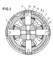
- Fig. 2 shows a cross section through the differential in the area of the differential pin 12 according to line II-II and a partial section at the level of the bayonet lock 5 according to line III-III.
- the differential housing is divided by the cylindrical fitting surface 8 between the cylindrical extension 6 of the drive part 3 and the cylindrical extension 7 of the end part 4.
- Shown for the differential with four differential bevel gears 13 is the mounting of the four differential bolts 12 in the central bolt receptacle 14 and the anti-rotation of the Bayonet lock 5 through the four differential bolts 12.
- the bayonet lock 5 can be seen in the locked state.
- the thread 23 is part of the two cylindrical lugs 6, 7 of the drive part 3 and the end part 4.
- the differential bolt 12 is only supported in the inner cylindrical lug 6, which here belongs to the drive part 3 .
- the outer cylindrical projection 7 from the end part 4 is pushed over the holes of the differential bolt and thus secures the differential bolt against slipping out.
- the assembly of the differential gear begins with the pre-assembly of the drive part.
- the driven bevel gear 17 is positioned in the drive part 3 .
- the axial position relative to the differential bolts 12 is fixed via the flat thrust washer 19 .
- the differential bevel gears 13 are inserted into the corresponding holes in the differential bolts 12 .
- the axial alignment of the differential bevel gears 13 on the differential pin 12 takes place via the spherical thrust washers 21.
- the pin receptacle 14 is fixed in its central position for the final assembly by means of a fixed assembly dome.
- the holes for the differential pin 12 must be aligned, ie drive part 3, differential bevel gears 13 and pin receptacle 14 must be aligned accordingly.
- the driven bevel gear 18 is measured relative to the mating surface 7 , aligned in the axial direction by means of the thrust washer 20 and then positioned in the end part 4 .
- the preassembled end part 4 is inserted into the preassembled drive part 3 and the bayonet lock 5 is locked against the drive part 3 by turning the end part 4 .
- the locked position must be selected so that the holes for the differential bolts 12 in the drive part 3 and in the end part 4 are aligned at the same time.
- all four differential bolts 12 are inserted into these bores and inserted into the bolt receptacle 14 through the end part 4, through the drive part 3 and through the differential bevel gears 13 .
- This end position is secured by the snap ring 15, which sits on each differential pin 12 and engages in a groove in the end part 4 .
- the differential bolts 12 serve both to support the differential angular gears 13 and to unlock the bayonet lock 5 .
- the differential is disassembled by pulling all the differential bolts 12 out of their installed position, which is secured with the snap rings 15 , from the differential gear housing.
- the differential pin 12 has the disassembly thread 16, where a suitable pulling tool can be attached. The rest of the disassembly is carried out in the reverse order of the assembly.
Landscapes
- Engineering & Computer Science (AREA)
- General Engineering & Computer Science (AREA)
- Mechanical Engineering (AREA)
- Retarders (AREA)
Claims (5)
- Différentiel à pignons coniques pour l'entraínement des essieux d'un véhicule à moteur, comprenant un boítier divisé, dans lequel sont disposés un boulon de différentiel (12), des pignons coniques de différentiel (13) montés sur le boulon de différentiel (12) et des pignons coniques de sortie (17, 18), qui entraínent les arbres d'essieux, le boítier se composant d'une partie d'entraínement (3) et d'une partie de fermeture (4), qui sont connectées par un ajustement cylindrique (8) et qui sont centrées sur les arbres d'essieux, et
la partie d'entraínement (3) et la partie de fermeture (4) présentant des prolongements cylindriques associés (6, 7), qui forment l'ajustement cylindrique (8) entre la partie d'entraínement (3) et la partie de fermeture (4), caractérisé en ce que les prolongements cylindriques (6, 7) se recouvrent axialement des deux côtés au-delà de la région dans laquelle est disposé le boulon de différentiel (12). - Différentiel selon la revendication 1, caractérisé en ce que la partie d'entraínement (3) est assemblée à la partie de fermeture (4) au moyen d'un joint à baïonnette (5).
- Différentiel selon la revendication 1, caractérisé en ce que la partie d'entraínement (3) est assemblée à la partie de fermeture (4) au moyen de l'ajustement cylindrique, qui est réalisé en tant qu'ajustement serré.
- Différentiel selon la revendication 1, 2 ou 3, caractérisé en ce que le boulon de différentiel (12) est monté dans la partie d'entraínement (3) et dans la partie de fermeture (4).
- Différentiel selon la revendication 1, 2 ou 3, caractérisé en ce que le boulon de différentiel (12) est monté seulement dans le prolongement cylindrique radialement interne (6, 7) de la partie d'entraínement (3) et de la partie de fermeture (4).
Priority Applications (2)
| Application Number | Priority Date | Filing Date | Title |
|---|---|---|---|
| DE59902050T DE59902050D1 (de) | 1999-08-20 | 1999-08-20 | Kegelrad-Ausgleichsgetriebe für Kraftfahrzeuge |
| EP19990116200 EP1079148B1 (fr) | 1999-08-20 | 1999-08-20 | Différentiel à pignons coniques pour véhicules automobiles |
Applications Claiming Priority (1)
| Application Number | Priority Date | Filing Date | Title |
|---|---|---|---|
| EP19990116200 EP1079148B1 (fr) | 1999-08-20 | 1999-08-20 | Différentiel à pignons coniques pour véhicules automobiles |
Publications (2)
| Publication Number | Publication Date |
|---|---|
| EP1079148A1 EP1079148A1 (fr) | 2001-02-28 |
| EP1079148B1 true EP1079148B1 (fr) | 2002-07-17 |
Family
ID=8238800
Family Applications (1)
| Application Number | Title | Priority Date | Filing Date |
|---|---|---|---|
| EP19990116200 Expired - Lifetime EP1079148B1 (fr) | 1999-08-20 | 1999-08-20 | Différentiel à pignons coniques pour véhicules automobiles |
Country Status (2)
| Country | Link |
|---|---|
| EP (1) | EP1079148B1 (fr) |
| DE (1) | DE59902050D1 (fr) |
Cited By (2)
| Publication number | Priority date | Publication date | Assignee | Title |
|---|---|---|---|---|
| DE102005024737A1 (de) * | 2005-05-31 | 2006-12-07 | Zf Friedrichshafen Ag | Ausgleichsgetriebe |
| DE102019204004A1 (de) * | 2019-03-25 | 2020-10-01 | Zf Friedrichshafen Ag | Differential |
Families Citing this family (5)
| Publication number | Priority date | Publication date | Assignee | Title |
|---|---|---|---|---|
| DE10107264A1 (de) * | 2001-02-16 | 2002-08-22 | Volkswagen Ag | Ausgleichsgetriebe mit einer Schmiervorrichtung |
| DE102004056087B4 (de) * | 2004-11-11 | 2007-04-12 | Getrag Getriebe- Und Zahnradfabrik Hermann Hagenmeyer Gmbh & Cie Kg | Differentialgetriebe |
| CN105960551B (zh) * | 2013-11-26 | 2019-02-12 | Gkn汽车有限公司 | 包括带有目标元件的联轴器总成的差速器 |
| US10113627B2 (en) * | 2017-02-02 | 2018-10-30 | American Axle & Manufacturing, Inc. | Differential assembly with multi-piece cross-pin |
| DE102018210944A1 (de) * | 2018-07-03 | 2020-01-09 | Audi Ag | Differentialgetriebe für ein Kraftfahrzeug, insbesondere für einen Kraftwagen, sowie Kraftfahrzeug |
Family Cites Families (5)
| Publication number | Priority date | Publication date | Assignee | Title |
|---|---|---|---|---|
| US1472629A (en) * | 1922-05-23 | 1923-10-30 | Charles C Boomsliter | Differential gear for automobiles |
| FR725834A (fr) * | 1931-11-05 | 1932-05-18 | Mode de construction du différentiel pour poids lourds | |
| DE2115593C2 (de) * | 1971-03-31 | 1981-11-19 | Klöckner-Humboldt-Deutz AG, 5000 Köln | Kegelräderausgleichsgetriebe für Kraftfahrzeuge |
| FR2382627A1 (fr) * | 1977-03-03 | 1978-09-29 | Chrysler France | Dispositif de transmission de couple dans un vehicule automobile, tel qu'un differentiel |
| DE9404408U1 (de) | 1993-04-19 | 1994-07-28 | Philips Electronics N.V., Eindhoven | Leuchte |
-
1999
- 1999-08-20 DE DE59902050T patent/DE59902050D1/de not_active Expired - Lifetime
- 1999-08-20 EP EP19990116200 patent/EP1079148B1/fr not_active Expired - Lifetime
Cited By (2)
| Publication number | Priority date | Publication date | Assignee | Title |
|---|---|---|---|---|
| DE102005024737A1 (de) * | 2005-05-31 | 2006-12-07 | Zf Friedrichshafen Ag | Ausgleichsgetriebe |
| DE102019204004A1 (de) * | 2019-03-25 | 2020-10-01 | Zf Friedrichshafen Ag | Differential |
Also Published As
| Publication number | Publication date |
|---|---|
| DE59902050D1 (de) | 2002-08-22 |
| EP1079148A1 (fr) | 2001-02-28 |
Similar Documents
| Publication | Publication Date | Title |
|---|---|---|
| DE10064815A1 (de) | Planetengetriebe | |
| EP2154367B1 (fr) | Procédé de montage d'un moyeu d'hélice sur un arbre de rotor d'une éolienne et éolienne | |
| EP0683333A1 (fr) | Différentiel pour l'entraînement de l'essieu d'un véhicule motorisé | |
| DE3629198A1 (de) | Ausgleichsgetriebe fuer ein kraftfahrzeug | |
| DE202012009415U1 (de) | Industriegetriebe | |
| WO2018059984A1 (fr) | Multiplicateur planétaire à rondelles de friction | |
| EP0816127B1 (fr) | Palier de roue d'un essieu moteur avec un corps d'essieu creux pour la charge des roues | |
| DE102015119173B4 (de) | Planetengetriebe sowie Verfahren zur Wartung eines Planetengetriebes | |
| WO2017046194A1 (fr) | Train planétaire destiné à une éolienne, muni de pignons satellites montés sur palier lisse | |
| WO2018059982A1 (fr) | Multiplicateur planétaire à rondelles de friction | |
| DE102004008538B4 (de) | Differential mit einer Bolzenbefestigungsbaugruppe | |
| EP1079148A1 (fr) | Différentiel à pignons coniques pour véhicules automobiles | |
| DE2913641A1 (de) | Lagerung der zahnstange einer zahnstangenlenkung fuer kraftfahrzeuge | |
| EP0958229B1 (fr) | Commande de cable a montage simplifie | |
| EP2347148B2 (fr) | Roue dentée et entraînement de tambour | |
| DE10333495A1 (de) | Verfahren für die Herstellung einer Radaufhängung zur Reduzierung der Spurungenauigkeit | |
| DE19631937B4 (de) | Ausgleichsgetriebe | |
| DE102016121393A1 (de) | Kugellager und Verfahren zu dessen Herstellung, Festlager, Lenkgetriebe und Lenksystem | |
| WO1990008272A1 (fr) | Raccord a bride resistant a la torsion | |
| EP1502799A1 (fr) | Entraínement de moyeu de roue | |
| DE10212671B4 (de) | Kegelradausgleichsgetriebe | |
| DE4003798C2 (fr) | ||
| DE102007017700A1 (de) | Verliersicherung für eine Nutmutter bei einer Welle-Nabe-Verbindung | |
| EP1502796A1 (fr) | Entraínement de moyeu de roue | |
| DE102019121688B4 (de) | Wellenlagerung, Getriebe sowie Verwendung eines Sicherungsrings |
Legal Events
| Date | Code | Title | Description |
|---|---|---|---|
| PUAI | Public reference made under article 153(3) epc to a published international application that has entered the european phase |
Free format text: ORIGINAL CODE: 0009012 |
|
| 17P | Request for examination filed |
Effective date: 20000219 |
|
| AK | Designated contracting states |
Kind code of ref document: A1 Designated state(s): DE FR GB |
|
| AX | Request for extension of the european patent |
Free format text: AL;LT;LV;MK;RO;SI |
|
| AKX | Designation fees paid |
Free format text: DE FR GB |
|
| 17Q | First examination report despatched |
Effective date: 20011009 |
|
| GRAG | Despatch of communication of intention to grant |
Free format text: ORIGINAL CODE: EPIDOS AGRA |
|
| GRAG | Despatch of communication of intention to grant |
Free format text: ORIGINAL CODE: EPIDOS AGRA |
|
| GRAH | Despatch of communication of intention to grant a patent |
Free format text: ORIGINAL CODE: EPIDOS IGRA |
|
| GRAH | Despatch of communication of intention to grant a patent |
Free format text: ORIGINAL CODE: EPIDOS IGRA |
|
| GRAA | (expected) grant |
Free format text: ORIGINAL CODE: 0009210 |
|
| AK | Designated contracting states |
Kind code of ref document: B1 Designated state(s): DE FR GB |
|
| REG | Reference to a national code |
Ref country code: GB Ref legal event code: FG4D Free format text: NOT ENGLISH |
|
| REF | Corresponds to: |
Ref document number: 59902050 Country of ref document: DE Date of ref document: 20020822 |
|
| GBT | Gb: translation of ep patent filed (gb section 77(6)(a)/1977) |
Effective date: 20020819 |
|
| ET | Fr: translation filed | ||
| PLBE | No opposition filed within time limit |
Free format text: ORIGINAL CODE: 0009261 |
|
| STAA | Information on the status of an ep patent application or granted ep patent |
Free format text: STATUS: NO OPPOSITION FILED WITHIN TIME LIMIT |
|
| 26N | No opposition filed |
Effective date: 20030422 |
|
| PGFP | Annual fee paid to national office [announced via postgrant information from national office to epo] |
Ref country code: FR Payment date: 20090806 Year of fee payment: 11 |
|
| PGFP | Annual fee paid to national office [announced via postgrant information from national office to epo] |
Ref country code: GB Payment date: 20090708 Year of fee payment: 11 Ref country code: DE Payment date: 20090831 Year of fee payment: 11 |
|
| GBPC | Gb: european patent ceased through non-payment of renewal fee |
Effective date: 20100820 |
|
| REG | Reference to a national code |
Ref country code: FR Ref legal event code: ST Effective date: 20110502 |
|
| REG | Reference to a national code |
Ref country code: DE Ref legal event code: R119 Ref document number: 59902050 Country of ref document: DE Effective date: 20110301 |
|
| PG25 | Lapsed in a contracting state [announced via postgrant information from national office to epo] |
Ref country code: DE Free format text: LAPSE BECAUSE OF NON-PAYMENT OF DUE FEES Effective date: 20110301 Ref country code: FR Free format text: LAPSE BECAUSE OF NON-PAYMENT OF DUE FEES Effective date: 20100831 |
|
| PG25 | Lapsed in a contracting state [announced via postgrant information from national office to epo] |
Ref country code: GB Free format text: LAPSE BECAUSE OF NON-PAYMENT OF DUE FEES Effective date: 20100820 |