EP1079156A1 - Joint mécanique sans contact - Google Patents
Joint mécanique sans contact Download PDFInfo
- Publication number
- EP1079156A1 EP1079156A1 EP00306996A EP00306996A EP1079156A1 EP 1079156 A1 EP1079156 A1 EP 1079156A1 EP 00306996 A EP00306996 A EP 00306996A EP 00306996 A EP00306996 A EP 00306996A EP 1079156 A1 EP1079156 A1 EP 1079156A1
- Authority
- EP
- European Patent Office
- Prior art keywords
- sealing
- sealing ring
- seal
- fluid
- ring
- Prior art date
- Legal status (The legal status is an assumption and is not a legal conclusion. Google has not performed a legal analysis and makes no representation as to the accuracy of the status listed.)
- Granted
Links
- 238000007789 sealing Methods 0.000 claims abstract description 172
- 239000012530 fluid Substances 0.000 claims abstract description 77
- 239000013013 elastic material Substances 0.000 claims description 5
- 229920003052 natural elastomer Polymers 0.000 claims description 3
- 229920001194 natural rubber Polymers 0.000 claims description 3
- 239000011148 porous material Substances 0.000 claims description 3
- 229920003051 synthetic elastomer Polymers 0.000 claims description 3
- 239000005061 synthetic rubber Substances 0.000 claims description 3
- 239000007789 gas Substances 0.000 description 68
- 230000003068 static effect Effects 0.000 description 27
- IJGRMHOSHXDMSA-UHFFFAOYSA-N Atomic nitrogen Chemical compound N#N IJGRMHOSHXDMSA-UHFFFAOYSA-N 0.000 description 5
- 206010067482 No adverse event Diseases 0.000 description 2
- 238000010276 construction Methods 0.000 description 2
- 230000007423 decrease Effects 0.000 description 2
- 239000002360 explosive Substances 0.000 description 2
- 230000014509 gene expression Effects 0.000 description 2
- 229910052757 nitrogen Inorganic materials 0.000 description 2
- 231100000614 poison Toxicity 0.000 description 2
- 230000007096 poisonous effect Effects 0.000 description 2
- 239000000126 substance Substances 0.000 description 2
- 238000011144 upstream manufacturing Methods 0.000 description 2
- 229920002449 FKM Polymers 0.000 description 1
- 244000043261 Hevea brasiliensis Species 0.000 description 1
- 230000002411 adverse Effects 0.000 description 1
- 229910001873 dinitrogen Inorganic materials 0.000 description 1
- 230000000694 effects Effects 0.000 description 1
- -1 inflammable gasses Substances 0.000 description 1
- 230000001105 regulatory effect Effects 0.000 description 1
- 238000000926 separation method Methods 0.000 description 1
- 230000001052 transient effect Effects 0.000 description 1
Images


Classifications
-
- F—MECHANICAL ENGINEERING; LIGHTING; HEATING; WEAPONS; BLASTING
- F16—ENGINEERING ELEMENTS AND UNITS; GENERAL MEASURES FOR PRODUCING AND MAINTAINING EFFECTIVE FUNCTIONING OF MACHINES OR INSTALLATIONS; THERMAL INSULATION IN GENERAL
- F16J—PISTONS; CYLINDERS; SEALINGS
- F16J15/00—Sealings
- F16J15/44—Free-space packings
-
- F—MECHANICAL ENGINEERING; LIGHTING; HEATING; WEAPONS; BLASTING
- F16—ENGINEERING ELEMENTS AND UNITS; GENERAL MEASURES FOR PRODUCING AND MAINTAINING EFFECTIVE FUNCTIONING OF MACHINES OR INSTALLATIONS; THERMAL INSULATION IN GENERAL
- F16J—PISTONS; CYLINDERS; SEALINGS
- F16J15/00—Sealings
- F16J15/16—Sealings between relatively-moving surfaces
- F16J15/34—Sealings between relatively-moving surfaces with slip-ring pressed against a more or less radial face on one member
- F16J15/3404—Sealings between relatively-moving surfaces with slip-ring pressed against a more or less radial face on one member and characterised by parts or details relating to lubrication, cooling or venting of the seal
- F16J15/3408—Sealings between relatively-moving surfaces with slip-ring pressed against a more or less radial face on one member and characterised by parts or details relating to lubrication, cooling or venting of the seal at least one ring having an uneven slipping surface
- F16J15/3412—Sealings between relatively-moving surfaces with slip-ring pressed against a more or less radial face on one member and characterised by parts or details relating to lubrication, cooling or venting of the seal at least one ring having an uneven slipping surface with cavities
- F16J15/342—Sealings between relatively-moving surfaces with slip-ring pressed against a more or less radial face on one member and characterised by parts or details relating to lubrication, cooling or venting of the seal at least one ring having an uneven slipping surface with cavities with means for feeding fluid directly to the face
-
- F—MECHANICAL ENGINEERING; LIGHTING; HEATING; WEAPONS; BLASTING
- F16—ENGINEERING ELEMENTS AND UNITS; GENERAL MEASURES FOR PRODUCING AND MAINTAINING EFFECTIVE FUNCTIONING OF MACHINES OR INSTALLATIONS; THERMAL INSULATION IN GENERAL
- F16J—PISTONS; CYLINDERS; SEALINGS
- F16J15/00—Sealings
- F16J15/16—Sealings between relatively-moving surfaces
- F16J15/34—Sealings between relatively-moving surfaces with slip-ring pressed against a more or less radial face on one member
- F16J15/3464—Mounting of the seal
- F16J15/3476—Means for minimising vibrations of the slip-ring
Definitions
- the present invention relates to a static pressure, non-contact type, mechanical seal suitable for use in rotary machines such, for example, as turbines, blowers, compressors, agitators, and rotary valves for handling a variety of gases including poisonous gases, inflammable gasses, explosive gases and powder-mixed gases.
- a known non-contact, mechanical seal comprises a stationary ring fixed on a seal case, a spring retainer provided on a rotary shaft, a rotary seal ring mounted on the rotary shaft to be movable in the axial direction and held between the stationary seal ring and the spring retainer, with O-rings placed as a secondary seal for sealing the space between the rotary shaft and the rotary seal ring, seal gas supply passages that pass through the stationary seal ring and supply a gas - under a higher pressure than the fluid to be sealed - between opposed seal end faces of the two seal rings, and spring members, placed between the rotary seal ring and the spring retainer, pressing the rotary seal ring against the stationary seal ring, wherein the two seal rings are relatively rotated with the opposed seal end faces held in a non-contacting state by the seal gas supplied therebetween, thereby producing a seal between the inner and outer circumferential regions of the relatively rotating parts, that is, the sealed fluid region and the outside region (usually, the atmospheric region).
- a static pressure fluid film of the seal gas is formed between the two seal end faces, and the presence of this fluid film holds the two seal rings in a non-contacting state, that is, keeps the two seal rings only slightly spaced from each other.
- the seal gas supplied between the two seal end faces is under a higher pressure than the fluid to be sealed. Therefore, the seal gas leaks out to the sealed fluid region and the outside region, but the sealed fluid cannot enter between the two seal end faces. Thus, the sealed fluid is sealed and prevented from leaking out to the outside region.
- the shaft can thus be sealed in a rotary machine handling such fluids as poisonous gases, inflammable gases and explosive gases that must not leak out.
- a non-contact mechanical seal for making a substantially fluid-tight seal around a rotatory shaft; said seal comprising a seal case; a rotatory shaft that extends through said seal case and is adapted for rotation in relation thereto; a first stationary sealing ring having a first sealing face, which first sealing ring is fixedly secured within said seal case around said shaft; spring retaining means fixedly secured to said shaft; a second rotatory sealing ring having a second sealing face that opposes said first sealing face, which second sealing ring is mounted over said shaft between the first stationary seal ring and said spring retaining means; connecting means for connecting said second sealing ring to said shaft for rotation therewith whilst allowing said second sealing ring to move axially with respect to said shaft; spring means between said spring retaining means and said second sealing ring for urging the second sealing face towards said first sealing face; secondary sealing means for sealing between the second sealing ring and said shaft; and means for admitting a sealing fluid between said first and second
- Said sealing fluid may be selected according to the required sealing conditions.
- the sealing fluid should be harmless, even if it leaks into the region to be sealed or out of the seal, and should have no adverse effects on the fluid to be sealed.
- Said sealing fluid is preferably a gas and, generally, clean nitrogen may be used; clean nitrogen is inert to a variety of substances and harmless to humans.
- Said means for admitting pressurised sealing fluid into the annular space may comprise means for conducting sealing fluid from said space between the first and second sealing faces to the annular space.
- Said second sealing ring may be provided with a plurality of fluid-conducting passages, each of which extends between a first open end that opens onto the second sealing face and a second open end that opens into the annular space.
- Said means for admitting sealing fluid between said first and second sealing faces may comprise a plenum between said seal case and said first sealing ring, means for supplying sealing fluid through the seal case to the plenum, and means for conducting said fluid through the first ring, from the plenum to a plurality of spaced openings formed in said first sealing face.
- Said plenum may be formed by a circumferential groove formed in an outer surface of the first stationary sealing ring, which outer surface is contiguous an inner surface of the seal cone to close said plenum.
- Said first stationary sealing ring may be clamped onto the seal case.
- Said means for conducting fluid through the first sealing ring may comprise one or more branched passageways that extend from the plenum to one or more of said openings in said first sealing face.
- Said first sealing face may comprise one or more pressure-generating grooves.
- the or each groove may be circular or arc-shaped and may be formed substantially concentrically with the first sealing face.
- a plurality of arc-shaped, substantially concentric, pressure-generating grooves may be provided, which grooves all have substantially the same radius and are arranged end-to-end in a discontinuous, annular configuration.
- the distance between adjacent grooves in the circumferential direction may be substantially the same as the width of each groove in the radial direction.
- Each of said arc-shaped recessed grooves may have the identical groove width and depth.
- said means for conducting sealing fluid through the first sealing ring communicate with each of said grooves.
- each fluid-conducting passage of the second sealing ring is preferably aligned with the or each pressure-generating groove in the first sealing face.
- Said one open end of each passageway may be circular or non-circular, but advantageously has a width in the radial direction of the second sealing face that is substantially the same or smaller than the width of the or each pressure-generating groove in the first sealing face.
- the pressure of the sealing gas between the first and second sealing faces is about 1.5 bar higher than the pressure of the fluid to be sealed.
- Said plenum may be connected to said means for conducting sealing fluid through the first sealing ring by constriction means such, for example, as an orifice, capillary or porous material having a reduced diameter.
- Said constriction means serve to prevent or hinder the back-flow of sealing fluid into the plenum in the event that the pressure of sealing fluid between the opposing sealing faces increases, for instance owing to a transient closing of the gap between the two sealing faces.
- said sealing fluid may be admitted to the plenum at a pressure of about 1.0 to 3.0 bar greater than the pressure of the fluid to be sealed, such that the pressure between the sealing faces is 0.5 to 1.5 bar greater than the pressure of the fluid to be sealed.
- Said elastic sealing ring members may be formed form a non-compressible, substantially isovolumetric, elastic material.
- said elastic material may be selected from natural or synthetic rubbers.
- each sealing ring member expands slightly in the radial direction, that is substantially transverse to the longitudinal axis of the shaft, to hold the second sealing ring firmly within the sleeve member.
- each of said elastic sealing ring members may comprise an O-ring.
- Each of said O-rings may be accommodated in a respective circumferential groove formed in the outer surface of the second rotatory sealing ring.
- Said sleeve member may comprise a hollow cylinder that is fixedly secured to or formed integrally with the spring retaining means.
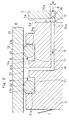
- a non-contact-type mechanical seal embodying the present invention comprises a stationary seal ring 3 clamped on a seal case 2, a spring retainer 5 fitted over and fixed on a rotary shaft 4 of a rotary machine, a rotary seal ring 6 fitted over and held on the rotary shaft 4 in a state movable in the axial direction (front-to-backward direction), spring members 7 that press the rotary seal ring 6 against the stationary seal ring 3, a seal gas supply system 9 to supply seal gas 8 between seal end faces 3a, 6a, that is, the opposed seal end faces of the two seal rings 3, 6, and a vibration preventing device 10 for preventing the vibration of the rotary seal ring 6, wherein the seal end faces 3a, 6a are relatively rotated in a non-contacting state, thereby producing a seal between the inner circumferential region of the relatively rotating parts, that is, the sealed fluid region G, and the outer circumferential region, that is the outside region A.
- the sealed fluid region G communicates with
- the seal case 2 is substantially cylindrical in shape, with the rear end mounted on the rotary machine housing (not shown) in such a way that the rotary shaft 4 coaxially passes therethrough.
- the stationary seal ring 3 is a ring-shaped body, and concentrically and loosely surrounds the rotary shaft 4 and is fitted into and fixed in an inner circumferential portion of the seal case 2 as shown in FIG.1.
- the seal end face 3a, or the front end of the stationary seal ring 3, (hereinafter referred to as stationary seal end face) is an annular, smooth surface and is substantially perpendicular to the axial line.
- a labyrinthine seal 11 is provided between the rear end portion of the stationary seal ring 3 and the rotary shaft 4.
- the labyrinthine seal 11 comprises a plurality of axially spaced annular protrusions 11a provided side-by-side on the inner circumferential surface of the stationary seal ring 3, the protrusions 11a extending close to the outer circumferential surface of the rotary shaft 4 as shown in FIG.1.
- the spring retainer 5 is a ring-shaped body which is provided in front of the stationary seal ring 3 and fitted and fixed around the rotary shaft 4 as shown in FIG.1.
- annular O-ring abutment 12 In the inner and outer circumferential portions of the spring retainer 5, there are concentrically and respectively provided an annular O-ring abutment 12 and a cylindrical holder portion 13 that extends rearwards.
- the rotary seal ring 6 is a ring-formed body with a rear end face 6a (hereafter referred to as rotary seal end face) formed into an annular smooth surface, substantially perpendicular to the axial line as shown in FIG.1.
- rotary seal end face a rear end face 6a (hereafter referred to as rotary seal end face) formed into an annular smooth surface, substantially perpendicular to the axial line as shown in FIG.1.
- the rotary seal ring 6 is fitted over and held on the rotary shaft 4 in a state movable in the axial direction with an O-ring 14 placed between the inner circumferential surface of the rotary seal ring 6 and the outer circumferential surface of the rotary shaft 4.
- the rotation stopper pin 150 is screwed into the front end of the rotary seal ring 6.
- the spring members 7 include a plurality of springs (only one spring is shown) placed between the spring retainer 5 and the rotary seal ring 6 as shown in FIG.1 and thrust the rotary seal ring 6 toward the stationary seal ring 3, generating a closing force that works to close the gap between the seal end faces 3a, 6a.
- the seal gas supply system 9 comprises a series of seal gas supply passages 15, 16, 17, 18 formed in the seal case 2 and the stationary seal ring 3 and a squeezer 19 as shown in FIG.1 to FIG.3.
- the seal gas 8 under a higher pressure than the pressure Pg of the sealed fluid is supplied between the seal end faces 3a, 6a to produce a static pressure (opening force) that works to open the seal end faces 3a, 6a.
- the seal gas supply passages include static pressure-generating grooves 15 formed on the stationary seal end face 3a, an annular communicating space 16 formed between an outer circumferential surface of the stationary seal ring 3 and an inner circumferential surface of the seal case 2 and a seal gas supply passage 18 on the seal ring side extending from the communicating space 16 to the static pressure-generating grooves 15 through the stationary seal ring 3.
- the static pressure-generating grooves 15 are a number of shallow, recessed grooves or a shallow, recessed, continuous groove formed concentrically with the stationary seal end face 3a in an annular form. In this example, separate grooves are formed. That is, the static pressure-generating grooves 15 are a plurality of arc-shaped recessed grooves 15a formed and disposed end-to-end in an annular form concentrically with the stationary seal end face 3a as shown in FIG.3. All the arc-shaped recessed grooves 15a are identical in groove width W and groove depth. More particularly, four arc-shaped recessed grooves 15a, all identical in shape, are formed on the stationary seal end face 3a at the same interval L.
- the length L in the circumferential direction between the adjacent arc-shaped recessed grooves 15a on the stationary seal end face portion 15b (hereinafter referred to as "inter-groove land portion") is set at the same or about the same as the groove width W of the static pressure-generating grooves 15.
- the communicating space 16 is sealed with O-rings 20 placed between the opposed circumferential surfaces of the seal case 2 and the stationary seal ring 3.
- the downstream end of the seal gas supply passage 18 branches out to the respective openings 18a of the arc-shaped recessed grooves 15a forming the static pressure-generating grooves 15.
- the upstream end of the seal gas supply passage 17 is connected to a seal gas source (not shown) from which the seal gas 8 is supplied to the static pressure-generating grooves 15 through the passage 17 on the seal case side, the communicating space 16 and the passage 18 on the seal ring side.
- the seal gas 8 is selected according to sealing conditions. That is, the gas to selected should be harmless, even if the gas leaks out to the regions G, A and should have no adverse effects on the gas in the machine, that is, the sealed fluid.
- clean nitrogen gas is used that is inert to a variety of substances and harmless to humans.
- the seal gas 8 is supplied only when the rotary machine is in operation (while the rotary shaft 4 is rotating), and the supply of the seal gas 8 is suspended when the machine is put out of operation. The rotary machine is started only after the seal gas 8 is supplied and the seal end faces 3a, 6a are held properly in a non-contact state. And the supply of the seal gas 8 is cut-off only after the rotary machine is put out of operation with the rotary shaft coming to a complete stop.
- the squeezers 19 suitable for the purpose include orifices, capillary tubes and porous materials that have a squeezing function.
- the squeezer 19 is provided at a suitable point in the seal gas supply passage 18 - on the upstream side of the passage branching portion where the passage is branched out to communicate with the arc-shaped recessed grooves 15a.
- the seal gas 8 led into the static pressure-generating grooves 15 produces an opening force to open the seal end faces 3a, 6a.
- This opening force is produced by a static pressure generated by the seal gas 8 led between the seal end faces 3a, 6a. Therefore, the seal end faces 3a, 6a are held in a non-contact state as an equilibrium is established between the opening force and the closing force (spring load) by the spring members 7 that work to close the gap between the seal end faces 3a, 6a.
- the seal gas 8 led into the static pressure-generating grooves 15 forms a static pressure fluid film between the seal end faces 3a, 6a.
- this fluid film produces a seal between the regions inside and outside the seal end face 3a, 6a, that is, the sealed fluid region G, and the outside region A.
- the pressure of the seal gas 8 and the spring force (spring load) of the spring members 7 are properly adjusted so that the gap between the seal end faces 3a, 6a is correct - generally 5 to 15 ⁇ m.
- the seal gas 8 is squeezed by the squeezer 19 before being led into the static pressure-generating grooves 15. Therefore, even if the gap between the seal end faces 3a, 6a changes, the gap will automatically be adjusted to the correct size.
- the gap between the seal end faces 3a, 6a decreases, the pressure in the static pressure generating grooves 15 is increased by the squeezing function of the same squeezer 19 as mentioned above, and the opening force outdoes the closing force. As a result, the gap between the seal end faces 3a, 6a increases to restore the gap to a proper level.
- seal gas pressure the pressure Ps (hereinafter referred to as "seal gas pressure") of the seal gas 8 supplied to the passage 17 on the seal case side from the seal gas supply source is controlled so that the pressure Pp in the respective arc-shaped recessed grooves 15a (hereinafter referred to as “pocket pressure") of the seal gas 8 led in the static pressure-generating grooves 15 from the seal gas supply passage 18 through the squeezer 19 is 0.5 to 1.5 bar higher than the sealed fluid pressure Pg.
- the length L in the circumferential direction of the inter-groove land portion 15b between adjacent grooves on the stationary seal end face 3a is set at the same or about the same as the groove width W (groove width of the arc-shaped recessed grooves 15a) of the static pressure-generating grooves 15 as mentioned above. If Pp ⁇ Pg + 0.5 bar, then the pressure distribution of the fluid film formed by the seal gas 8 between the seal end faces 3a, 6a changes greatly in the area corresponding to the inter-groove land portion 15b.
- the seal gas pressure Ps is set 1 to 3 bar higher than the sealed fluid pressure Pg (Pg + 1 bar ⁇ Ps ⁇ Pg + 3 bar) so that the pocket pressure Pp is maintained at Pg +0.5 bar ⁇ Pp ⁇ Pg +1.5 bar.
- the seal gas pressure Ps is kept constant such that Pg + 0.5 bar ⁇ Pp ⁇ Pg +1.5 bar and Pg + 1 bar ⁇ Ps ⁇ Pg + 3 bar.
- the seal gas pressure Ps is kept constant.
- the adjustment and control of the seal gas pressure Ps may be effected according to fluctuations in the sealed fluid pressure Pg.
- the aforesaid pressures Pg, Pp, Ps are gauge pressures (bar) in relation to the atmosphere.
- the vibration-preventing device 10 comprises, as shown in FIG.1 and FIG.2, the holder portion 13 of the spring retainer 5 that surrounds the outer circumferential portion of the rotary seal ring 6, a pair of O-ring grooves 21 formed in an outer circumferential portion of the rotary seal ring 6, a pair of O-rings 22 engaged in the O-ring grooves 21 and slightly spaced from each other in the axial direction, an annular space 23 formed between the opposed circumferential surfaces of the rotary seal ring 6 and the holder portion 13 of the spring retainer 5 and sealed by the O-rings 22.
- the O-rings 22 are formed of a non-compressive, elastic material like synthetic rubber and natural rubber.
- the O-rings 22 are properly pressed between the O-ring groove bottoms 21a of the O-ring grooves 21 and an inner circumferential surface 13a of the holder portion 13 (to the extent that the rotary seal ring 6 is not prevented from moving in the axial direction), and the annular space 23 is sealed on the two end portions in the axial direction.
- said O-rings 22, the other O-ring 14, and said O-ring 20 may be made of Viton®.
- Respective seal gas leading passages 24 pass through the rotary seal ring 6 as shown in FIG.1 and FIG.2, each having one end 24a opening into the seal end face 6a and another end 24b opening into the annular space 23.
- the one open ends 24a of the respective seal gas leading passages 24 are circular and positioned exactly opposite to the static pressure-generating grooves 15 as shown in FIG.2 and FIG.4.
- the diameter D (to be exact, the length in the radial direction of the rotary seal ring 6) is set at the same as or slightly smaller than the groove width W (width W of the arc-shaped recessed groove 15a) of the static pressure-generating grooves 15, that is D ⁇ W.
- the other open ends 24b of the respective seal gas leading passages 24 are situated between the O-ring grooves 21, that is, between the O-rings 22.
- the same number of seal gas leading passages 24 as the arc-shaped recessed grooves 15a, that is, four passages 24, are provided at the same interval in the circumferential direction of the rotary seal ring 6.
- those ends 24a and 24b open onto the seal end face 6a and on the outer circumferential surface of the rotary seal ring 6 at positions at the same interval in the circumferential direction of the rotary seal ring 6.
- the gap between the seal end faces 3a and 6a is kept in the correct non-contacting state by the seal gas 8 supplied to the static pressure-generating grooves 15, and at the same time the annular space 23 is maintained at the same pressure as that between the stationary seal end faces 3a, 6a by leading the seal gas 8 into the annular space 23 through the seal gas leading passages 24. Therefore, the respective O-rings 22 are pressed against inner transverse walls 21b in the annular space 23 by the seal gas 8 and compressed in the axial direction of the rotary seal end face 6a.
- the respective O-rings 22 are made of a non-compressive (isovolumetric) elastic material, and that increases the pressing force of the respective O-rings 22 against the outer circumferential surface (the bottoms 21a of the O-ring grooves 21) of the rotary seal ring 6 and the opposite inner circumferential surface 13a of the holder portion 13 of the spring retainer 5. As a result, the rotary seal ring 6 is firmly held on the inner circumferential surface of the holder portion 13 of the spring retainer 5 by O-rings 22.
- the present invention can be suitably applied to a non-contact-type, mechanical seal of such a construction that the outer circumferential area of the relatively rotating parts of the stationary seal end faces 3a, 6a is the region for sealed fluid, while the inner circumferential area is the atmospheric region.
Landscapes
- Engineering & Computer Science (AREA)
- General Engineering & Computer Science (AREA)
- Mechanical Engineering (AREA)
- Mechanical Sealing (AREA)
Applications Claiming Priority (2)
| Application Number | Priority Date | Filing Date | Title |
|---|---|---|---|
| JP22960199 | 1999-08-16 | ||
| JP22960199A JP3354524B2 (ja) | 1999-08-16 | 1999-08-16 | 非接触形メカニカルシール |
Publications (2)
| Publication Number | Publication Date |
|---|---|
| EP1079156A1 true EP1079156A1 (fr) | 2001-02-28 |
| EP1079156B1 EP1079156B1 (fr) | 2009-05-13 |
Family
ID=16894746
Family Applications (1)
| Application Number | Title | Priority Date | Filing Date |
|---|---|---|---|
| EP00306996A Expired - Lifetime EP1079156B1 (fr) | 1999-08-16 | 2000-08-16 | Joint mécanique sans contact |
Country Status (5)
| Country | Link |
|---|---|
| US (1) | US6431551B1 (fr) |
| EP (1) | EP1079156B1 (fr) |
| JP (1) | JP3354524B2 (fr) |
| KR (1) | KR100369928B1 (fr) |
| DE (1) | DE60042188D1 (fr) |
Cited By (6)
| Publication number | Priority date | Publication date | Assignee | Title |
|---|---|---|---|---|
| EP2362122A3 (fr) * | 2010-02-24 | 2011-10-12 | KSB Aktiengesellschaft | Bague d'étanchéité glissante et procédé d'optimisation de leur comportement en fonctionnement |
| CN109780348A (zh) * | 2019-03-16 | 2019-05-21 | 安庆泽远化工有限公司 | 一种防泄漏化工管道法兰 |
| CN109899610A (zh) * | 2019-03-16 | 2019-06-18 | 安庆泽远化工有限公司 | 一种防泄漏化工管道法兰的制造工艺 |
| EP3514415B1 (fr) * | 2012-12-07 | 2021-05-26 | A.W. Chesterton Company | Joint mécanique fendu à alignement automatique employant un ensemble de polarisation axiale à engagement sélectif |
| EP4411180A1 (fr) * | 2023-02-03 | 2024-08-07 | Hamilton Sundstrand Corporation | Ensembles d'étanchéité pour l'étanchéité entre des composants rotatifs et non rotatifs |
| WO2025021345A1 (fr) * | 2023-07-27 | 2025-01-30 | Eagleburgmann Germany Gmbh & Co. Kg | Agencement d'étanchéité à bague collectrice lubrifiée au gaz |
Families Citing this family (27)
| Publication number | Priority date | Publication date | Assignee | Title |
|---|---|---|---|---|
| US6550779B2 (en) * | 1999-07-27 | 2003-04-22 | Northeast Equipment, Inc. | Mechanical split seal |
| GB2375148A (en) * | 2001-04-30 | 2002-11-06 | Corac Group Plc | A dry gas seal |
| GB0202468D0 (en) * | 2002-02-02 | 2002-03-20 | Crane John Uk Ltd | Seals |
| JP3839432B2 (ja) * | 2003-10-30 | 2006-11-01 | 株式会社神鋼環境ソリューション | コンタミレスの耐食性軸封装置 |
| FR2869671B1 (fr) * | 2004-04-29 | 2006-06-02 | Snecma Moteurs Sa | Dispositif de lubrification d'un composant dans un ensemble de pieces |
| JP4336286B2 (ja) * | 2004-10-08 | 2009-09-30 | 日本ピラー工業株式会社 | 静圧形ノンコンタクトガスシール |
| US7744094B2 (en) * | 2004-11-09 | 2010-06-29 | Eagle Industry Co., Ltd. | Mechanical seal device |
| CN1312421C (zh) * | 2005-01-18 | 2007-04-25 | 哈尔滨工业大学 | 开度无级调节的非接触式气体换向阀 |
| US7305963B2 (en) * | 2005-05-13 | 2007-12-11 | Juan Zak | Blade-thru-slot combustion engine, compressor, pump and motor |
| US7380841B2 (en) * | 2005-10-26 | 2008-06-03 | Hall David R | High pressure connection |
| ITMC20070238A1 (it) * | 2007-12-12 | 2009-06-13 | Meccanotecnica Umbra Spa | Tenuta meccanica frontale per pompe, ad anelli striscianti con lubrificazione a fluido, di tipo perfezionata. |
| GB0800509D0 (en) * | 2008-01-11 | 2008-02-20 | Crane John Uk Ltd | Seals |
| JP5519346B2 (ja) * | 2010-03-16 | 2014-06-11 | 日本ピラー工業株式会社 | ドライコンタクトメカニカルシール |
| JP5617532B2 (ja) | 2010-10-29 | 2014-11-05 | ソニー株式会社 | 誘電サイトメトリ装置及び誘電サイトメトリによる細胞分取方法 |
| CN102518803A (zh) * | 2011-12-29 | 2012-06-27 | 大连华阳光大密封有限公司 | 一种补偿环辅助密封结构 |
| US8740224B2 (en) * | 2012-02-28 | 2014-06-03 | General Electric Company | Seal assembly for a turbomachine |
| CN103644302B (zh) * | 2013-12-24 | 2016-07-06 | 四川日机密封件股份有限公司 | 可随压力自适应变形的机械密封装置 |
| DE102013227208A1 (de) * | 2013-12-30 | 2015-07-02 | Siemens Aktiengesellschaft | Dichtsystem für eine Dampfturbine sowie Dampfturbine |
| CN105202197A (zh) * | 2015-10-16 | 2015-12-30 | 长安大学 | 一种振动搅拌机的气密封结构及其气密封方法 |
| WO2017214542A1 (fr) | 2016-06-10 | 2017-12-14 | John Crane Uk Ltd. | Garniture d'étanchéité aux gaz sèche munie d'une soupape d'arrêt commandée électroniquement |
| GB2553565B (en) * | 2016-09-09 | 2019-04-10 | Rolls Royce Plc | Air riding seal arrangement |
| WO2018213313A1 (fr) | 2017-05-15 | 2018-11-22 | John Crane Uk Ltd. | Joint d'étanchéité à gaz sec muni d'une charge de support commandée électroniquement |
| CN108302204B (zh) * | 2018-02-27 | 2024-06-04 | 清华大学 | 可调型机械密封装置 |
| DE102020127710A1 (de) * | 2020-10-21 | 2022-04-21 | Rolls-Royce Deutschland Ltd & Co Kg | Vorrichtung mit wenigstens zwei Bauteilen und Gasturbinentriebwerk mit einer solchen Vorrichtung |
| CN113118796B (zh) * | 2021-03-09 | 2022-07-26 | 广州市昊志机电股份有限公司 | 一种外转内冷刀柄 |
| CN114739563B (zh) * | 2022-04-14 | 2023-11-28 | 浙江工业大学 | 一种静环可移动的机械密封径向膜压分布测试装置 |
| CN116146604B (zh) * | 2023-02-15 | 2026-04-10 | 广东优社动力科技有限公司 | 一种静压轴承 |
Citations (11)
| Publication number | Priority date | Publication date | Assignee | Title |
|---|---|---|---|---|
| DE3925404A1 (de) * | 1989-07-12 | 1991-01-24 | Escher Wyss Gmbh | Trockengasdichtung mit ruecklaufentlastung |
| EP0438346A1 (fr) * | 1990-01-17 | 1991-07-24 | EG&G SEALOL, INC. | Joint amélioré en spirale et rainure lubrifié à gaz |
| EP0466076A2 (fr) * | 1990-07-09 | 1992-01-15 | Ebara Corporation | Garniture à bague glissante avec rainures hélicoidales |
| EP0597148A1 (fr) * | 1992-11-12 | 1994-05-18 | Nippon Pillar Packing Co. Ltd. | Dispositif d'étanchéité de type sans-contact |
| EP0601821A1 (fr) * | 1992-12-11 | 1994-06-15 | Nippon Pillar Packing Co., Ltd. | Joint d'axe sans contact |
| US5421593A (en) * | 1993-08-05 | 1995-06-06 | Nippon Pillar Packing Co., Ltd. | Shaft seal device |
| EP0684413A1 (fr) * | 1994-03-22 | 1995-11-29 | Nippon Pillar Packing Co. Ltd. | Dispositif de joint d'arbre sans contact |
| JPH094720A (ja) * | 1995-06-19 | 1997-01-07 | Nippon Pillar Packing Co Ltd | 軸封装置 |
| JPH09196184A (ja) * | 1996-01-24 | 1997-07-29 | Nippon Pillar Packing Co Ltd | ポンプ用軸封装置 |
| US5722665A (en) * | 1992-02-26 | 1998-03-03 | Durametallic Corporation | Spiral groove face seal |
| WO1999031412A1 (fr) | 1997-12-17 | 1999-06-24 | A.W. Chesterton Company | Systeme de regulation de la pression en retour de fluides pour un joint d'etancheite mecanique |
Family Cites Families (9)
| Publication number | Priority date | Publication date | Assignee | Title |
|---|---|---|---|---|
| US2531079A (en) * | 1948-02-18 | 1950-11-21 | Crane Packing Co | Cooled and lubricated rotary seal |
| US3589738A (en) * | 1969-06-13 | 1971-06-29 | Borg Warner | Mechanical seal for pulp pumps |
| US3727924A (en) * | 1970-07-08 | 1973-04-17 | Champlain Power Prod Ltd | Externally pressurized seal |
| SU406481A1 (fr) * | 1971-07-30 | 1974-12-05 | ||
| DE3223703C2 (de) * | 1982-06-25 | 1984-05-30 | M.A.N. Maschinenfabrik Augsburg-Nürnberg AG, 4200 Oberhausen | Gasgesperrte Wellendichtung mit radialem Dichtspalt |
| GB9121683D0 (en) * | 1991-10-12 | 1991-11-27 | Aes Eng Ltd | Spring retainer |
| JP3192152B2 (ja) * | 1997-11-21 | 2001-07-23 | 日本ピラー工業株式会社 | 静圧形ノンコクタクトガスシール |
| US6076830A (en) * | 1997-12-17 | 2000-06-20 | A.W. Chesterton Company | Dual non-contacting mechanical face seal having concentric seal faces |
| US6059293A (en) * | 1997-12-17 | 2000-05-09 | A.W. Chesterton Company | Split mechanical face seal with seal face fluid introducing structure |
-
1999
- 1999-08-16 JP JP22960199A patent/JP3354524B2/ja not_active Expired - Lifetime
-
2000
- 2000-08-14 KR KR10-2000-0046927A patent/KR100369928B1/ko not_active Expired - Fee Related
- 2000-08-15 US US09/638,897 patent/US6431551B1/en not_active Expired - Lifetime
- 2000-08-16 EP EP00306996A patent/EP1079156B1/fr not_active Expired - Lifetime
- 2000-08-16 DE DE60042188T patent/DE60042188D1/de not_active Expired - Lifetime
Patent Citations (11)
| Publication number | Priority date | Publication date | Assignee | Title |
|---|---|---|---|---|
| DE3925404A1 (de) * | 1989-07-12 | 1991-01-24 | Escher Wyss Gmbh | Trockengasdichtung mit ruecklaufentlastung |
| EP0438346A1 (fr) * | 1990-01-17 | 1991-07-24 | EG&G SEALOL, INC. | Joint amélioré en spirale et rainure lubrifié à gaz |
| EP0466076A2 (fr) * | 1990-07-09 | 1992-01-15 | Ebara Corporation | Garniture à bague glissante avec rainures hélicoidales |
| US5722665A (en) * | 1992-02-26 | 1998-03-03 | Durametallic Corporation | Spiral groove face seal |
| EP0597148A1 (fr) * | 1992-11-12 | 1994-05-18 | Nippon Pillar Packing Co. Ltd. | Dispositif d'étanchéité de type sans-contact |
| EP0601821A1 (fr) * | 1992-12-11 | 1994-06-15 | Nippon Pillar Packing Co., Ltd. | Joint d'axe sans contact |
| US5421593A (en) * | 1993-08-05 | 1995-06-06 | Nippon Pillar Packing Co., Ltd. | Shaft seal device |
| EP0684413A1 (fr) * | 1994-03-22 | 1995-11-29 | Nippon Pillar Packing Co. Ltd. | Dispositif de joint d'arbre sans contact |
| JPH094720A (ja) * | 1995-06-19 | 1997-01-07 | Nippon Pillar Packing Co Ltd | 軸封装置 |
| JPH09196184A (ja) * | 1996-01-24 | 1997-07-29 | Nippon Pillar Packing Co Ltd | ポンプ用軸封装置 |
| WO1999031412A1 (fr) | 1997-12-17 | 1999-06-24 | A.W. Chesterton Company | Systeme de regulation de la pression en retour de fluides pour un joint d'etancheite mecanique |
Non-Patent Citations (2)
| Title |
|---|
| PATENT ABSTRACTS OF JAPAN vol. 1997, no. 05 30 May 1997 (1997-05-30) * |
| PATENT ABSTRACTS OF JAPAN vol. 1997, no. 11 28 November 1997 (1997-11-28) * |
Cited By (10)
| Publication number | Priority date | Publication date | Assignee | Title |
|---|---|---|---|---|
| EP2362122A3 (fr) * | 2010-02-24 | 2011-10-12 | KSB Aktiengesellschaft | Bague d'étanchéité glissante et procédé d'optimisation de leur comportement en fonctionnement |
| EP2515013A1 (fr) | 2010-02-24 | 2012-10-24 | KSB Aktiengesellschaft | Bague dýétanchéité glissante |
| EP3514415B1 (fr) * | 2012-12-07 | 2021-05-26 | A.W. Chesterton Company | Joint mécanique fendu à alignement automatique employant un ensemble de polarisation axiale à engagement sélectif |
| CN109780348A (zh) * | 2019-03-16 | 2019-05-21 | 安庆泽远化工有限公司 | 一种防泄漏化工管道法兰 |
| CN109899610A (zh) * | 2019-03-16 | 2019-06-18 | 安庆泽远化工有限公司 | 一种防泄漏化工管道法兰的制造工艺 |
| CN109780348B (zh) * | 2019-03-16 | 2020-10-09 | 苏州乐赢科技咨询有限公司 | 一种防泄漏化工管道法兰 |
| CN109899610B (zh) * | 2019-03-16 | 2020-12-22 | 安徽松之梦科技有限公司 | 一种防泄漏化工管道法兰的制造工艺 |
| EP4411180A1 (fr) * | 2023-02-03 | 2024-08-07 | Hamilton Sundstrand Corporation | Ensembles d'étanchéité pour l'étanchéité entre des composants rotatifs et non rotatifs |
| US12117083B2 (en) | 2023-02-03 | 2024-10-15 | Hamilton Sundstrand Corporation | Sealing assemblies for sealing between rotating and non-rotating components |
| WO2025021345A1 (fr) * | 2023-07-27 | 2025-01-30 | Eagleburgmann Germany Gmbh & Co. Kg | Agencement d'étanchéité à bague collectrice lubrifiée au gaz |
Also Published As
| Publication number | Publication date |
|---|---|
| EP1079156B1 (fr) | 2009-05-13 |
| DE60042188D1 (de) | 2009-06-25 |
| US6431551B1 (en) | 2002-08-13 |
| JP3354524B2 (ja) | 2002-12-09 |
| KR20010050076A (ko) | 2001-06-15 |
| KR100369928B1 (ko) | 2003-01-29 |
| JP2001056058A (ja) | 2001-02-27 |
Similar Documents
| Publication | Publication Date | Title |
|---|---|---|
| EP1079156B1 (fr) | Joint mécanique sans contact | |
| US6135458A (en) | Static pressure non-contact gas seal | |
| JPWO1999027281A1 (ja) | 静圧形ノンコンタクトガスシール | |
| JP3086280B2 (ja) | ロッドシール | |
| US4932432A (en) | Shutoff and flow-control valve | |
| ES2003141A6 (es) | Rotula para transferir fluidos a elevada presion. | |
| US6161834A (en) | Pressure energized seal | |
| US4187871A (en) | Pressure-biased shuttle valve | |
| KR960704186A (ko) | 스위블용 밀봉장치(sealing arrangement for a swivel) | |
| JPS6487975A (en) | Sealing device for pump | |
| US3531146A (en) | Press or shrink fit joints | |
| US5192083A (en) | Single ring sector seal | |
| US4506692A (en) | Device for feeding a pressure medium into a shaft | |
| JPH0143186B2 (fr) | ||
| JP4315394B2 (ja) | メカニカルシール | |
| ATE9033T1 (de) | Anordnung und ausbildung von durchlaessen fuer druckmittel in zylindern. | |
| US4219202A (en) | Axial mechanical seal | |
| US3735781A (en) | Valve unit | |
| JP2000283361A (ja) | Oリングによる超低抵抗摺動型シール構造 | |
| KR100358519B1 (ko) | 정압형 비접촉 가스시일 | |
| JP3962065B2 (ja) | 軸流シール装置及びこれを使用する軸封装置 | |
| RU2165554C1 (ru) | Бесконтактное газовое уплотнение с использованием статического давления | |
| KR920016731A (ko) | 유압 작동기 스크랩퍼 시일장치 | |
| JP2015155707A (ja) | 静圧形の非接触形メカニカルシール | |
| US5332233A (en) | Face seal means |
Legal Events
| Date | Code | Title | Description |
|---|---|---|---|
| PUAI | Public reference made under article 153(3) epc to a published international application that has entered the european phase |
Free format text: ORIGINAL CODE: 0009012 |
|
| 17P | Request for examination filed |
Effective date: 20000826 |
|
| AK | Designated contracting states |
Kind code of ref document: A1 Designated state(s): DE FR GB |
|
| AX | Request for extension of the european patent |
Free format text: AL;LT;LV;MK;RO;SI |
|
| AKX | Designation fees paid |
Free format text: DE FR GB |
|
| 17Q | First examination report despatched |
Effective date: 20070314 |
|
| GRAP | Despatch of communication of intention to grant a patent |
Free format text: ORIGINAL CODE: EPIDOSNIGR1 |
|
| GRAS | Grant fee paid |
Free format text: ORIGINAL CODE: EPIDOSNIGR3 |
|
| GRAA | (expected) grant |
Free format text: ORIGINAL CODE: 0009210 |
|
| AK | Designated contracting states |
Kind code of ref document: B1 Designated state(s): DE FR GB |
|
| REG | Reference to a national code |
Ref country code: GB Ref legal event code: FG4D |
|
| REF | Corresponds to: |
Ref document number: 60042188 Country of ref document: DE Date of ref document: 20090625 Kind code of ref document: P |
|
| PGFP | Annual fee paid to national office [announced via postgrant information from national office to epo] |
Ref country code: FR Payment date: 20090806 Year of fee payment: 10 |
|
| PGFP | Annual fee paid to national office [announced via postgrant information from national office to epo] |
Ref country code: GB Payment date: 20090825 Year of fee payment: 10 |
|
| PLBE | No opposition filed within time limit |
Free format text: ORIGINAL CODE: 0009261 |
|
| STAA | Information on the status of an ep patent application or granted ep patent |
Free format text: STATUS: NO OPPOSITION FILED WITHIN TIME LIMIT |
|
| 26N | No opposition filed |
Effective date: 20100216 |
|
| GBPC | Gb: european patent ceased through non-payment of renewal fee |
Effective date: 20100816 |
|
| REG | Reference to a national code |
Ref country code: FR Ref legal event code: ST Effective date: 20110502 |
|
| PG25 | Lapsed in a contracting state [announced via postgrant information from national office to epo] |
Ref country code: FR Free format text: LAPSE BECAUSE OF NON-PAYMENT OF DUE FEES Effective date: 20100831 |
|
| PG25 | Lapsed in a contracting state [announced via postgrant information from national office to epo] |
Ref country code: GB Free format text: LAPSE BECAUSE OF NON-PAYMENT OF DUE FEES Effective date: 20100816 |
|
| PGFP | Annual fee paid to national office [announced via postgrant information from national office to epo] |
Ref country code: DE Payment date: 20140821 Year of fee payment: 15 |
|
| REG | Reference to a national code |
Ref country code: DE Ref legal event code: R119 Ref document number: 60042188 Country of ref document: DE |
|
| PG25 | Lapsed in a contracting state [announced via postgrant information from national office to epo] |
Ref country code: DE Free format text: LAPSE BECAUSE OF NON-PAYMENT OF DUE FEES Effective date: 20160301 |