EP1079173A2 - Durch Elektroformung hergestellte Lichtblende und entsprechendes Herstellungsverfahren - Google Patents
Durch Elektroformung hergestellte Lichtblende und entsprechendes Herstellungsverfahren Download PDFInfo
- Publication number
- EP1079173A2 EP1079173A2 EP20000202456 EP00202456A EP1079173A2 EP 1079173 A2 EP1079173 A2 EP 1079173A2 EP 20000202456 EP20000202456 EP 20000202456 EP 00202456 A EP00202456 A EP 00202456A EP 1079173 A2 EP1079173 A2 EP 1079173A2
- Authority
- EP
- European Patent Office
- Prior art keywords
- bulb shield
- bulb
- cup portion
- shield
- plastic
- Prior art date
- Legal status (The legal status is an assumption and is not a legal conclusion. Google has not performed a legal analysis and makes no representation as to the accuracy of the status listed.)
- Granted
Links
Images


Classifications
-
- F—MECHANICAL ENGINEERING; LIGHTING; HEATING; WEAPONS; BLASTING
- F21—LIGHTING
- F21S—NON-PORTABLE LIGHTING DEVICES; SYSTEMS THEREOF; VEHICLE LIGHTING DEVICES SPECIALLY ADAPTED FOR VEHICLE EXTERIORS
- F21S41/00—Illuminating devices specially adapted for vehicle exteriors, e.g. headlamps
- F21S41/40—Illuminating devices specially adapted for vehicle exteriors, e.g. headlamps characterised by screens, non-reflecting members, light-shielding members or fixed shades
- F21S41/43—Illuminating devices specially adapted for vehicle exteriors, e.g. headlamps characterised by screens, non-reflecting members, light-shielding members or fixed shades characterised by the shape thereof
- F21S41/435—Hoods or cap-shaped
-
- F—MECHANICAL ENGINEERING; LIGHTING; HEATING; WEAPONS; BLASTING
- F21—LIGHTING
- F21S—NON-PORTABLE LIGHTING DEVICES; SYSTEMS THEREOF; VEHICLE LIGHTING DEVICES SPECIALLY ADAPTED FOR VEHICLE EXTERIORS
- F21S41/00—Illuminating devices specially adapted for vehicle exteriors, e.g. headlamps
- F21S41/40—Illuminating devices specially adapted for vehicle exteriors, e.g. headlamps characterised by screens, non-reflecting members, light-shielding members or fixed shades
- F21S41/47—Attachment thereof
Definitions
- the present invention relates generally to bulb shields for use in automotive headlamp assemblies, and relates more specifically to an electro-formed bulb shield.
- the present invention also relates generally to methods of making bulb shields which are employed in automotive headlamp assemblies, and relates more specifically to a method of making a bulb shield where the method includes a step of electro-forming at least a portion of a bulb shield.
- Automotive headlamp assemblies generally include a headlamp bulb which is positioned in a reflector.
- a bulb shield is mounted to the reflector, and is positioned generally in front of the headlamp bulb. While the reflector functions to reflect the light from the headlamp bulb forward, thus forming a headlamp beam, the bulb shield functions to prevent an oncoming driver from seeing a "hot spot" in the headlamp beam.
- Bulb shields typically include a cup portion which is disposed generally in front of the headlamp bulb, and portion which extends from the cup portion and mounts to the reflector or some other proximate structure.
- the cup portion of the bulb shield is usually relatively sharply concave, thereby providing that the light which enters the cup portion is reflected generally back to the headlamp beam.
- a bulb shield which is at least partly formed of plastic.
- Plastic is not only lightweight and relatively inexpensive, but would provide that a bulb shield can be made within a plastic injection molding process.
- the cup portion of a bulb shield typically experiences extremely high temperatures, and most plastics which have a reasonable cost cannot endure such high temperatures.
- the cup portion of a bulb shield often experiences temperatures as high as, or even higher than, 500° Fahrenheit (260° Celsius). Because low cost plastics cannot generally withstand such high temperatures, it has not been possible to provide a low cost, part plastic bulb shield for use in an automotive headlamp assembly.
- the bulb shield for use in an automotive headlamp assembly, where the bulb shield includes a portion which is electro-formed.
- Another object of an embodiment of the present invention is to provide a method of making a bulb shield for use in an automotive headlamp assembly, where the method includes an electro-forming step.
- Still yet another object of an embodiment of the present invention is to provide a bulb shield for use in an automotive headlamp assembly, where the bulb shield is part plastic, part metal.
- an embodiment of the present invention provides a bulb shield for use in an automotive headlamp assembly, and a method for making same.
- the bulb shield includes a cup portion and a portion which extends from the cup portion and is configured for mounting to a reflector of the automotive headlamp assembly or to another, proximate structure.
- the cup portion is preferably generally horizontally aligned with a headlamp bulb in the automotive headlamp assembly, thereby eliminating a "hot spot" which would otherwise be viewable when looking into the headlamp beam.
- at least a portion of the bulb shield is electro-formed.
- Such a bulb shield is relatively inexpensive and easy to make, yet can withstand the high temperatures which are typically experienced in an automotive headlamp assembly.
- Another embodiment of the present invention provides a method of making an electro-formed bulb shield for use in an automotive headlamp assembly.
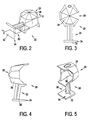
- a bulb shield 20 which is in accordance with one embodiment of the present invention is illustrated in FIGURES 2-6
- a bulb shield 20a which is in accordance with another embodiment of the present invention is illustrated in FIGURE 9
- a bulb shield 20b which is in accordance with still yet another embodiment of the present invention is illustrated in FIGURE 12.
- All three bulb shields 20, 20a, 20b provide several advantages. Each is generally lightweight, inexpensive and easy to make. In addition, each can withstand the high temperatures which are typically experienced in an automotive headlamp assembly.
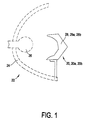
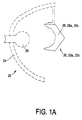
- FIGURES 1 and 1A depict how any one of the bulb shields 20, 20a, 20b are envisioned to be incorporated into an automotive headlamp assembly 22.
- the headlamp assembly 22 includes a reflector 24 and a headlamp bulb 26 disposed in the reflector 24.
- the bulb shield 20, 20a, 20b is mounted to the reflector 24. While FIGURE 1 shows the bulb shield 20, 20a, 20b bottom-mounted in the assembly 22, FIGURE 1A shows the bulb shield 20, 20a, 20b top-mounted in the assembly.
- the bulb shield 20, 20a, 20b is bottom-mounted or top-mounted, preferably the bulb shield 20, 20a, 20b is mounted to the reflector 24 or some other proximate structure such that a cup portion 28, 28a, 28b of the bulb shield 20, 20a, 20b is generally horizontally aligned with the headlamp bulb 26.
- Such alignment between the headlamp bulb 26 and the cup portion 28, 28a, 28b of the bulb shield 20, 20a, 20b causes the cup portion 28, 28a, 28b to block or eliminate the "hot spot" which would otherwise be viewable by, for example, an oncoming driver who looks in the direction of the projected headlamp beam.
- the bulb shield 20 illustrated in FIGURES 2-7 will now be described.
- the bulb shield 20 includes a cup portion 28 and a stem portion 30 which extends from the cup portion 28.
- it is the end 32 of the stem portion 30 which is configured for mounting the bulb shield 20.
- the end 32 of the stem portion 30 may include a base 34 which is receivable in a corresponding channel, where the channel is provided either on the reflector or on another, proximate structure for mounting the bulb shield 20.
- the stem portion 30 is of a length which provides that when the bulb shield 20 is mounted, the bulb shield 20 is generally aligned with the headlamp bulb 26 (see FIGURE 1) such that the bulb shield 20 eliminates the "hot spot" which would otherwise be caused by the headlamp bulb 26.
- the cup portion 28 of the bulb shield 20 is sharply concave having an inside surface 36 and an outside surface 38, wherein the inside surface 36 generally faces the headlamp bulb 26 when the bulb shield 20 is correctly mounted.
- the cup portion 28 may take some other shape. Regardless of the shape of this portion of the bulb shield 20, preferably the portion 28 is configured to block or eliminate the headlamp beam "hot spot" when the bulb shield 20 is correctly mounted.
- the stem portion 30 of the bulb shield 20 is preferably made of plastic
- the cup portion 28 is preferably made of one or more layers of metal which are disposed on plastic.
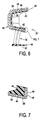
- the bulb shield 20 may comprise a single plastic part including the stem portion 30 and cup portion 28, where the cup portion 28 has one or more metal layers deposited on the plastic. More specifically, as shown in FIGURE 7, preferably the cup portion 28 includes a plastic layer 40, which is effectively the inside surface 36 of the cup portion 28, and a plurality of metal layers 42, 44, 46 deposited on the opposite surface 38 of the cup portion 28.
- the plastic may be a high heat-resistant injection molding material, such as polyphenelene sulfide, "Fortron” or "Ryton.”
- the plurality of metal layers which are layered on the plastic may include a layer 42 of copper which is electro-formed onto the surface of the plastic 40 at a thickness of 0.0100 to 0.0110 inches, a layer 44 of nickel which is plated over the layer 42 of electro-formed copper at a thickness of 0.00015 to 0.0002 inches, and an exterior layer 46 of decorative chrome plated over the nickel plating layer 44 at a thickness of 0.00035 to 0.0005 inches.
- the bulb shield 20 may comprise a single plastic part having a stem portion 30 and a cup portion 28, where the outside surface 38 of the cup portion 28 is layered with copper, nickel and then chrome.
- other materials and/or thicknesses may be utilized.
- the layers 42, 44, 46 of metal on the outside surface 38 of the cup portion 28 of the bulb shield 20 provide that the cup portion 28 can withstand the high temperatures which are experienced by the bulb shield 20 when the bulb shield 20 is employed in an automotive headlamp assembly 22, as shown in FIGURE 1.
- the electro-forming and plating provides that the cup portion 28 becomes captive, so that different thermal coefficients of expansion will permit the materials to grow separately, but still remain attached and assembled.
- the electro-forming and plating also provides that the peripheral surface 48 of the cup portion 28 is shaped and sized to meet precision requirements.
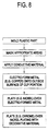
- a plastic part is plastic injection molded. Specifically, preferably a plurality of identical plastic parts are molded simultaneously using a multiple cavity tool.
- the plastic used to mold the part(s) is preferably a high heat-resistant injection molding material, such as polyphenelene sulfide, "Fortron” or "Ryton,” as discussed above.
- Each plastic part provides the stem portion 30 and the inside surface 36 of the cup portion 28, as shown in FIGURES 2-7. Then, preferably, the inside surface 36 of the cup portion 28, as well as the entire stem portion 30, is masked (perhaps by using a masking tool) from electro-forming.
- a generally conductive material such as silver nitrate, is sprayed or otherwise applied to the outside surface 38 of the cup portion 28 of the bulb shield 20.
- a metal material such as copper (type II) at a thickness of 0.0100-0.0110 inches, is electro-formed onto the outside surface 38 of the cup portion 28 (thereby providing layer 42).
- another metal material such as nickel at a thickness of 0.00015-0.0002 inches, is plated over the electro-formed layer 42 of copper (thereby providing layer 44).
- a decorative metal material such as decorative chrome at a thickness of 0.00035-0.005 inches, is plated over the nickel flash (plating) (thereby providing layer 46).
- the plastic layer 40 of the cup portion 28 of the bulb shield 20 functions as a mandrel during the electro-forming, yet remains part of the bulb shield 20.
- a process is simple and easy to perform. Additionally, such a process yields a bulb shield 20 which has desired properties, such as being lightweight and relatively inexpensive, yet meets precision requirements at the peripheral edge 48.
- FIGURE 9 depicts a bulb shield 20a which is in accordance with a second embodiment of the present invention.
- This bulb shield 20a will now be described. Because the bulb shield 20a shown in FIGURE 9 is very similar to the bulb shield 20 shown in FIGURES 2-7, similar reference numerals are used for corresponding parts, and the alphabetic suffix "a" is added.
- the bulb shield 20a like the bulb shield 20 shown in FIGURES 2-7, also includes a stem portion 30a (which preferably includes a mounting base 34a), and a cup portion 28a.
- the bulb shield 20a shown in FIGURE 9 includes a plastic layer 40a which does not extend fully along the inside surface 36a of the cup portion 28a. Instead, the plastic layer 40a extends only along a portion of the inside surface 36a of the cup portion 28a.
- the plastic layer 40a may comprise a high heat-resistant injection molding material, such as polyphenelene sulfide, "Fortron” or "Ryton.” As shown, a layer 42a of metal, such as a layer of electro-formed copper at a thickness of 0.0100 to 0.0110, is provided at the area where the inside surface 36a of the cup portion 28a does not include plastic. While FIGURE 9 depicts the situation where the bulb shield 20a is configured for bottom-mounting within an assembly 22 (see FIGURE 1), the bulb shield 20a may instead be configured for top mounting (see FIGURE 1A).
- the bulb shield 20a shown in FIGURE 9 also preferably includes a layer 44a of nickel which is plated over the layer 42a of electro-formed copper at a thickness of 0.00015 to 0.0002 inches, and an exterior layer 46a of decorative chrome plated over the nickel plating at a thickness of 0.00035 to 0.0005 inches.
- a layer 44a of nickel which is plated over the layer 42a of electro-formed copper at a thickness of 0.00015 to 0.0002 inches
- an exterior layer 46a of decorative chrome plated over the nickel plating at a thickness of 0.00035 to 0.0005 inches.
- other materials and/or thicknesses may be utilized.
- the layers 42a, 44a, 46a of metal on the outside surface 38a of the cup portion 28a of the bulb shield 20a provide that the cup portion 28a can withstand the high temperatures which are experienced by the bulb shield 20a when employed in an automotive headlamp assembly 22.
- the electro-forming provides that inner layers of the cup portion 28a become captive, so that different thermal coefficients of expansion will still permit the materials to grow separately, but still remain attached and assembled.
- the electro-forming also provides that the peripheral surface 48a of the cup portion 28a can be metal, yet can still meet precision requirements and at a reasonable cost.
- a plastic part is two-shot plastic injection molded.
- a relatively low melt plastic such as polystyrene (230° Fahrenheit melt) is two shot molded with a relatively high melt plastic, such as PPS (510° Fahrenheit deflection temperature).
- PPS 510° Fahrenheit deflection temperature
- the layer 42a of metal material such as copper at a thickness of 0.0100 to 0.0110 inches, is electro-formed onto the outside surface 38a of the cup portion 28a, onto the surface of the lower melt plastic 62.
- a layer 44a of nickel is plated over the layer 42a of electro-formed copper at a thickness of 0.00015 to 0.0002 inches (thereby providing that which is shown in FIGURE 11).
- the outside surface of the cup portion of the plastic part 60 functions as a mandrel for the electro-forming.
- the piece 60 is baked, such as at a temperature of 350° Fahrenheit, to melt away the lower melt plastic portion 62 of the cup portion 28a.
- the inside surface 36a of the cup portion 28a is black finished, and the outside surface 38a of the cup portion 28a is decorative plated, such as with a layer 46a of chrome, for example at a thickness of 0.00035 to 0.0005 inches (thereby providing that which is shown in FIGURE 9).
- FIGURE 12 A bulb shield 20b which is in accordance with yet another embodiment of the present invention is shown in FIGURE 12, and will now be described. Because the bulb shield 20b shown in FIGURE 12 is very similar to the bulb shields 20 and 20a shown in FIGURES 2-7 and 9, respectively, similar reference numerals are used for corresponding parts, and the alphabetic suffix "b" is used.
- the bulb shield 20b includes a stem portion 30b made of metal, such as steel, and a cup portion 28b made of a plurality of metal layers 42b, 44b, 46b, such as copper, nickel and decorative chrome.
- the cup portion 28b is heat staked to the stem portion 30b, and the copper layer 42b is electro-formed such that the electro-forming further secures the cup portion 28b to the stem portion 30b.
- a mandrel 69 is plastic injection molded, and then is heat staked to the stem portion 30b, which, as mentioned above, is preferably formed of steel (thereby providing that which is shown in FIGURE 14).
- the mandrel 69 may include a receptacle slot and small studs to facilitate the heat staking.
- a conductive material such as silver nitrate, is sprayed or otherwise applied to the outside surface 38b of the mandrel 69.
- a metal layer 42b such as copper at a thickness of 0.005-0.006, is electro-formed onto the conductive material, thereby providing that which is illustrated in FIGURE 14.
- the electro-forming further secures the stem portion 30b to the mandrel 69.
- the overall assembly is baked to melt away the mandrel 69.
- the assembly is nickel flashed (thereby providing layer 44b) and chrome plated (thereby providing layer 46b), thereby providing that which is illustrated in FIGURE 12.
- a thru slot may be provided in the cup portion 28b of the bulb shield 20b.
- each of the bulb shields 20, 20a, 20b described hereinabove is lightweight and relatively inexpensive to make. Additionally, the peripheral surface 48, 48a, 48b of the cup portion 28, 28a, 28b of each meets precision requirements. Also, each of the methods described hereinabove is simple and relatively inexpensive to perform.
Landscapes
- Engineering & Computer Science (AREA)
- General Engineering & Computer Science (AREA)
- Non-Portable Lighting Devices Or Systems Thereof (AREA)
Applications Claiming Priority (2)
| Application Number | Priority Date | Filing Date | Title |
|---|---|---|---|
| US14997299P | 1999-08-20 | 1999-08-20 | |
| US149972P | 1999-08-20 |
Publications (3)
| Publication Number | Publication Date |
|---|---|
| EP1079173A2 true EP1079173A2 (de) | 2001-02-28 |
| EP1079173A3 EP1079173A3 (de) | 2004-01-14 |
| EP1079173B1 EP1079173B1 (de) | 2006-09-13 |
Family
ID=22532590
Family Applications (1)
| Application Number | Title | Priority Date | Filing Date |
|---|---|---|---|
| EP20000202456 Expired - Lifetime EP1079173B1 (de) | 1999-08-20 | 2000-07-10 | Durch Elektroformung hergestellte Lichtblende und entsprechendes Herstellungsverfahren |
Country Status (5)
| Country | Link |
|---|---|
| US (1) | US6375341B1 (de) |
| EP (1) | EP1079173B1 (de) |
| CA (1) | CA2313419A1 (de) |
| DE (1) | DE60030648T2 (de) |
| ES (1) | ES2270785T3 (de) |
Cited By (5)
| Publication number | Priority date | Publication date | Assignee | Title |
|---|---|---|---|---|
| US7021804B2 (en) | 2003-08-13 | 2006-04-04 | Guide Corporation | Lamp assembly with multi-stage reflector |
| US7033054B2 (en) | 2003-08-13 | 2006-04-25 | Guide Corporation | Lamp assembly with peripheral auxiliary function |
| EP1432950A4 (de) * | 2001-10-05 | 2007-05-02 | Elco Textron Inc | Lichtblende |
| EP1778522A4 (de) * | 2004-08-16 | 2009-04-29 | Illume Llc | Hitzeresistenter glühbirnenschirm |
| CN101234618B (zh) * | 2007-02-01 | 2012-05-30 | 福特全球技术公司 | 汽车前照灯灯泡罩 |
Families Citing this family (7)
| Publication number | Priority date | Publication date | Assignee | Title |
|---|---|---|---|---|
| US6890090B2 (en) * | 2001-08-08 | 2005-05-10 | Automotive Lighting Reutlingen Gmbh | Headlight for a motor vehicle |
| DE10311688B4 (de) * | 2003-03-17 | 2007-06-06 | Volkswagen Ag | Leuchtvorrichtung für Fahrzeuge |
| EA009340B1 (ru) | 2003-07-29 | 2007-12-28 | Турхан Алджелик | Фара для непрерывного дальнего света без ослепляющего действия |
| US7014346B2 (en) * | 2004-03-08 | 2006-03-21 | Valeo Sylvania L.L.C. | Light shield mounting for automotive headlamp |
| US7891851B2 (en) * | 2005-04-05 | 2011-02-22 | Turhan Alcelik | Headlamp with long-distance illumination without glaring effect |
| US7748881B2 (en) * | 2007-01-08 | 2010-07-06 | Isatec Of Ohio, Inc. | Tailor welded strip bulb shield |
| CN101880899B (zh) * | 2010-07-12 | 2012-09-26 | 中山市琪朗灯饰厂有限公司 | 一种灯饰配件及制造灯饰配件的电铸沉积方法 |
Family Cites Families (10)
| Publication number | Priority date | Publication date | Assignee | Title |
|---|---|---|---|---|
| US3796886A (en) * | 1973-05-18 | 1974-03-12 | Ervin J | Radiant energy reflectors |
| US5497299A (en) | 1994-12-12 | 1996-03-05 | General Motors Corporation | Headlamp assembly with hook-in bulb shield |
| US5497298A (en) | 1994-12-12 | 1996-03-05 | General Motors Corporation | Headlamp assembly with coil spring bulb shield |
| EP0812004B1 (de) | 1996-06-04 | 2003-07-09 | Honda Giken Kogyo Kabushiki Kaisha | Lampenbirne für Fahrzeuge |
| ES2176655T3 (es) * | 1996-08-15 | 2002-12-01 | Alcan Tech & Man Ag | Reflector con superficie resistente. |
| US5962973A (en) | 1997-06-06 | 1999-10-05 | Guide Corporation | Optically-coated dual-filament bulb for single compartment headlamp |
| US6010236A (en) | 1998-04-08 | 2000-01-04 | Lai; Wei-Cheng | Connector for connecting a bulb holder with a lamp shield |
| DE19824053A1 (de) * | 1998-05-29 | 1999-12-02 | Hella Kg Hueck & Co | Beleuchtungseinrichtung für Fahrzeuge |
| US6012830A (en) * | 1998-06-23 | 2000-01-11 | Valeo Sylvania L.L.C. | Light shield for a vehicle headlamp |
| JP3949300B2 (ja) | 1998-11-20 | 2007-07-25 | 株式会社小糸製作所 | 車両用前照灯 |
-
2000
- 2000-05-18 US US09/574,158 patent/US6375341B1/en not_active Expired - Fee Related
- 2000-07-05 CA CA002313419A patent/CA2313419A1/en not_active Abandoned
- 2000-07-10 ES ES00202456T patent/ES2270785T3/es not_active Expired - Lifetime
- 2000-07-10 DE DE2000630648 patent/DE60030648T2/de not_active Expired - Fee Related
- 2000-07-10 EP EP20000202456 patent/EP1079173B1/de not_active Expired - Lifetime
Non-Patent Citations (1)
| Title |
|---|
| None |
Cited By (5)
| Publication number | Priority date | Publication date | Assignee | Title |
|---|---|---|---|---|
| EP1432950A4 (de) * | 2001-10-05 | 2007-05-02 | Elco Textron Inc | Lichtblende |
| US7021804B2 (en) | 2003-08-13 | 2006-04-04 | Guide Corporation | Lamp assembly with multi-stage reflector |
| US7033054B2 (en) | 2003-08-13 | 2006-04-25 | Guide Corporation | Lamp assembly with peripheral auxiliary function |
| EP1778522A4 (de) * | 2004-08-16 | 2009-04-29 | Illume Llc | Hitzeresistenter glühbirnenschirm |
| CN101234618B (zh) * | 2007-02-01 | 2012-05-30 | 福特全球技术公司 | 汽车前照灯灯泡罩 |
Also Published As
| Publication number | Publication date |
|---|---|
| DE60030648D1 (de) | 2006-10-26 |
| US6375341B1 (en) | 2002-04-23 |
| EP1079173B1 (de) | 2006-09-13 |
| DE60030648T2 (de) | 2007-10-04 |
| EP1079173A3 (de) | 2004-01-14 |
| CA2313419A1 (en) | 2001-02-20 |
| ES2270785T3 (es) | 2007-04-16 |
Similar Documents
| Publication | Publication Date | Title |
|---|---|---|
| EP1079173B1 (de) | Durch Elektroformung hergestellte Lichtblende und entsprechendes Herstellungsverfahren | |
| KR101093516B1 (ko) | 자동차용 라디에이터 그릴 | |
| US4570203A (en) | Light reflector apparatus and method of making | |
| US6132068A (en) | Vehicular headlamp having a shade | |
| US6776515B2 (en) | Bulb shield | |
| GB2129366A (en) | Light reflector apparatus and method of making same | |
| US12379088B2 (en) | Automotive trim component | |
| US6347881B1 (en) | Vehicle lamp | |
| MXPA00007807A (en) | Electro-formed bulb shield and method of making same | |
| CN105235153A (zh) | 光学零件的制造方法、制造装置和光学零件 | |
| CN101084099B (zh) | 耐热塑料灯组件及形成方法 | |
| US7156543B2 (en) | Vehicle lamp | |
| EP0716757B1 (de) | Verbindungssystem für eine brillenfassung | |
| KR101092631B1 (ko) | 자동차용 라디에이터 그릴 제조방법 | |
| CN115476779A (zh) | 一种汽车饰件及汽车饰件的制造方法 | |
| JP2000306405A (ja) | 車両用灯具 | |
| US20250052537A1 (en) | Metal reinforced target sight | |
| JPWO2016002601A1 (ja) | 金型及び灯具用エクステンション | |
| US20240165900A1 (en) | Hidden lighting film lens formation apparatus and hidden lighting film lens | |
| JP2001315168A (ja) | 射出成形用金型 | |
| CN109424877B (zh) | 一种车载灯具的装配方法、装配结构及车载灯具 | |
| DE102023211489A1 (de) | Verfahren zur Herstellung eines Trägerelements mit einem integrierten optischen Element | |
| GB2165182A (en) | Light reflector apparatus and method of making same | |
| HK1013865B (en) | Connecting system for an eyewear frame | |
| JP2004039546A (ja) | 車両用灯具およびその製造方法 |
Legal Events
| Date | Code | Title | Description |
|---|---|---|---|
| PUAI | Public reference made under article 153(3) epc to a published international application that has entered the european phase |
Free format text: ORIGINAL CODE: 0009012 |
|
| AK | Designated contracting states |
Kind code of ref document: A2 Designated state(s): AT BE CH CY DE DK ES FI FR GB GR IE IT LI LU MC NL PT SE |
|
| AX | Request for extension of the european patent |
Free format text: AL;LT;LV;MK;RO;SI |
|
| 17P | Request for examination filed |
Effective date: 20010323 |
|
| PUAL | Search report despatched |
Free format text: ORIGINAL CODE: 0009013 |
|
| AK | Designated contracting states |
Kind code of ref document: A3 Designated state(s): AT BE CH CY DE DK ES FI FR GB GR IE IT LI LU MC NL PT SE |
|
| AX | Request for extension of the european patent |
Extension state: AL LT LV MK RO SI |
|
| RIC1 | Information provided on ipc code assigned before grant |
Ipc: 7F 21W 101:10 Z Ipc: 7C 25D 11/00 B Ipc: 7C 25D 1/00 B Ipc: 7F 21V 7/22 B Ipc: 7F 21V 11/16 B Ipc: 7F 21S 8/12 A |
|
| AKX | Designation fees paid |
Designated state(s): DE ES FR GB IT |
|
| GRAP | Despatch of communication of intention to grant a patent |
Free format text: ORIGINAL CODE: EPIDOSNIGR1 |
|
| GRAS | Grant fee paid |
Free format text: ORIGINAL CODE: EPIDOSNIGR3 |
|
| GRAA | (expected) grant |
Free format text: ORIGINAL CODE: 0009210 |
|
| AK | Designated contracting states |
Kind code of ref document: B1 Designated state(s): DE ES FR GB IT |
|
| PG25 | Lapsed in a contracting state [announced via postgrant information from national office to epo] |
Ref country code: IT Free format text: LAPSE BECAUSE OF FAILURE TO SUBMIT A TRANSLATION OF THE DESCRIPTION OR TO PAY THE FEE WITHIN THE PRESCRIBED TIME-LIMIT;WARNING: LAPSES OF ITALIAN PATENTS WITH EFFECTIVE DATE BEFORE 2007 MAY HAVE OCCURRED AT ANY TIME BEFORE 2007. THE CORRECT EFFECTIVE DATE MAY BE DIFFERENT FROM THE ONE RECORDED. Effective date: 20060913 |
|
| REG | Reference to a national code |
Ref country code: GB Ref legal event code: FG4D |
|
| REF | Corresponds to: |
Ref document number: 60030648 Country of ref document: DE Date of ref document: 20061026 Kind code of ref document: P |
|
| ET | Fr: translation filed | ||
| REG | Reference to a national code |
Ref country code: ES Ref legal event code: FG2A Ref document number: 2270785 Country of ref document: ES Kind code of ref document: T3 |
|
| REG | Reference to a national code |
Ref country code: GB Ref legal event code: 732E |
|
| RAP2 | Party data changed (patent owner data changed or rights of a patent transferred) |
Owner name: ACUMENT INTELLECTUAL PROPERTIES, LLC. |
|
| PLBE | No opposition filed within time limit |
Free format text: ORIGINAL CODE: 0009261 |
|
| STAA | Information on the status of an ep patent application or granted ep patent |
Free format text: STATUS: NO OPPOSITION FILED WITHIN TIME LIMIT |
|
| 26N | No opposition filed |
Effective date: 20070614 |
|
| GBPC | Gb: european patent ceased through non-payment of renewal fee |
Effective date: 20070710 |
|
| PG25 | Lapsed in a contracting state [announced via postgrant information from national office to epo] |
Ref country code: DE Free format text: LAPSE BECAUSE OF NON-PAYMENT OF DUE FEES Effective date: 20080201 |
|
| PG25 | Lapsed in a contracting state [announced via postgrant information from national office to epo] |
Ref country code: GB Free format text: LAPSE BECAUSE OF NON-PAYMENT OF DUE FEES Effective date: 20070710 |
|
| REG | Reference to a national code |
Ref country code: FR Ref legal event code: ST Effective date: 20080331 |
|
| PG25 | Lapsed in a contracting state [announced via postgrant information from national office to epo] |
Ref country code: FR Free format text: LAPSE BECAUSE OF NON-PAYMENT OF DUE FEES Effective date: 20070731 |
|
| REG | Reference to a national code |
Ref country code: ES Ref legal event code: FD2A Effective date: 20070711 |
|
| PG25 | Lapsed in a contracting state [announced via postgrant information from national office to epo] |
Ref country code: ES Free format text: LAPSE BECAUSE OF NON-PAYMENT OF DUE FEES Effective date: 20070711 |