EP1079213A2 - Procédé de commande d'un dispositif oscillant pour débitmètre de Coriolis - Google Patents
Procédé de commande d'un dispositif oscillant pour débitmètre de Coriolis Download PDFInfo
- Publication number
- EP1079213A2 EP1079213A2 EP00116741A EP00116741A EP1079213A2 EP 1079213 A2 EP1079213 A2 EP 1079213A2 EP 00116741 A EP00116741 A EP 00116741A EP 00116741 A EP00116741 A EP 00116741A EP 1079213 A2 EP1079213 A2 EP 1079213A2
- Authority
- EP
- European Patent Office
- Prior art keywords
- signal
- pulse width
- supply circuit
- width modulation
- modulation signal
- Prior art date
- Legal status (The legal status is an assumption and is not a legal conclusion. Google has not performed a legal analysis and makes no representation as to the accuracy of the status listed.)
- Withdrawn
Links
Images

Classifications
-
- G—PHYSICS
- G01—MEASURING; TESTING
- G01F—MEASURING VOLUME, VOLUME FLOW, MASS FLOW OR LIQUID LEVEL; METERING BY VOLUME
- G01F1/00—Measuring the volume flow or mass flow of fluid or fluent solid material wherein the fluid passes through a meter in a continuous flow
- G01F1/76—Devices for measuring mass flow of a fluid or a fluent solid material
- G01F1/78—Direct mass flowmeters
- G01F1/80—Direct mass flowmeters operating by measuring pressure, force, momentum, or frequency of a fluid flow to which a rotational movement has been imparted
- G01F1/84—Coriolis or gyroscopic mass flowmeters
- G01F1/8409—Coriolis or gyroscopic mass flowmeters constructional details
- G01F1/8422—Coriolis or gyroscopic mass flowmeters constructional details exciters
-
- G—PHYSICS
- G01—MEASURING; TESTING
- G01F—MEASURING VOLUME, VOLUME FLOW, MASS FLOW OR LIQUID LEVEL; METERING BY VOLUME
- G01F1/00—Measuring the volume flow or mass flow of fluid or fluent solid material wherein the fluid passes through a meter in a continuous flow
- G01F1/76—Devices for measuring mass flow of a fluid or a fluent solid material
- G01F1/78—Direct mass flowmeters
- G01F1/80—Direct mass flowmeters operating by measuring pressure, force, momentum, or frequency of a fluid flow to which a rotational movement has been imparted
- G01F1/84—Coriolis or gyroscopic mass flowmeters
- G01F1/8409—Coriolis or gyroscopic mass flowmeters constructional details
- G01F1/8431—Coriolis or gyroscopic mass flowmeters constructional details electronic circuits
Definitions
- the invention relates on the one hand to a method for actuating a vibration generator, the on a Coriolis line of a Coriolis mass flow meter for flowing media acts, and on the other hand a supply circuit for one Vibration generator of a mass flow meter for flowing media, the works on the Coriolis principle.
- the measuring method of a mass flow meter for flowing media works based on the Coriolis line of the mass flow meter brought into vibration with the help of a vibration generator becomes, whereby the medium flowing through the Coriolis line Coriolis forces experiences, the detection of which is a measure of the mass flow through the Coriolis line delivers through.
- the vibration generator typically instructs System consisting of a coil and a magnet, either the coil or the Magnet is firmly connected to the Coriolis line, so that an alternating excitation this system, i.e. an alternating movement of the magnet in the coil in or out of this, to a vibration excitation of the Coriolis line leads.
- the vibration amplitude of the Coriolis line is typically with the help of an analog amplifier circuit to the im Medium Coriolis forces to be achieved. This is the current vibration amplitude the Coriolis line with the help of an attached to the Coriolis line Sensor detected, the detected amplitude value is with a target value for the Amplitude value compared, and depending on the deviation of the detected Amplitude value from the target value for the amplitude value becomes a sinusoidal Excitation signal amplified by a corresponding amount and into the coil of the Vibration generator fed.
- the object shown and derived above is according to the invention by a method solved, in which the vibration generator with a pulse width modulated pulsed sine signal is fed.
- the vibration generator with a pulse width modulated pulsed sine signal is fed.
- it is therefore not a continuous one Sinus signal used to feed the vibration generator, but a pulsed sine signal.
- the control of those transmitted with the signal takes place Energy via pulse width modulation of the pulsed sine signal.
- the pulsed Sinusoidal signal essentially the same energy as with one continuous sine signal must be fed into the vibration generator, is the amplitude of the pulse width modulated pulsed sine signal in its entirety areas other than zero always larger than the amplitude of the continuous sinusoidal signal.
- the excitation signal in the case of the pulse width modulated pulsed sinusoidal signal always significantly closer to the maximum with of the amplifier circuit achievable signal value held as the continuous sine signal.
- the optimal efficiency of the amplifier circuit is only in the fully blocked or achieved in the fully switched state. In the reinforcement areas in between, however, there is considerable energy loss due to heat loss in the amplifier circuit. These energy losses decrease, however, with increasing passage of the amplifier circuit. Thus achieved that the efficiency of signal amplification in the case of pulse width modulated pulsed sinusoidal signal is significantly better than in the case of the continuous sinusoidal signal, there when using the pulse width modulated pulsed sine signal in the amplifier circuit lower heat losses occur.
- the efficiency of the Gain is optimal anyway, since no current flows and therefore no current in Heat loss can be implemented.
- the method according to the invention is particularly advantageous. by generating the pulse width modulated pulsed sine signal using a multiplexer with which a pulse width modulation signal is multiplied by an unpulsed Sinusoidal signal that has a constant predetermined frequency.
- the pulse duty factor of the pulse width modulation signal i.e. the width of the individual Pulses of the pulse width modulation signal in relation to their distance from one another, is preferably done with the help of a PID controller (proportional-integral-differential Controller). Only the width of the pulses is changed; their distance from each other remains constant.
- PID controller proportional-integral-differential Controller
- a particularly effective regulation of the pulse width modulation can then be achieved when setting the duty cycle of the pulse width modulation signal in the PID controller is set taking into account an error signal that from the Difference between the deflection of the Coriolis line measured by a sensor on the one hand and a predetermined deflection setpoint on the other hand becomes.
- This regulation is further simplified in an advantageous manner if the amplitude of the pulse width modulation signal is kept constant.
- the frequency of the pulse width modulation signal is clear is greater than the frequency of the unpulsed sinusoidal signal.
- the unpulsed sinusoidal signal essentially the resonance frequency of the Coriolis line, is achieved in the frequency range of the pulse width modulation signal practically no vibrations are transmitted to the Coriolis line, which causes further energy losses due to interference vibrations of the Coriolis line prevents.
- the object shown and derived above is further according to the invention solved by a supply circuit in which the vibration generator of the mass flow meter from the supply circuit with a pulse width modulated pulsed sine signal can be controlled.
- the supply circuit shows preferably on the output side an amplifier via which the vibration generator is fed.
- the supply circuit is advantageously designed according to the invention in that that the supply circuit has a multiplexer with which a pulse width modulation signal can be multiplied by an unpulsed sinusoidal signal has a constant predetermined frequency.
- the vibration generator 1 is a supply circuit schematically according to the embodiment of the invention for a vibration generator of a Coriolis mass flow meter visible for flowing media.
- the vibrational excitement of the Coriolis conduction is carried out by means of a vibration generator 1, one of which is not shown Coil and one attached to the Coriolis line, also not shown Has magnets.
- the vibration generator 1 is fed via a in the supply circuit amplifier 2 provided on the output side.
- Amplifier 2 in turn a signal generated in a multiplexer 3 is supplied.
- the multiplexer 3 is controlled on the one hand by a freely programmable gate array 4, the structure of which is shown schematically in FIG. 2.
- the freely programmable Gate array 4 has a PID controller 5, a comparison unit 6 and one digital rectifier 7. Via an A / D converter 8 and one in the supply circuit the amplifier 9 provided on the input side is the gate array 4 a sensor 10 attached to the Coriolis line.
- the multiplexer 3 is switched on via an upstream amplifier 11 from the sensor 10 attached to the Coriolis line and from the input side Amplifier 9 fed amplified signal.
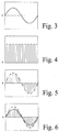
- This signal corresponds to essentially a continuous, unpulsed sinusoidal signal, as can be seen from FIG. 3.
- That fed to the multiplexer 3 from the freely programmable gate array 4 Signal is a pulse width modulation signal with constant frequency, like from Fig. 4 can be seen.
- That detected by the sensor 10 and amplified by the input amplifier 9 Signal is digitized by the A / D converter 8 and then in the freely programmable Gate array 4 fed. There the signal is first digital Rectifier 7 rectified and then in the comparison unit 6 with a target value for the amplitude of the vibration of the Coriolis line compared. The comparison unit 6 generates depending on the difference between this setpoint and the detected actual value of the vibration amplitude an error value F.
- the pulse width modulation generator 12 also provided in the gate array 4 Pulse width modulation signal generated and from there fed into the multiplexer 3. Finally, the continuous sine signal shown in FIG. 3 is in the multiplexer 3 multiplied by the pulse width modulation signal shown in FIG. 4. The result is the pulse-width-modulated pulsed sine signal shown in FIG. 5, that via the output-side amplifier 2 to feed the vibration generator 1 is used.
- the efficiency of this circuit i. H. the efficiency of pulse width modulated pulsed sine signal, much higher than the conventional one Circuit in which a continuous sinusoidal signal is fed to the oscillator 1 is used.
- the pulse width modulated pulsed sine signal In all areas where the pulse width modulated pulsed sine signal is different from zero, its amplitude is clearly above that of the continuous sine signal.
- the Greatest efficiency due to the lowest heat loss in the amplifier circuit then when the amplifier - according to the embodiment of the invention transistor-based amplifier - completely blocks or completely opens Pass is switched and the efficiency of the non-zero signal is around the bigger the signal, the bigger.
- the pulse-width-modulated, pulsed sinusoidal signal an efficiency of 78% while the continuous sine wave only has an efficiency of 55%.
Landscapes
- Physics & Mathematics (AREA)
- Fluid Mechanics (AREA)
- General Physics & Mathematics (AREA)
- Measuring Volume Flow (AREA)
- Apparatuses For Generation Of Mechanical Vibrations (AREA)
Applications Claiming Priority (2)
| Application Number | Priority Date | Filing Date | Title |
|---|---|---|---|
| DE19939157A DE19939157B4 (de) | 1999-08-20 | 1999-08-20 | Verfahren zum Ansteuern eines Schwingungserzeugers und Versorgungsschaltung für einen Schwingungserzeuger |
| DE19939157 | 1999-08-20 |
Publications (2)
| Publication Number | Publication Date |
|---|---|
| EP1079213A2 true EP1079213A2 (fr) | 2001-02-28 |
| EP1079213A3 EP1079213A3 (fr) | 2002-03-13 |
Family
ID=7918789
Family Applications (1)
| Application Number | Title | Priority Date | Filing Date |
|---|---|---|---|
| EP00116741A Withdrawn EP1079213A3 (fr) | 1999-08-20 | 2000-08-03 | Procédé de commande d'un dispositif oscillant pour débitmètre de Coriolis |
Country Status (4)
| Country | Link |
|---|---|
| US (1) | US6505518B1 (fr) |
| EP (1) | EP1079213A3 (fr) |
| JP (1) | JP3834195B2 (fr) |
| DE (1) | DE19939157B4 (fr) |
Cited By (3)
| Publication number | Priority date | Publication date | Assignee | Title |
|---|---|---|---|---|
| WO2002103302A3 (fr) * | 2001-06-19 | 2003-09-18 | Flowtec Ag | Circuits d'excitation destines a des dispositifs de mesure de debit de masse de coriolis |
| US6662120B2 (en) | 2001-06-19 | 2003-12-09 | Endress + Hauser Flowtec Ag | Excitation circuits for coriolis mass flowmeters |
| US7634939B2 (en) | 2001-06-19 | 2009-12-22 | Endress + Hauser Flowtec Ag | Viscometer |
Families Citing this family (10)
| Publication number | Priority date | Publication date | Assignee | Title |
|---|---|---|---|---|
| DE10200768B4 (de) * | 2001-12-06 | 2004-03-11 | Krohne Ag | Massendurchflussmessgerät und Verfahren zum Betrieb eines Massendurchflussmessgerätes |
| JP4931389B2 (ja) * | 2005-09-12 | 2012-05-16 | 株式会社山武 | 圧力波発生装置及び圧力波発生装置の駆動方法 |
| DE102017131199A1 (de) | 2017-12-22 | 2019-06-27 | Endress + Hauser Flowtec Ag | Coriolis-Massendurchfluß-Meßgerät |
| CN113242960B (zh) | 2018-12-20 | 2024-05-14 | 恩德斯+豪斯流量技术股份有限公司 | 科里奥利质量流量计 |
| DE102018133117A1 (de) | 2018-12-20 | 2020-06-25 | Endress+Hauser Flowtec Ag | Coriolis-Massendurchfluß-Meßgerät |
| EP3899448B1 (fr) | 2018-12-21 | 2024-03-27 | Endress + Hauser Flowtec AG | Débitmètre massique à effet coriolis muni d'un détecteur de champ magnétique |
| DE102019133610A1 (de) | 2019-12-09 | 2021-06-10 | Endress + Hauser Flowtec Ag | Vibronisches Meßsystem zum Messen eines Massestroms eines fluiden Meßstoff |
| DE102020127382A1 (de) | 2020-10-16 | 2022-04-21 | Endress+Hauser Flowtec Ag | Verfahren zum Überprüfen eines vibronischen Meßsystems |
| DE102022112523A1 (de) | 2022-05-18 | 2023-11-23 | Endress+Hauser Flowtec Ag | Vibronisches Meßsystem |
| DE102022116111A1 (de) | 2022-06-28 | 2023-12-28 | Endress+Hauser Flowtec Ag | Vibronisches Meßsystem |
Citations (4)
| Publication number | Priority date | Publication date | Assignee | Title |
|---|---|---|---|---|
| DE3539647A1 (de) * | 1985-11-08 | 1987-05-14 | Bbc Brown Boveri & Cie | Schaltungsanordnung fuer einen pulsgesteuerten wechselstromsteller |
| DE19525253A1 (de) * | 1994-07-11 | 1996-01-18 | Yokogawa Electric Corp | Coriolis-Massendurchflußmesser |
| DE19532377A1 (de) * | 1994-08-12 | 1997-03-06 | Robert Seuffer Gmbh & Co | Verfahren und Vorrichtung zur Versorgung einer Wechselstromlast |
| US5869770A (en) * | 1994-07-21 | 1999-02-09 | Fuji Electric Co., Ltd. | Corioliz type mass flowmeter having isolation form external vibration |
Family Cites Families (12)
| Publication number | Priority date | Publication date | Assignee | Title |
|---|---|---|---|---|
| US4467644A (en) * | 1980-12-04 | 1984-08-28 | Palmer James K | Flow meter |
| US4655089A (en) * | 1985-06-07 | 1987-04-07 | Smith Meter Inc. | Mass flow meter and signal processing system |
| GB8516032D0 (en) * | 1985-06-25 | 1985-07-31 | Bestobell Sparling Ltd | Fluid flow monitoring |
| US4793195A (en) * | 1986-10-20 | 1988-12-27 | Northrop Corporation | Vibrating cylinder gyroscope and method |
| GB8829825D0 (en) * | 1988-12-21 | 1989-02-15 | Schlumberger Ind Ltd | A combined output and drive circuit for a mass flow transducer |
| US5009109A (en) * | 1989-12-06 | 1991-04-23 | Micro Motion, Inc. | Flow tube drive circuit having a bursty output for use in a coriolis meter |
| US5557076A (en) * | 1993-11-12 | 1996-09-17 | Mikron Gesellschaft Fur | Cordless position detection apparatus |
| DE4423168C2 (de) * | 1994-07-04 | 1998-09-24 | Krohne Ag | Massendurchflußmeßgerät |
| US5678643A (en) * | 1995-10-18 | 1997-10-21 | Halliburton Energy Services, Inc. | Acoustic logging while drilling tool to determine bed boundaries |
| US5777238A (en) * | 1996-06-12 | 1998-07-07 | Welch Allyn, Inc. | Driver-receiver apparatus for use with ultrasonic flowmeters |
| DE59800051D1 (de) * | 1997-03-21 | 1999-12-30 | Flowtec Ag | Mess- und Betriebsschaltung eines Coriolis-Massedurchflussmessers |
| US6073495A (en) * | 1997-03-21 | 2000-06-13 | Endress + Hauser Flowtec Ag | Measuring and operating circuit of a coriolis-type mass flow meter |
-
1999
- 1999-08-20 DE DE19939157A patent/DE19939157B4/de not_active Expired - Fee Related
-
2000
- 2000-08-03 EP EP00116741A patent/EP1079213A3/fr not_active Withdrawn
- 2000-08-11 US US09/637,727 patent/US6505518B1/en not_active Expired - Fee Related
- 2000-08-21 JP JP2000250229A patent/JP3834195B2/ja not_active Expired - Fee Related
Patent Citations (4)
| Publication number | Priority date | Publication date | Assignee | Title |
|---|---|---|---|---|
| DE3539647A1 (de) * | 1985-11-08 | 1987-05-14 | Bbc Brown Boveri & Cie | Schaltungsanordnung fuer einen pulsgesteuerten wechselstromsteller |
| DE19525253A1 (de) * | 1994-07-11 | 1996-01-18 | Yokogawa Electric Corp | Coriolis-Massendurchflußmesser |
| US5869770A (en) * | 1994-07-21 | 1999-02-09 | Fuji Electric Co., Ltd. | Corioliz type mass flowmeter having isolation form external vibration |
| DE19532377A1 (de) * | 1994-08-12 | 1997-03-06 | Robert Seuffer Gmbh & Co | Verfahren und Vorrichtung zur Versorgung einer Wechselstromlast |
Cited By (3)
| Publication number | Priority date | Publication date | Assignee | Title |
|---|---|---|---|---|
| WO2002103302A3 (fr) * | 2001-06-19 | 2003-09-18 | Flowtec Ag | Circuits d'excitation destines a des dispositifs de mesure de debit de masse de coriolis |
| US6662120B2 (en) | 2001-06-19 | 2003-12-09 | Endress + Hauser Flowtec Ag | Excitation circuits for coriolis mass flowmeters |
| US7634939B2 (en) | 2001-06-19 | 2009-12-22 | Endress + Hauser Flowtec Ag | Viscometer |
Also Published As
| Publication number | Publication date |
|---|---|
| US6505518B1 (en) | 2003-01-14 |
| EP1079213A3 (fr) | 2002-03-13 |
| JP2001099689A (ja) | 2001-04-13 |
| DE19939157A1 (de) | 2001-04-05 |
| JP3834195B2 (ja) | 2006-10-18 |
| DE19939157B4 (de) | 2005-06-23 |
Similar Documents
| Publication | Publication Date | Title |
|---|---|---|
| EP1318385B1 (fr) | Débitmètre massique et procédé de fonctionnement d'un débitmètre massique | |
| EP1079213A2 (fr) | Procédé de commande d'un dispositif oscillant pour débitmètre de Coriolis | |
| DE102006052060B4 (de) | Verfahren und Anordnung zur Anregung einer Gaslaseranordnung | |
| DE3505166A1 (de) | Massendurchfluss-messgeraet nach dem coriolis-prinzip | |
| DE102006043878B4 (de) | Motorregelungsschaltkreis | |
| EP1876428A1 (fr) | Procédé de fonctionnement d'un appareil de mesure du débit massique de Coriolis | |
| DE1488534B2 (de) | Schaltung zur Erzeugung von in der Phasenlage verschiebbaren Impulsen zur Stromsteuerung von Antriebsmagneten für Vibrationsgeräte | |
| DE2446293C2 (de) | Vorrichtung zur Regelung des Stabquerschnitts beim Czochralski-Ziehen | |
| CH672382A5 (fr) | ||
| DE3730148C2 (fr) | ||
| EP3196605B1 (fr) | Procédé d'opération d'un débitmètre massique du type coriolis et débitmètre massique du type coriolis | |
| DE2745915C2 (de) | Gebervorrichtung zur Verwendung bei einer Instrumentierungsanlage für die industrielle Verfahrensregelung | |
| DE2847208C2 (de) | Ansteuerschaltung für ein schwingungsfähiges elektromechanisches System | |
| DE102016101660A1 (de) | Verfahren zur Anregung von piezoelektrischen Wandlern und Schallerzeugungsanordnung | |
| EP2985244B1 (fr) | Convoyeur oscillant et procédé d'exploitation d'un convoyeur oscillant | |
| EP0172263A1 (fr) | Méthode et dispositif pour maintenir constante la puissance délivrée par un appareil de nettoyage par ultra-sons | |
| EP1005147B1 (fr) | Méthode et circuit électrique pour déterminer le gain optimal de l'intégrateur d'un régulateur de vitesse | |
| DE69012215T2 (de) | Ultraschallanordnungen. | |
| DE69015325T2 (de) | Elektromagnetischer vibrator. | |
| DE3005123A1 (de) | Verfahren zur regelung eines passiven masers und nach dem verfahren arbeitender maser | |
| DE3841938C2 (fr) | ||
| DE102005030777B4 (de) | Verfahren und Schaltungsanordnung zum Betreiben eines Ultraschall-Schwingers | |
| DE2332968C3 (de) | Vorrichtung zur Steuerung des durchmessers eines Halbleiterstabes | |
| DE3108282A1 (de) | Viskosimeter | |
| EP0162237A1 (fr) | Procédé et dispositif pour mesurer la vitesse d'écoulement de fluides par ultrasons |
Legal Events
| Date | Code | Title | Description |
|---|---|---|---|
| PUAI | Public reference made under article 153(3) epc to a published international application that has entered the european phase |
Free format text: ORIGINAL CODE: 0009012 |
|
| AK | Designated contracting states |
Kind code of ref document: A2 Designated state(s): AT BE CH CY DE DK ES FI FR GB GR IE IT LI LU MC NL PT SE |
|
| AX | Request for extension of the european patent |
Free format text: AL;LT;LV;MK;RO;SI |
|
| PUAL | Search report despatched |
Free format text: ORIGINAL CODE: 0009013 |
|
| AK | Designated contracting states |
Kind code of ref document: A3 Designated state(s): AT BE CH CY DE DK ES FI FR GB GR IE IT LI LU MC NL PT SE |
|
| AX | Request for extension of the european patent |
Free format text: AL;LT;LV;MK;RO;SI |
|
| 17P | Request for examination filed |
Effective date: 20020912 |
|
| AKX | Designation fees paid |
Free format text: AT BE CH CY DE DK ES FI FR GB GR IE IT LI LU MC NL PT SE |
|
| STAA | Information on the status of an ep patent application or granted ep patent |
Free format text: STATUS: THE APPLICATION HAS BEEN WITHDRAWN |
|
| 18W | Application withdrawn |
Effective date: 20131010 |