EP1079222A2 - Verfahren und Vorrichtung zum Unwuchtsausgleich durch Materialentfernung - Google Patents
Verfahren und Vorrichtung zum Unwuchtsausgleich durch Materialentfernung Download PDFInfo
- Publication number
- EP1079222A2 EP1079222A2 EP00117790A EP00117790A EP1079222A2 EP 1079222 A2 EP1079222 A2 EP 1079222A2 EP 00117790 A EP00117790 A EP 00117790A EP 00117790 A EP00117790 A EP 00117790A EP 1079222 A2 EP1079222 A2 EP 1079222A2
- Authority
- EP
- European Patent Office
- Prior art keywords
- rotor
- tools
- compensation
- compensating
- unbalance
- Prior art date
- Legal status (The legal status is an assumption and is not a legal conclusion. Google has not performed a legal analysis and makes no representation as to the accuracy of the status listed.)
- Granted
Links
- 239000000463 material Substances 0.000 title claims abstract description 24
- 238000000034 method Methods 0.000 title claims description 15
- 238000006073 displacement reaction Methods 0.000 claims description 8
- 238000007654 immersion Methods 0.000 claims description 5
- 238000003754 machining Methods 0.000 description 12
- 230000035515 penetration Effects 0.000 description 3
- 238000012545 processing Methods 0.000 description 3
- 238000004804 winding Methods 0.000 description 3
- RYGMFSIKBFXOCR-UHFFFAOYSA-N Copper Chemical compound [Cu] RYGMFSIKBFXOCR-UHFFFAOYSA-N 0.000 description 2
- 238000011161 development Methods 0.000 description 2
- 230000018109 developmental process Effects 0.000 description 2
- 238000000227 grinding Methods 0.000 description 2
- 230000007704 transition Effects 0.000 description 2
- 238000004873 anchoring Methods 0.000 description 1
- 230000007423 decrease Effects 0.000 description 1
- 238000013461 design Methods 0.000 description 1
- 238000011156 evaluation Methods 0.000 description 1
- 238000005259 measurement Methods 0.000 description 1
- 230000007246 mechanism Effects 0.000 description 1
- 238000003801 milling Methods 0.000 description 1
- 238000005192 partition Methods 0.000 description 1
- 230000002093 peripheral effect Effects 0.000 description 1
- 238000012546 transfer Methods 0.000 description 1
Images
Classifications
-
- G—PHYSICS
- G01—MEASURING; TESTING
- G01M—TESTING STATIC OR DYNAMIC BALANCE OF MACHINES OR STRUCTURES; TESTING OF STRUCTURES OR APPARATUS, NOT OTHERWISE PROVIDED FOR
- G01M1/00—Testing static or dynamic balance of machines or structures
- G01M1/30—Compensating imbalance
- G01M1/34—Compensating imbalance by removing material from the body to be tested, e.g. from the tread of tyres
Definitions
- the invention relates to a method of compensation a determined unbalance on a rotor according to the generic term of claim 1 and a device for this purpose according to Preamble of claim 7.
- the Imbalance is generally related to one or more compensation levels and determined by size and angular position; with that is polar imbalance compensation possible. Can the unbalance compensation on rotors only at certain points along the circumference be carried out, the compensation will be carried out on suitable ones Locations carried out in components of the compensation vector.
- Anchoring electrical machines these are the pole pieces that over Bridges are connected to the anchor core, between which the Copper wire windings are arranged. The pole pieces should weakened as little as possible and especially milling through or avoiding grinding down to the windings become; furthermore, the component compensation should be carried out at the suitable Jobs are done in one operation.
- a method and a device of the type mentioned at the beginning are known from DE 42 29 521 A1.
- Here is the component balance made on an electrical anchor in one operation.
- three on one Tool spindle mounted compensating tools used that In order to remove material linearly in the axial direction of the tool spindle positioned tangentially to the rotor depending on the unbalance as well as moved in the radial direction for engagement in the rotor become.
- the rotor is used in this known method turned so far that the pole piece with the largest balancing mass is to be removed with its center axis on the middle of the three balancing tools.
- the compensation tools Before performing of the compensation process become the compensation tools with the tool spindle tangential to one determined by the compensated unbalance shifted certain way.
- the rotor is the leveling tools by stepless turning tracked its axis by a calculated angle that corresponds to the Displacement and the direction of movement of the middle compensation tool corresponds. Then, to compensate for unbalance the compensation tools by a linear path radial to the rotor moved so that the compensation tools with a calculated Penetrate the material.
- the process is considered to be disadvantageous in that the rotor Twisting around its axis of displacement of the compensation tools must be tracked.
- the object of the invention is therefore a method and Device of the type mentioned to compensate for a to create determined unbalance, with the simplest possible Setup of an exact unbalance compensation in one work step is feasible.
- the invention has the advantage that the rotor can be adjusted by Rotation of the rotor about its axis is not necessary, so that the structure of the device and the implementation of the Simplify the procedure considerably.
- the rotor armature remains as component compensation in two processing steps in a divisional position. This is particularly advantageous if the unbalance measurement and the unbalance compensation on different Machines or in different stations of a plant be carried out because the rotor only in one of its divisional Positions are and is a continuous one Screwing into machining positions is not necessary; a Screwing device for this can be omitted.
- the angular position setting the balance imbalance is according to the invention only two compensation tools made, so that an intermediate third compensation tool is not required for this is and at most to influence the amount of Compensation unbalance can be provided. It turned out to be special advantageously pointed out that the angular position adjustment over a large divisional angle range with small tangential displacement of the compensating tool set can be achieved. Through the oblique immersion of the compensation tools there is a larger slot length and thus better utilization of the pole shoe material available. In addition, if the pole piece is not machined between the compensating tools if necessary second compensation step possible. The release of this pole piece advantageously opens up the possibility of Support the rotor on at least this pole piece or Use of this pole piece for proper alignment of the rotor in the locking positions specified by the number of pole shoes.
- the Compensation tools approximately in the middle of the compensation points into the rotor, with the maximum immersion depth Machining profile is centered on the web axis and so and through the oblique immersion at, for example, 45 ° the one in question Compensation point, e.g. a pole piece of an electrical anchor, if possible is weakened little.
- a broad embodiment provides that with the balancing components in a one balancing point division corresponding angular range, which is on both sides of a possible compensation office or on both sides a middle level between two possible compensation points extends, lying imbalance vector is compensated. Either with an even as well as with an odd number of intermediate ones possible compensation points is always only a proper one Rotation of the rotor around a locking point required if the unbalance vector to be compensated is adjacent to specified angular range.
- the invention can be straight and odd number of compensation points of the rotor come.
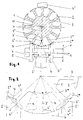
- armature of an electric machine is shown schematically as rotor 1 represented in section by a compensation plane.
- the invention can be used with any rotor that Places equidistantly arranged along a rotor circumference for Balancing due to material removal, e.g. profiled Shafts or rotors with radial extensions such as blades or wings; the invention is also applicable to Rotors with smooth peripheral surfaces in the compensation level or levels.
- the anchor has twelve pole pieces 2, which over Bridges 3 are connected to the anchor core. In the fields of between the pole pieces 2 and the webs 3 they are not copper wire windings of the armature shown.
- the Pole shoes 2 are the possible compensation points of the rotor.
- the Rotor 1 has an unbalance U to be compensated, which is in the central plane of the lower web 3 'in the drawing between the anchor core and pole piece 2 'lies and points downward.
- U unbalance
- the Bracket has two holding elements 4, 4 ', of which the lower holding element 4 the rotor 1 in one by the division of 12 holds defined stop position. Fixing the rotor in a rest position as well as its support instead done by facilities that are on balancing machines anyway available.
- the unbalance compensation takes place via material distances on the pole shoes 2 ' ' and 2 ' ' , which are arranged to the left and right of the pole piece 2 'in the drawing.
- two pole pieces can also be selected, which are separated by two or more pole pieces in between.
- the compensating tools 5, 5 ' can be, for example, disk cutters or grinding wheels which rotate about the spindle axis for material removal, for example by means of the driven tool spindle 6.
- the axial distance between the compensating tools 5, 5' is essentially determined by the center distance of the pole shoes 2 'selected for compensation. , 2 ' ' 1, this is the distance A.
- the machining profile should then be centered on the web axis at maximum immersion depth.
- the compensating tools each have the tip of an essentially triangular machining profile 7, 7 ', which is also selected with regard to the shape of the pole shoe, taking into account the web transition.
- the tip can also be flattened to remove as much material as possible near the surface.
- the triangular shape is chosen so that the central plane of the web cuts the angle at the machining triangle tip approximately in half, since a maximum radial machining depth can be achieved by the machining profile 7, 7 'tapering in the radial direction.
- the angle at the triangle tip is preferably in the range between 90 ° and 120 °, depending on the selection and design of the pole piece and the web transition. With the selected processing profile, as much material as possible should be removable near the surface.
- the tool spindle 6 is below in the example shown the rotor 1 attached with horizontal orientation; it can however, if necessary, the entire device for balancing any angle, e.g. pivoted by 90 ° about the rotor axis 10 to be ordered.
- the tool spindle 6 is in at least two Steplessly shiftable directions, namely tangential in direction H. to the rotor 1 and transverse to the rotor axis 10 and thus in the Horizontal and in the direction V, namely radial and thus in the vertical.
- the drive for moving the tool spindle 6 can be electrical, hydraulically or by other known drive mechanisms respectively.
- the Rotor 1 are moved; it can also be provided that Carry out tool spindle 6 and rotor 1 displacement movements.
- the tool spindle 6 is not displaced in the horizontal or tangential direction and is therefore in the symmetrical position shown with the tips of the compensation tools 5 ', 5' 'in each case at a distance A / 2 from the Middle plane of the web 3 '.
- the penetration depth of the compensating tools 5 ', 5' ' is determined by an evaluation device (not shown) on the basis of the unbalance U to be compensated and the specific conditions of the rotor 1 and machining profile of the compensating tools 5', 5 ' ' and the tool spindle 6 by the corresponding path in the vertical direction V shifted for material removal.
- the compensating tools 5 and 5 ' are indicated in three different positions; the unbroken lines show the axial and radial position of the compensation tools 5 and 5 ', with which an imbalance running in the center of the web 3' is compensated.
- An unbalance which runs in the direction of the dashed line a can be compensated for with the compensating tools 5, 5 'in the axially and radially displaced position a', a '' , in which the compensating tool 5 on the pole piece 2 '' of the web 3 '' when moving to a ', more material is removed than the compensating tool 5' when moving to position a '' on pole piece 2 '' ' .
- An unbalance that runs in the direction of the narrow dashed line b can be compensated for with the compensating tools 5, 5 'in the axially and radially displaced position b ' , b '' .
- both compensating tools 5, 5' are in engagement.
- the tip of the machining profile 7, 7 'of the deeper-penetrating compensation tool 5 or 5' lies at the maximum penetration depth in the central plane of the web 3 '' , 3 '''concerned .
- the angle at the tip of the machining profile 7, 7 ' is approximately 120 ° in the example shown and can be selected up to approximately 160 ° if necessary, and is therefore greater than the angle of the machining tip selected in the case of the 12-pitch rotor according to FIG. 1 of about 90 °.
- the angular range at the tip of the machining profile 7, 7 ' extends approximately symmetrically to the central plane of the web 3 '' , 3 ''' .
- the maximum tangential displacement of the compensation tools 5, 5 'in the position a ' , a ' or the position b ' , b ' corresponds to about 1/4 of the maximum penetration depth in the web direction in the example shown
- FIG. 1 An embodiment is not shown, in which a Rotor with 12 division, as shown in Fig. 1, instead only one pole piece two pole pieces between the pole pieces which are to be compensated.
- the rotor is in a position in which the central plane between two pole pieces facing downwards, fixable according to division.
- a divisional Angular range in which the unbalance to be compensated can lie, reached, i.e. in the case of a rotor with 12 compensation points an angular range of 30 ° between two adjacent webs.
- the invention also extends to arrangements in which the material decreases at immediately adjacent compensation points is made; however, in this case there is an unbalance compensation area given by a division only if one of the two compensation tools when hiking the determined Unbalance in an unbalance limit position in the central plane of a Stegs does the material removal alone while the other Compensation tool for this case of unbalance in the unbalance limit position in the middle plane not to interfere with the other Compensation point comes.
Landscapes
- Physics & Mathematics (AREA)
- General Physics & Mathematics (AREA)
- Manufacture Of Motors, Generators (AREA)
- Testing Of Balance (AREA)
Abstract
Description
- Fig. 1
- eine schematische Darstellung einer Vorrichtung zum Unwuchtausgleich an einem 12-poligen Rotor, bei der die auszugleichende Unwucht U in der Stegachse eines Polschuhs verläuft,
- Fig. 2
- eine Schemadarstellung bei einem Rotor mit acht möglichen Ausgleichsstellen

Claims (11)
- Verfahren zum Ausgleich einer ermittelten Unwucht an einem Rotor, der längs eines Rotorumfangs äquidistant angeordnete Stellen zum unwuchtausgleich durch Materialentfernung aufweist, bei dem einen festen gegenseitigen Abstand aufweisende Ausgleichswerkzeuge vorgesehen sind und bei dem die Ausgleichswerkzeuge quer zur Rotorachse durch eine aus der ermittelten Rotorunwucht resultierende Verschiebung zwischen Rotor und Ausgleichswerkzeugen in tangentialer Richtung positionierbar sind und zum Materialabtrag durch eine aus der ermittelten Rotorunwucht resultierende Verschiebung zumindest in radialer Richtung zwischen Rotor und Ausgleichswerkzeugen in den Rotor hinein bewegbar sind, dadurch gekennzeichnet, daß nur zwei Ausgleichswerkzeuge (5, 5') vorgesehen werden, daß die Ausgleichswerkzeuge (5, 5') beim Unwuchtausgleich stets gemeinsam in Eingriff mit dem Rotor (1) gebracht werden und daß mit den Ausgleichswerkzeugen (5, 5') Ausgleichskomponenten erzeugt werden, die im wesentlichen im Winkel eines ganzzahligen Vielfachen der Ausgleichsstellenteilung zueinander verlaufen.
- Verfahren zum Ausgleich einer ermittelten Unwucht an einem Rotor, der längs eines Rotorumfangs äquidistant angeordnete Stellen zum Unwuchtausgleich durch Materialentfernung aufweist, bei dem einen festen gegenseitigen Abstand aufweisende Ausgleichswerkzeuge vorgesehen sind und bei dem die Ausgleichswerkzeuge quer zur Rotorachse durch eine aus der ermittelten Rotorunwucht resultierende Verschiebung zwischen Rotor und Ausgleichswerkzeugen in tangentialer Richtung positionierbar sind und zum Materialabtrag durch eine aus der ermittelten Rotorunwucht resultierende Verschiebung zumindest in radialer Richtung zwischen Rotor und Ausgleichswerkzeugen in den Rotor hinein bewegbar sind, dadurch gekennzeichnet, daß nur zwei Ausgleichswerkzeuge (5, 5') vorgesehen werden, daß die Ausgleichswerkzeuge (5, 5') vorzugsweise gemeinsam in Eingriff mit dem Rotor (1) gebracht werden und daß mit den Ausgleichswerkzeugen (5, 5') Ausgleichskomponenten erzeugt werden, die etwa im Winkel der Ausgleichsstellenteilung zueinander verlaufen.
- Verfahren nach Anspruch 1 oder Anspruch 2, dadurch gekennzeichnet, daß der Rotor (1) zum Ausgleich in einer durch die Ausgleichsstellenteilung definierten Raststellung fixiert wird.
- Verfahren nach Anspruch 3, dadurch gekennzeichnet, daß eine zwischengeordnete Ausgleichsstelle zur Halterung des Rotors (1) herangezogen wird.
- Verfahren nach einem oder mehreren der vorhergehenden Ansprüche, dadurch gekennzeichnet, daß das Eintauchen der Ausgleichswerkzeuge (5, 5') in den Rotor (1) etwa mittig bezüglich der Ausgleichsstellen erfolgt.
- Verfahren nach einem oder mehreren der vorhergehenden Ansprüche, dadurch gekennzeichnet, daß mit den Ausgleichskomponenten ein in einem einer Ausgleichsstellenteilung entsprechenden Winkelbereich, der sich beiderseits einer möglichen Ausgleichsstelle oder beiderseits einer Mittelebene zwischen zwei möglichen oder benutzten Ausgleichsstellen erstreckt, liegender Unwuchtvektor ausgeglichen wird.
- Vorrichtung zum Ausgleich einer ermittelten Unwucht an einem Rotor, der längs eines Rotorumfangs äquidistant angeordnete Stellen zum Unwuchtausgleich durch Materialentfernung aufweist, mit einer Halterung für den Rotor und mit einen festen gegenseitigen Abstand aufweisenden Ausgleichswerkzeugen, bei der Rotor und/oder Ausgleichswerkzeuge in tangentialer und radialer Richtung verschiebbar sind, dadurch gekennzeichnet, daß nur zwei Ausgleichswerkzeuge (5, 5') vorgesehen sind, die in einem im wesentlichen einem ganzzahligen Vielfachen der Ausgleichsstellenteilung entsprechenden Abstand (A) zueinander angeordnet sind.
- Vorrichtung zum Ausgleich einer ermittelten Unwucht an einem Rotor, der längs eines Rotorumfangs äquidistant angeordnete Stellen zum Unwuchtausgleich durch Materialentfernung aufweist, mit einer Halterung für den Rotor und mit einen festen gegenseitigen Abstand aufweisenden Ausgleichswerkzeugen, bei der Rotor und/oder Ausgleichswerkzeuge in tangentialer und radialer Richtung verschiebbar sind, dadurch gekennzeichnet, daß nur zwei Ausgleichswerkzeuge (5, 5') vorgesehen sind, die in einem im wesentlichen der Ausgleichsstellenteilung entsprechenden Abstand zueinander angeordnet sind.
- Vorrichtung nach Anspruch 7 oder Anspruch 8, dadurch gekennzeichnet, daß die Halterung (4, 4') zur Fixierung des Rotors in einer teilungsgemäßen Raststellung vorgesehen ist.
- Vorrichtung nach einem oder mehreren der Ansprüche 7 bis 9, dadurch gekennzeichnet, daß ein Halteelement (4) der Halterung (4, 4') zumindest einer zwischen den Ausgleichsstellen zur Materialentfernung liegenden möglichen Ausgleichsstellezugeordnet ist.
- Vorrichtung nach einem oder mehreren der vorhergehenden Ansprüche, dadurch gekennzeichnet, daß das Halteelement (4, 4') als Gegenlager ausgebildet ist.
Applications Claiming Priority (2)
| Application Number | Priority Date | Filing Date | Title |
|---|---|---|---|
| DE19940469A DE19940469A1 (de) | 1999-08-26 | 1999-08-26 | Verfahren und Vorrichtung zum Unwuchtausgleich |
| DE19940469 | 1999-08-26 |
Publications (3)
| Publication Number | Publication Date |
|---|---|
| EP1079222A2 true EP1079222A2 (de) | 2001-02-28 |
| EP1079222A3 EP1079222A3 (de) | 2002-10-02 |
| EP1079222B1 EP1079222B1 (de) | 2010-05-12 |
Family
ID=7919665
Family Applications (1)
| Application Number | Title | Priority Date | Filing Date |
|---|---|---|---|
| EP00117790A Expired - Lifetime EP1079222B1 (de) | 1999-08-26 | 2000-08-18 | Verfahren und Vorrichtung zum Unwuchtsausgleich durch Materialentfernung |
Country Status (4)
| Country | Link |
|---|---|
| US (1) | US6520012B1 (de) |
| EP (1) | EP1079222B1 (de) |
| JP (1) | JP2001108560A (de) |
| DE (2) | DE19940469A1 (de) |
Cited By (1)
| Publication number | Priority date | Publication date | Assignee | Title |
|---|---|---|---|---|
| EP2048769A1 (de) * | 2003-08-18 | 2009-04-15 | VORWERK & CO. INTERHOLDING GmbH | Reluktanzmotor |
Families Citing this family (6)
| Publication number | Priority date | Publication date | Assignee | Title |
|---|---|---|---|---|
| US7534970B2 (en) * | 2006-06-15 | 2009-05-19 | Schenck Accurate, Inc. | Counterbalanced dispensing system |
| US8342804B2 (en) * | 2008-09-30 | 2013-01-01 | Pratt & Whitney Canada Corp. | Rotor disc and method of balancing |
| US9151298B2 (en) * | 2009-10-29 | 2015-10-06 | Koninklijke Philips N.V. | System and method for balancing an impeller assembly |
| JP5737015B2 (ja) * | 2011-07-06 | 2015-06-17 | 株式会社Ihi | 回転体のアンバランス修正加工方法 |
| DE102017125889A1 (de) * | 2017-11-06 | 2019-05-09 | Thyssenkrupp Ag | Verfahren und Vorrichtung zum Auswuchten |
| US12312091B2 (en) * | 2022-10-06 | 2025-05-27 | Archer Aviation Inc. | Systems and methods for improved gearboxes for evtol aircraft |
Family Cites Families (11)
| Publication number | Priority date | Publication date | Assignee | Title |
|---|---|---|---|---|
| DE1236829B (de) * | 1961-12-14 | 1967-03-16 | Schenck Gmbh Carl | Vorrichtung zum Unwuchtausgleich an rotierenden Koerpern |
| DE2243002B1 (de) * | 1972-09-01 | 1973-11-15 | Gebr. Hofmann Kg Maschinenfabrik, 6100 Darmstadt | Verfahren und Vorrichtung zum Aus wuchten von Rotoren |
| DE2638876C3 (de) * | 1976-08-28 | 1982-11-11 | Gebr. Hofmann Gmbh & Co Kg Maschinenfabrik, 6100 Darmstadt | Vorrichtung zum Auswuchten von Rotoren, insbesondere Elektromotorenankern |
| DE2946581C2 (de) * | 1979-11-19 | 1982-06-16 | Gebr. Hofmann Gmbh & Co Kg Maschinenfabrik, 6100 Darmstadt | Verfahren und Schaltungsanordnung zur Beseitigung von Unwuchten an Rotationskörpern |
| DE3005423A1 (de) * | 1980-02-14 | 1981-08-20 | Dionys Hofmann GmbH, Maschinenfabrik, 7470 Albstadt | Vorrichtung zum auswuchten von rotoren, insbesondere elektromotorenanker |
| DE3107539C2 (de) * | 1981-02-27 | 1986-07-10 | Gebr. Hofmann Gmbh & Co Kg Maschinenfabrik, 6100 Darmstadt | Verfahren und Vorrichtung zum Ausgleich einer Unwucht an einem Rotor |
| DE3638158A1 (de) * | 1986-11-08 | 1988-05-11 | Schenck Ag Carl | Unwuchtmessstation |
| US5199992A (en) * | 1990-03-01 | 1993-04-06 | Hines Industries, Inc. | Apparatus for the single station balancing and correction of rotating workpieces |
| JP2989065B2 (ja) * | 1992-02-04 | 1999-12-13 | 株式会社ミツバ | 回転体の不釣り合い修正装置 |
| DE4229521B4 (de) * | 1992-09-07 | 2004-10-21 | Schenck Rotec Gmbh | Verfahren zum Unwuchtausgleich eines Rotors |
| IT1285484B1 (it) * | 1996-10-08 | 1998-06-08 | Balance Systems Srl | Dispositivo di equilibratura di un rotore mediante asportazione di materiale |
-
1999
- 1999-08-26 DE DE19940469A patent/DE19940469A1/de not_active Withdrawn
-
2000
- 2000-08-18 EP EP00117790A patent/EP1079222B1/de not_active Expired - Lifetime
- 2000-08-18 DE DE50015924T patent/DE50015924D1/de not_active Expired - Lifetime
- 2000-08-21 US US09/642,368 patent/US6520012B1/en not_active Expired - Lifetime
- 2000-08-28 JP JP2000257785A patent/JP2001108560A/ja active Pending
Cited By (1)
| Publication number | Priority date | Publication date | Assignee | Title |
|---|---|---|---|---|
| EP2048769A1 (de) * | 2003-08-18 | 2009-04-15 | VORWERK & CO. INTERHOLDING GmbH | Reluktanzmotor |
Also Published As
| Publication number | Publication date |
|---|---|
| JP2001108560A (ja) | 2001-04-20 |
| EP1079222A3 (de) | 2002-10-02 |
| DE50015924D1 (de) | 2010-06-24 |
| EP1079222B1 (de) | 2010-05-12 |
| US6520012B1 (en) | 2003-02-18 |
| DE19940469A1 (de) | 2001-03-01 |
Similar Documents
| Publication | Publication Date | Title |
|---|---|---|
| DE2442139C2 (de) | ||
| DE102013223293A1 (de) | Honwerkzeug und Verfahren zum Bearbeiten mehrerer koaxialer Bohrungen | |
| DE2165497A1 (de) | Maschine zur automatischen, schnellen und genauen bearbeitung kleiner teile, auch komplizierter formgebung | |
| DE19821763B4 (de) | Vorschubeinrichtung für eine Industriemaschine und Industriemaschine, die diese verwendet | |
| WO2016177452A1 (de) | Werkzeugmaschine | |
| DE19619720A1 (de) | Mehrspindeldrehmaschine | |
| DE10261701A1 (de) | Automatischer Werkzeugwechsler für eine Werkzeugmaschine | |
| DE102009039346A1 (de) | Verfahren zur spanenden Drehbearbeitung und Drehbearbeitungsvorrichtung | |
| EP1079222A2 (de) | Verfahren und Vorrichtung zum Unwuchtsausgleich durch Materialentfernung | |
| EP2374574B1 (de) | Hochgeschwindigkeits-Honmaschine | |
| DE4029724C2 (de) | ||
| DE102019130076B4 (de) | Arbeitswerkzeugvorrichtung geeignet für eine Federherstellungsmaschine, Federherstellungsmaschine und Federherstellungsverfahren zum Formen einer Feder | |
| EP3311967A1 (de) | Holzbearbeitungsvorrichtung | |
| WO2011069719A1 (de) | Anordnung zum schleifen von elektroden und schleifscheibe | |
| DE102016110617A1 (de) | Verfahren zum Bearbeiten mehrerer Werkstücke auf einem drehbaren Werkstückträger sowie Werkstückträger und Bearbeitungsmaschine hierfür | |
| DE102005049530A1 (de) | Werkzeugmaschine | |
| DE3901888A1 (de) | Werkzeugbestueckte drehraeummaschine | |
| EP1283585A1 (de) | Vorrichtung zum Wickeln eines mehrpoligen Stators | |
| DE4229521B4 (de) | Verfahren zum Unwuchtausgleich eines Rotors | |
| DE1933775A1 (de) | Funkenerosionskopf | |
| DE19607883A1 (de) | Vertikal-Drehmaschine | |
| EP3325210B1 (de) | Andock-maschine | |
| EP3903979A1 (de) | Verfahren zum bearbeiten des kopfkreisdurchmessers und kombinationswerkzeug zum erzeugen eines zahnrads | |
| DE3036134A1 (de) | Verfahren und vorrichtung zum funkenerosionsbearbeiten von werkstuecken | |
| EP3200947B1 (de) | Verfahren zur fertigbearbeitung von lagerbohrungen in einem werkstück |
Legal Events
| Date | Code | Title | Description |
|---|---|---|---|
| PUAI | Public reference made under article 153(3) epc to a published international application that has entered the european phase |
Free format text: ORIGINAL CODE: 0009012 |
|
| AK | Designated contracting states |
Kind code of ref document: A2 Designated state(s): AT BE CH CY DE DK ES FI FR GB GR IE IT LI LU MC NL PT SE |
|
| AX | Request for extension of the european patent |
Free format text: AL;LT;LV;MK;RO;SI |
|
| PUAL | Search report despatched |
Free format text: ORIGINAL CODE: 0009013 |
|
| AK | Designated contracting states |
Kind code of ref document: A3 Designated state(s): AT BE CH CY DE DK ES FI FR GB GR IE IT LI LU MC NL PT SE |
|
| AX | Request for extension of the european patent |
Free format text: AL;LT;LV;MK;RO;SI |
|
| 17P | Request for examination filed |
Effective date: 20021116 |
|
| AKX | Designation fees paid |
Designated state(s): DE FR GB IT |
|
| 17Q | First examination report despatched |
Effective date: 20080624 |
|
| GRAP | Despatch of communication of intention to grant a patent |
Free format text: ORIGINAL CODE: EPIDOSNIGR1 |
|
| GRAS | Grant fee paid |
Free format text: ORIGINAL CODE: EPIDOSNIGR3 |
|
| GRAA | (expected) grant |
Free format text: ORIGINAL CODE: 0009210 |
|
| AK | Designated contracting states |
Kind code of ref document: B1 Designated state(s): DE FR GB IT |
|
| REG | Reference to a national code |
Ref country code: GB Ref legal event code: FG4D Free format text: NOT ENGLISH |
|
| REF | Corresponds to: |
Ref document number: 50015924 Country of ref document: DE Date of ref document: 20100624 Kind code of ref document: P |
|
| PLBE | No opposition filed within time limit |
Free format text: ORIGINAL CODE: 0009261 |
|
| STAA | Information on the status of an ep patent application or granted ep patent |
Free format text: STATUS: NO OPPOSITION FILED WITHIN TIME LIMIT |
|
| 26N | No opposition filed |
Effective date: 20110215 |
|
| REG | Reference to a national code |
Ref country code: DE Ref legal event code: R097 Ref document number: 50015924 Country of ref document: DE Effective date: 20110214 |
|
| REG | Reference to a national code |
Ref country code: FR Ref legal event code: PLFP Year of fee payment: 16 |
|
| PGFP | Annual fee paid to national office [announced via postgrant information from national office to epo] |
Ref country code: GB Payment date: 20150824 Year of fee payment: 16 |
|
| PGFP | Annual fee paid to national office [announced via postgrant information from national office to epo] |
Ref country code: FR Payment date: 20150824 Year of fee payment: 16 |
|
| PGFP | Annual fee paid to national office [announced via postgrant information from national office to epo] |
Ref country code: IT Payment date: 20150827 Year of fee payment: 16 |
|
| PGFP | Annual fee paid to national office [announced via postgrant information from national office to epo] |
Ref country code: DE Payment date: 20150930 Year of fee payment: 16 |
|
| REG | Reference to a national code |
Ref country code: DE Ref legal event code: R119 Ref document number: 50015924 Country of ref document: DE |
|
| GBPC | Gb: european patent ceased through non-payment of renewal fee |
Effective date: 20160818 |
|
| REG | Reference to a national code |
Ref country code: FR Ref legal event code: ST Effective date: 20170428 |
|
| PG25 | Lapsed in a contracting state [announced via postgrant information from national office to epo] |
Ref country code: FR Free format text: LAPSE BECAUSE OF NON-PAYMENT OF DUE FEES Effective date: 20160831 Ref country code: DE Free format text: LAPSE BECAUSE OF NON-PAYMENT OF DUE FEES Effective date: 20170301 Ref country code: GB Free format text: LAPSE BECAUSE OF NON-PAYMENT OF DUE FEES Effective date: 20160818 |
|
| PG25 | Lapsed in a contracting state [announced via postgrant information from national office to epo] |
Ref country code: IT Free format text: LAPSE BECAUSE OF NON-PAYMENT OF DUE FEES Effective date: 20160818 |