EP1079236A2 - Assemblage d'aimants supraconducteurs comportant un "shim Z2" - Google Patents
Assemblage d'aimants supraconducteurs comportant un "shim Z2" Download PDFInfo
- Publication number
- EP1079236A2 EP1079236A2 EP00117689A EP00117689A EP1079236A2 EP 1079236 A2 EP1079236 A2 EP 1079236A2 EP 00117689 A EP00117689 A EP 00117689A EP 00117689 A EP00117689 A EP 00117689A EP 1079236 A2 EP1079236 A2 EP 1079236A2
- Authority
- EP
- European Patent Office
- Prior art keywords
- shim coil
- shim
- coil set
- magnet arrangement
- arrangement according
- Prior art date
- Legal status (The legal status is an assumption and is not a legal conclusion. Google has not performed a legal analysis and makes no representation as to the accuracy of the status listed.)
- Granted
Links
Images


Classifications
-
- G—PHYSICS
- G01—MEASURING; TESTING
- G01R—MEASURING ELECTRIC VARIABLES; MEASURING MAGNETIC VARIABLES
- G01R33/00—Arrangements or instruments for measuring magnetic variables
- G01R33/20—Arrangements or instruments for measuring magnetic variables involving magnetic resonance
- G01R33/28—Details of apparatus provided for in groups G01R33/44 - G01R33/64
- G01R33/42—Screening
- G01R33/421—Screening of main or gradient magnetic field
-
- G—PHYSICS
- G01—MEASURING; TESTING
- G01R—MEASURING ELECTRIC VARIABLES; MEASURING MAGNETIC VARIABLES
- G01R33/00—Arrangements or instruments for measuring magnetic variables
- G01R33/20—Arrangements or instruments for measuring magnetic variables involving magnetic resonance
- G01R33/28—Details of apparatus provided for in groups G01R33/44 - G01R33/64
- G01R33/38—Systems for generation, homogenisation or stabilisation of the main or gradient magnetic field
- G01R33/381—Systems for generation, homogenisation or stabilisation of the main or gradient magnetic field using electromagnets
- G01R33/3815—Systems for generation, homogenisation or stabilisation of the main or gradient magnetic field using electromagnets with superconducting coils, e.g. power supply therefor
-
- G—PHYSICS
- G01—MEASURING; TESTING
- G01R—MEASURING ELECTRIC VARIABLES; MEASURING MAGNETIC VARIABLES
- G01R33/00—Arrangements or instruments for measuring magnetic variables
- G01R33/20—Arrangements or instruments for measuring magnetic variables involving magnetic resonance
- G01R33/28—Details of apparatus provided for in groups G01R33/44 - G01R33/64
- G01R33/38—Systems for generation, homogenisation or stabilisation of the main or gradient magnetic field
- G01R33/387—Compensation of inhomogeneities
- G01R33/3875—Compensation of inhomogeneities using correction coil assemblies, e.g. active shimming
Definitions
- Such an actively shielded superconducting magnet arrangement with a Z 2 shim device comprises, for example, the NMR Magnet System 500 SB UltraShield TM sold by Bruker Magnetics in accordance with the company prospectus dated May 15, 1999.
- An actively shielded superconducting magnet arrangement without a Z 2 shim is known, for example, from EP 0 144 171 A1.
- the magnetic field in the Sample volumes have good homogeneity.
- the geometric Arrangement of the field-generating solenoids can reduce the basic homogeneity of the superconducting magnets can be optimized.
- the basic homogeneity is like high-resolution nuclear magnetic resonance spectroscopy of the magnet mostly insufficient because, for example, deviations from Design due to production inaccuracies.
- the magnet system compensates for residual inhomogeneities in the magnet equipped with autonomous superconducting coils, which field inhomogeneities with a certain geometric symmetry in the sample volume can compensate for so-called shims.
- Z 2 shim An example of such a shim is the Z 2 shim, which generates a field whose strength varies along the magnetic axis z in proportion to z 2 .
- a problem with known Z 2 shim devices according to the prior art is that with large magnets the shim must be wound inside the magnet coils, since it would be too weak on the outside. This means that space for magnet windings is lost, which makes the magnet more expensive and increases the stray field. In magnetic systems with active stray field compensation, this has the consequence that the stray field shielding must be reinforced.
- An optimization of the Z 2 shim can be achieved by reducing the space requirement of the Z 2 shim coils, which are located radially in the area of the coil package of the magnet. Without weakening the shim efficiency, this is only possible by distributing the shim coils over several radii. This creates new problems, particularly in connection with the disturbance of the shim due to fluctuating external magnetic fields.
- the object of the present invention is a Magnet arrangement of the type described in the introduction with the simplest possible To optimize means so that the problems described above do not occur.
- the magnet's sensitivity to interference is also reduced.
- FIG. 2 A conventional Z 2 shim according to the prior art is shown schematically in FIG. 2.
- ⁇ H 0 compensation the pair of coils S 2 'will normally couple more strongly with the magnet than S 1 '. This coupling is canceled by a pair of coils S 3 ', which greatly reduces the shim efficiency c 2 .
- the shim is divided into a shim coil set S i decoupled from the magnet with partial coils S 1 and S 2 to generate the gradient field c 2 * z 2 + ⁇ H 0 and in a likewise decoupled from the magnet shim coil set S a with the Tellspule S 3, wherein the impurity AH cancels 0th
- the gradient-generating shim coil set S i must be located radially further inward than the shim coil set S a to suppress ⁇ H 0 .
- this new shim arrangement is that with the suppression of ⁇ H 0 by a radially outer shim coil set, the shim strength c 2 of the radially inner shim coil set is only slightly weakened. As a result, fewer turns are required in the radially inner shim coil set and the magnet can be made more compact if the radially inner shim coil set is in a place where magnetic windings would otherwise be accommodated.
- both the radially inner shim coil set and the magnet arrangement can radially outer shim coil set shorted for superconducting become. That the inner and outer shim coil set short-circuited separately has advantages for the production of the Magnet arrangement because bridging the radius difference between the radially inner and outer shim coil set not necessarily superconducting have to be. In addition, there is the possibility of using the two shim parts operate different currents.
- the magnet arrangement is part of an apparatus for high-resolution magnetic resonance spectroscopy.
- the advantages of the present invention pay off particularly in systems such as high-resolution magnetic resonance spectrometers, since these magnetic systems are already more voluminous than others because of the high homogeneity requirements, and therefore a gain in compactness of the Z 2 shim is particularly important.
- a further development of this embodiment is advantageous, in which the Magnetic resonance apparatus a device for field lock of the im Has working volume generated magnetic field, the radially inner and the radially outer shim coil set largely from the coils of the device Feldlock are decoupled.
- An active field lock with a coil for compensation of temporal field fluctuations in the sample volume belongs to Standard equipment of high-resolution magnetic resonance systems.
- the Decoupling the field lock coil from the radially inner and outer shim coil set causes that no current is induced in the shim when the lock coil is actuated can. On the one hand, the field homogeneity is maintained and on the other hand, the The effect of the field lock coil is not impaired.
- the magnetic resonance apparatus Has sweep coils, the radially inner shim coil set and the radial outer shim coil set are largely decoupled from the sweep coils.
- the Decoupling susceptible sweep coils from the radially inner and outer Shim coil set means that when you operate the sweep coils in the shim, none Current can be induced. On the one hand, the field homogeneity remains during the field sweep is obtained and on the other hand the effect of the sweep coils not affected.
- the radially inner and / or the radial outer shim coil set made up of several partial coils.
- the advantage of this Arrangement is that with more coils per shim coil set Degrees of freedom to optimize shim strength and decoupling from the magnet available.
- This arrangement gives the maximum shim strength c 2 of a shim coil set on a certain radius for a certain number of ampere turns.
- the radially outer shim coil set advantageously comprises only partial coils of the same polarity.
- the efficiency of the outer shim coil set for generating - ⁇ H 0 would namely be reduced if partial coils of different polarity were used, for example for decoupling from the actively shielded magnet.
- An embodiment of the invention is also preferred in which the radially outer shim coil set is arranged in the immediate radial vicinity of the radially outer field coil system of the actively shielded magnet. This enables a simple, efficient decoupling of the outer shim coil set from the actively shielded magnet without using partial coils of different polarity, that is to say without weakening the H 0 efficiency.
- An embodiment is also advantageous in which the coils of the radially inner one and / or the radially outer shim coil set are distributed over several radii. This gives more degrees of freedom to the design of the shim, in particular, there are better possibilities for decoupling the Shim coil sets from the actively shielded magnet.
- the reduction of the dipole moment D i of the inner shim coil set is a possible way.
- the inner shim coil set is decoupled from external homogeneous interference sources and does not react with a current change ⁇ I 2 , which would lead to the disturbance of the field homogeneity in the working volume to be avoided.
- the dipole moment D i is ⁇ 0.
- the inductive coupling is at least between the radially inner and the radially outer shim coil set approximately 0. This on the one hand avoids that a possible Response of the radially outer shim coil set to an external fault on the can be transmitted internally and thus to a homogeneity of the field in the field Work volume would lead. On the other hand, it allows decoupling between the shim coil sets that both can be loaded individually without to influence each other.
- the radially outer shim coil set is designed as a Z 0 shim.
- the outer shim coil set thus creates a homogeneous field in the working volume and is decoupled from the other coils of the magnet arrangement.
- this advantage can only be exploited with appropriate wiring.
- Another preferred embodiment is characterized in that the radially inner shim coil set is electrically connected in series with the radial outer shim coil set, and that at least two superconducting switches are provided with which the two shim coil sets are separated from each other can be short-circuited superconducting.
- the series connection of both Shim coil sets allow them to be charged simultaneously with a charging current can be.
- Another variant provides that a superconducting switch in parallel is switched to one of the two shim coil sets.
- the two are connected in series Shim coil sets are resistive and a superconducting switch is parallel to each switched one of the two shim coil sets.
- a current limiter is preferably provided, through which the differential current flows between the radially inner and the radially outer shim coil set. With the current limiter can cause an undesirable differential current between radial inner and outer shim coil set are removed.
- An advantageous development of the invention is characterized in that the superconducting switch of the two shim coil sets each have a heating device have with a heater of another superconducting switch of the two shim coil sets is electrically connected in series.
- the simultaneous Loading the inner and outer shim coil set requires that both switches are simultaneously heated (open, i.e. resistive). In the arrangement according to the above Further training is this condition thanks to the special heater wiring automatically always fulfilled.
- the heating devices of the superconducting switches of the two shim coil sets can preferably be heated separately.
- the fact that each switch can be heated separately (open, i.e. resistive) enables autonomous charging of the inner and / or outer shim coil set (eg the outer one as a Z 0 shim).
- the arrangement comprises a radially inner shim coil set S i consisting of a partial coil S 1 with negative polarity and a partial coil S 1 axially encompassing the partial coil S 1 with positive polarity and a radially outer shim coil set S a with the partial coil S 3 integrated into a superconducting magnet arrangement consisting of a magnet M 1 with several sections and an active stray field shielding coil M 2 .
- FIG. 2 shows a diagram of a superconducting magnet arrangement according to the prior art consisting of a magnet M 1 with several sections and an active stray field shielding coil M 2 , and a Z 2 shim arrangement with the coils S 1 ', S 2 ' and S 3 ' .
- the y n correspond to the gradients H n [G / cm n ] of a current-carrying cylinder surface with a radius of 1 cm and a current density of 1 A / cm.
- the extreme of y 2 at s ⁇ 0.5 means that a coil of a given radius and current density most efficiently generates an H 2 gradient at a length of L ⁇ R.
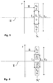
- FIG. 5 A diagram corresponding to the arrangement according to FIG. 1 of a three-coil design of the radially inner shim coil set S i with the partial coils S 1 and S 2 at a radius R is shown in FIG. 5.
- the partial coil S 1 has an axial length L 1
- FIG. 6 shows a schematic of an embodiment of the radially inner shim coil set S i ′′ of a Z 2 shim according to the invention with an additional notch in the middle coil section S 1 ′′ for suppressing an H 4 Contamination "of the Shimfeld.
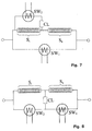
- FIG. 7 shows a wiring diagram of the radially inner and radially outer shim coil sets S i and S a of a Z 2 shim according to the invention with superconducting series connection of the two shim coil sets.
- a first superconducting switch SW 1 bridges the entire shim
- a second superconducting switch SW 2 only bridges the radially inner shim coil set S i .
- the differential current between the two shim coil sets can be limited by a current limiter CL.
- the two shim coil sets S i and S a are also superconductively connected in series.
- the first superconducting switch SW 1 bridges the radially outer shim coil set S a
- the second superconducting switch SW 2 bridges the radially inner shim coil set S i .
- the differential current between the two shim coil sets can also be limited here by a current limiter CL.
- FIG. 9 shows a wiring diagram of the radially inner and radially outer shim coil set S i and S a of a Z 2 shim according to the invention with a resistive series connection (represented by the equivalent resistance r) of the two shim coil sets.
- the first superconducting switch SW 1 bridges the radially outer shim coil set S a
- the second superconducting switch SW 2 bridges the radially inner shim coil set S i .
- FIG. 10 the diagram of a cylindrical current coating j is included Radius R and length L shown symmetrically to the magnetic center MZ.
- the magnetic resonance methods require a high degree of homogeneity of the Magnetic field in the sample volume.
- a good one Basic homogeneity of the field must be achieved, on the other hand production-related deviations from the intended basic homogeneity be remedied by further measures.
- the low-order coefficients must be brought to zero in the design of the magnet.
- the coefficients H n of the field development are also called gradients.
- the Z 2 shim eliminates an undesirable H 2 gradient of the magnet, ie the field profile of this shim on the magnet axis is proportional to z 2 .
- the efficiency or strength c 2 of the Z 2 shim is the H 2 gradient that is generated per ampere.
- H 0 jy 0 ( s )
- H 2 j R 2 y 2 ( s )
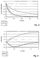
- H 4th j R 4th y 4th ( s ) with functions y 0 (s) , y 2 (s) and y 4 (s) of the dimension [G ⁇ cm / A], which are shown in FIG. 4.
- R is the cylinder radius in [cm]. What is important is the fact that the efficiency of the gradient H n is inversely proportional to the nth power of the radius R. (Fig.
- the dependence of the gradient efficiency of a coil on its radius has the consequence that a Z 2 shim must be attached to a small radius if a high shim efficiency is to be achieved.
- the shim In addition to the strength c 2 of the Z 2 shim to be achieved, other criteria must also be observed when designing shims for superconducting magnet systems, in particular the shim must not have a homogeneous field component ⁇ H 0 and it must be inductively decoupled from the superconducting magnet. Otherwise, undesirable effects would occur, such as a field shift during shimming, shim current changes due to a possible magnetic drift or high induced currents in the shim when the magnet quenched.
- the resulting shim efficiency can be greatly increased. Because of the quadratic radius dependence of the H 2 gradient of a coil, the radially outer shim coil set makes at most a small contribution to the overall shim efficiency.
- the coil arrangement according to the invention of a Z 2 shim pays off in particular when used in actively stray-field-shielded superconducting magnet systems, because an expansion of the main coil of the magnet by integrated shim coils must be avoided due to the associated increase in stray field and particularly advantageous solutions for the coil arrangement according to the invention Z 2 shims result. For this reason, the invention is limited to the description of a Z 2 shim distributed in a radially inner and a radially outer shim coil set in an actively shielded magnet.
- a coil arrangement according to the invention of a Z 2 shim is shown in FIG. 1 together with a magnet with active stray field compensation.
- the desired behavior of the radially outer shim coil set with respect to these coils will result from the large radius of the shim coils without further design measures.
- the basic configuration of the Z 2 shim arrangement according to the invention with separate superconducting short-circuit of the radially inner and outer shim coil set results in a general improvement in the susceptibility of the magnet system to the homogeneous without further design measures Field share of external field fluctuations.
- each of the two superconductingly closed current paths must have its own superconducting switch, which is opened to charge the associated current path.
- both switches When loading the overall shim, both switches must be open simultaneously. This is automatically achieved if the switch heaters are connected in series. In certain situations, such as using the radially outer shim coil set as a Z 0 shim, it is necessary that the individual switches can also be opened individually.
Landscapes
- Physics & Mathematics (AREA)
- Condensed Matter Physics & Semiconductors (AREA)
- General Physics & Mathematics (AREA)
- Electromagnetism (AREA)
- Health & Medical Sciences (AREA)
- Epidemiology (AREA)
- Magnetic Resonance Imaging Apparatus (AREA)
Applications Claiming Priority (2)
| Application Number | Priority Date | Filing Date | Title |
|---|---|---|---|
| DE19940694 | 1999-08-27 | ||
| DE19940694A DE19940694C1 (de) | 1999-08-27 | 1999-08-27 | Aktiv abgeschirmte supraleitende Magnetanordnung mit Z·2·-Shim |
Publications (3)
| Publication Number | Publication Date |
|---|---|
| EP1079236A2 true EP1079236A2 (fr) | 2001-02-28 |
| EP1079236A3 EP1079236A3 (fr) | 2003-03-19 |
| EP1079236B1 EP1079236B1 (fr) | 2006-09-06 |
Family
ID=7919811
Family Applications (1)
| Application Number | Title | Priority Date | Filing Date |
|---|---|---|---|
| EP00117689A Expired - Lifetime EP1079236B1 (fr) | 1999-08-27 | 2000-08-17 | Assemblage d'aimants supraconducteurs comportant un "shim Z2" |
Country Status (4)
| Country | Link |
|---|---|
| US (1) | US6265960B1 (fr) |
| EP (1) | EP1079236B1 (fr) |
| JP (1) | JP3350027B2 (fr) |
| DE (2) | DE19940694C1 (fr) |
Cited By (2)
| Publication number | Priority date | Publication date | Assignee | Title |
|---|---|---|---|---|
| EP1376147A3 (fr) * | 2002-06-22 | 2005-01-05 | Bruker BioSpin AG | Assemblage d'aimants supraconducteurs blindé activement avec des moyens supplémentaires de compensation des champs de fuite |
| EP1612576A1 (fr) * | 2004-06-28 | 2006-01-04 | Hitachi, Ltd. | Bobines de shim pour la RMN |
Families Citing this family (32)
| Publication number | Priority date | Publication date | Assignee | Title |
|---|---|---|---|---|
| DE10041672C2 (de) * | 2000-08-24 | 2002-07-11 | Bruker Ag Faellanden | Magnetanordnung mit einem zusätzlichen stromführenden Spulensystem und Verfahren zu deren Dimensionierung |
| DE10060284C2 (de) * | 2000-12-05 | 2003-07-17 | Bruker Biospin Ag Faellanden | Magnetanordnung mit einem aktiv abgeschirmten supraleitenden Magnetspulensytem und einem zusätzlichen Strompfad zur Streufeldunterdrückung im Quenchfall |
| US6777938B2 (en) * | 2001-11-15 | 2004-08-17 | Bruker Biospin Gmbh | NMR magnet coil system with separate superconducting short-circuited regions for drift compensation as well as method for operation thereof |
| DE10227876B4 (de) * | 2002-06-22 | 2006-11-09 | Bruker Biospin Ag | Aktiv abgeschirmte, supraleitende Magnetanordnung mit verbesserter Streufeldkompensation |
| JP3845048B2 (ja) * | 2002-08-27 | 2006-11-15 | ジーイー・メディカル・システムズ・グローバル・テクノロジー・カンパニー・エルエルシー | 磁気共鳴撮影装置 |
| US20040095139A1 (en) * | 2002-11-19 | 2004-05-20 | Brown Mark Allen | Magnetic resonance spectroscopy |
| JP2004325251A (ja) * | 2003-04-24 | 2004-11-18 | Hitachi Ltd | 均一磁場発生装置およびそれを用いた核磁気共鳴装置 |
| US7230426B2 (en) * | 2003-06-20 | 2007-06-12 | General Electric Company | Split-shield gradient coil with improved fringe-field |
| DE10331610B3 (de) * | 2003-07-12 | 2005-03-24 | Bruker Biospin Gmbh | Verfahren zur Homogenisierung eines supraleitenden NMR-Magneten |
| DE10344983B3 (de) * | 2003-09-27 | 2005-08-11 | Bruker Biospin Gmbh | Verfahren zum Laden eines aktiv abgeschirmten supraleitenden NMR-Magneten |
| US6965236B2 (en) * | 2003-11-20 | 2005-11-15 | Ge Medical Systems Global Technology Co., Llc | MRI system utilizing supplemental static field-shaping coils |
| US6977571B1 (en) | 2004-11-08 | 2005-12-20 | General Electric Company | Secondary coil circuit for use with a multi-section protected superconductive magnet coil circuit |
| KR100635885B1 (ko) * | 2004-12-14 | 2006-10-18 | 한국기초과학지원연구원 | 고균등 고자장 발생용 초전도 자석의 설계방법 |
| WO2006097864A1 (fr) * | 2005-03-17 | 2006-09-21 | Koninklijke Philips Electronics, N.V. | Bobines de compensation a energie minimum pour resonance magnetique |
| US7098663B1 (en) * | 2005-03-18 | 2006-08-29 | Timothy James Hollis | Systems, methods and apparatus of an actively shielded superconducting magnet drift compensation coil |
| DE102005040374B4 (de) * | 2005-08-25 | 2008-10-02 | Bruker Biospin Ag | Supraleitende Magnetanordnung mit kontaktierbaren Widerstandselementen |
| US7570141B2 (en) * | 2005-12-05 | 2009-08-04 | General Electric Company | Method of designing a shim coil to reduce field settling time |
| US7642779B2 (en) * | 2007-03-22 | 2010-01-05 | Kabushiki Kaisha Toshiba | MRI RF coil configured to decouple coil elements and MRI apparatus employing the same |
| DE102007021463B4 (de) * | 2007-05-08 | 2012-05-16 | Bruker Biospin Ag | Supraleitende Magnetanordnung mit hysteresenfreier Feldspule |
| JP4542573B2 (ja) * | 2007-08-07 | 2010-09-15 | 株式会社日立製作所 | アクティブシールド型の超電導電磁石装置および磁気共鳴イメージング装置 |
| US20090103217A1 (en) * | 2007-10-17 | 2009-04-23 | General Electric Company | System and apparatus for limiting current in a superconducting coil |
| US7427908B1 (en) * | 2007-12-21 | 2008-09-23 | Florida State University Research Foundation | Magnetic shimming configuration with optimized turn geometry and electrical circuitry |
| DE102008020107B4 (de) | 2008-04-22 | 2011-08-25 | Bruker BioSpin GmbH, 76287 | Kompakte supraleitende Magnetanordnung mit aktiver Abschirmung, wobei die Abschirmspule zur Feldformung eingesetzt wird |
| JP5534713B2 (ja) | 2009-05-20 | 2014-07-02 | 三菱電機株式会社 | 超電導マグネット |
| DE102009045373B4 (de) * | 2009-10-06 | 2011-12-08 | Bruker Biospin Gmbh | Kompakte supraleitende Magnetanordnung mit aktiver Abschirmung, wobei die Abschirmspule das Feldmaximum der Hauptfeldspule dämpft |
| DE102011080275B4 (de) * | 2011-08-02 | 2018-10-25 | Siemens Healthcare Gmbh | Lokalspule, insbesondere Halsspule, mit mehreren separat schaltbaren Lokalspulen- Shimspulen |
| DE102011087485B3 (de) * | 2011-11-30 | 2013-05-29 | Siemens Aktiengesellschaft | Magnetresonanztomographie-Anlage, Verfahren zum Ausgleichen einer Feldinhomogenität in der Anlage und Shimspulenanordnung |
| CN104730475B (zh) * | 2013-12-23 | 2020-07-07 | Ge医疗系统环球技术有限公司 | 一种磁场调整系统和方法以及磁共振成像系统 |
| EP3396686B1 (fr) * | 2017-04-27 | 2022-03-30 | Japan Superconductor Technology, Inc. | Dispositif d'aimant supraconducteur |
| WO2019067905A1 (fr) * | 2017-09-28 | 2019-04-04 | Cedars-Sinai Medical Center | Bobines de résonance magnétique pour imagerie et homogénéisation b0 simultanées |
| CN110927642B (zh) * | 2019-12-05 | 2021-09-10 | 湖南迈太科医疗科技有限公司 | 磁共振成像的匀场控制方法、装置和系统 |
| GB2608409B (en) * | 2021-06-30 | 2026-03-18 | Oxford Nanoscience Ltd | Magnet System |
Family Cites Families (4)
| Publication number | Priority date | Publication date | Assignee | Title |
|---|---|---|---|---|
| US4180769A (en) * | 1978-02-21 | 1979-12-25 | Varian Associates, Inc. | Superconducting solenoid with compensation for axial gradients |
| US4587504A (en) * | 1983-11-11 | 1986-05-06 | Oxford Magnet Technology Limited | Magnet assembly for use in NMR apparatus |
| JPH0779942A (ja) * | 1993-09-13 | 1995-03-28 | Toshiba Corp | 磁気共鳴イメージング装置 |
| DE19525322C1 (de) * | 1995-07-12 | 1997-02-06 | Bruker Analytische Messtechnik | Therapietomograph mit Homogenisierungseinrichtung |
-
1999
- 1999-08-27 DE DE19940694A patent/DE19940694C1/de not_active Expired - Fee Related
-
2000
- 2000-08-17 EP EP00117689A patent/EP1079236B1/fr not_active Expired - Lifetime
- 2000-08-17 DE DE50013424T patent/DE50013424D1/de not_active Expired - Lifetime
- 2000-08-23 US US09/643,933 patent/US6265960B1/en not_active Expired - Lifetime
- 2000-08-24 JP JP2000253825A patent/JP3350027B2/ja not_active Expired - Lifetime
Cited By (3)
| Publication number | Priority date | Publication date | Assignee | Title |
|---|---|---|---|---|
| EP1376147A3 (fr) * | 2002-06-22 | 2005-01-05 | Bruker BioSpin AG | Assemblage d'aimants supraconducteurs blindé activement avec des moyens supplémentaires de compensation des champs de fuite |
| EP1612576A1 (fr) * | 2004-06-28 | 2006-01-04 | Hitachi, Ltd. | Bobines de shim pour la RMN |
| US7157912B2 (en) | 2004-06-28 | 2007-01-02 | Hitachi, Ltd. | Apparatus for generating homogeneous magnetic field |
Also Published As
| Publication number | Publication date |
|---|---|
| EP1079236A3 (fr) | 2003-03-19 |
| JP2001099904A (ja) | 2001-04-13 |
| EP1079236B1 (fr) | 2006-09-06 |
| JP3350027B2 (ja) | 2002-11-25 |
| DE50013424D1 (de) | 2006-10-19 |
| DE19940694C1 (de) | 2001-07-26 |
| US6265960B1 (en) | 2001-07-24 |
Similar Documents
| Publication | Publication Date | Title |
|---|---|---|
| DE19940694C1 (de) | Aktiv abgeschirmte supraleitende Magnetanordnung mit Z·2·-Shim | |
| EP1065512B1 (fr) | Arrangement d'aimants supraconducteurs activement blindés avec compensation de perturbations du champ | |
| DE4101481C2 (de) | Anordnung zum Kompensieren externer Magnetfeldstörungen bei einem Kernresonanzspektrometer mit supraleitender Magnetspule | |
| DE102009045774B4 (de) | Kompakte supraleitende Magnetanordnung mit aktiver Abschirmung, wobei die Abschirmspule zur Feldformung eingesetzt wird | |
| EP0257371B1 (fr) | Dispositif pour compenser des perturbations de champs variables en temps dans des champs magnétiques | |
| EP2146215B1 (fr) | Appareil d'exécution de mesures DNP-RMN doté d'un agencement de compensation et procédé de conception de l'agencement de compensation | |
| EP0945736A2 (fr) | Magnétomètre | |
| DE19930404C2 (de) | Aktiv abgeschirmte supraleitende Magnetanordnung mit verbesserter Feldstörungskompensation | |
| DE3937150C2 (fr) | ||
| DE19540746A1 (de) | Magnetresonanz-Abbildungssystem mit modularen Ganzkörper-Gradientenspulen | |
| DE69321082T2 (de) | Kernspinresonanzapparat mit einem supraleitenden Magneten | |
| DE102009045373B4 (de) | Kompakte supraleitende Magnetanordnung mit aktiver Abschirmung, wobei die Abschirmspule das Feldmaximum der Hauptfeldspule dämpft | |
| DE19829298C2 (de) | Gradientenspulensystem für ein Kernspintomographiegerät | |
| DE4142263A1 (de) | Gradientenspulensystem | |
| DE19527020C1 (de) | Tesserale Gradientenspule für Kernspintomographiegeräte | |
| DE19821739C1 (de) | Mobiles Kernspinresonanzgerät | |
| DE10041683C2 (de) | Supraleitende Shimvorrichtung in einer supraleitenden Magnetanordnung und Verfahren zu deren Dimensionierung | |
| DE3800908A1 (de) | Ein kompakter quergradienten-magnetspulenaufbau fuer eine magnetische resonanzspektroskopie-anlage | |
| DE10227877B4 (de) | Aktiv abgeschirmte, supraleitende Magnetanordnung mit einer Vorrichtung zur zusätzlichen Streufeldoptimierung | |
| DE60308122T2 (de) | Gradientenspulenstruktur für Kernspintomographie | |
| DE3725718A1 (de) | Probenkopf fuer nmr-spektrometer | |
| EP1229340B1 (fr) | Agencement d'aimants avec un système de bobines supraconductrices et un dispositif d'ajustage du champ magnétique pour la spectroscopie par résonance magnétique à haute résolution | |
| EP0177869B1 (fr) | Aménagement d'un aimant avec un dispositif d'écran pour une installation de tomographie de spin nucléaire | |
| DE10041672C2 (de) | Magnetanordnung mit einem zusätzlichen stromführenden Spulensystem und Verfahren zu deren Dimensionierung | |
| DE3534383C2 (fr) |
Legal Events
| Date | Code | Title | Description |
|---|---|---|---|
| PUAI | Public reference made under article 153(3) epc to a published international application that has entered the european phase |
Free format text: ORIGINAL CODE: 0009012 |
|
| AK | Designated contracting states |
Kind code of ref document: A2 Designated state(s): AT BE CH CY DE DK ES FI FR GB GR IE IT LI LU MC NL PT SE |
|
| AX | Request for extension of the european patent |
Free format text: AL;LT;LV;MK;RO;SI |
|
| RAP1 | Party data changed (applicant data changed or rights of an application transferred) |
Owner name: BRUKER BIOSPIN AG |
|
| PUAL | Search report despatched |
Free format text: ORIGINAL CODE: 0009013 |
|
| AK | Designated contracting states |
Kind code of ref document: A3 Designated state(s): AT BE CH CY DE DK ES FI FR GB GR IE IT LI LU MC NL PT SE |
|
| AX | Request for extension of the european patent |
Extension state: AL LT LV MK RO SI |
|
| 17P | Request for examination filed |
Effective date: 20030214 |
|
| AKX | Designation fees paid |
Designated state(s): CH DE FR GB LI |
|
| GRAP | Despatch of communication of intention to grant a patent |
Free format text: ORIGINAL CODE: EPIDOSNIGR1 |
|
| GRAS | Grant fee paid |
Free format text: ORIGINAL CODE: EPIDOSNIGR3 |
|
| GRAA | (expected) grant |
Free format text: ORIGINAL CODE: 0009210 |
|
| AK | Designated contracting states |
Kind code of ref document: B1 Designated state(s): CH DE FR GB LI |
|
| REG | Reference to a national code |
Ref country code: GB Ref legal event code: FG4D Free format text: NOT ENGLISH |
|
| REG | Reference to a national code |
Ref country code: CH Ref legal event code: EP |
|
| REF | Corresponds to: |
Ref document number: 50013424 Country of ref document: DE Date of ref document: 20061019 Kind code of ref document: P |
|
| GBT | Gb: translation of ep patent filed (gb section 77(6)(a)/1977) |
Effective date: 20061025 |
|
| ET | Fr: translation filed | ||
| PLBE | No opposition filed within time limit |
Free format text: ORIGINAL CODE: 0009261 |
|
| STAA | Information on the status of an ep patent application or granted ep patent |
Free format text: STATUS: NO OPPOSITION FILED WITHIN TIME LIMIT |
|
| 26N | No opposition filed |
Effective date: 20070607 |
|
| REG | Reference to a national code |
Ref country code: FR Ref legal event code: PLFP Year of fee payment: 17 |
|
| PGFP | Annual fee paid to national office [announced via postgrant information from national office to epo] |
Ref country code: CH Payment date: 20160824 Year of fee payment: 17 Ref country code: GB Payment date: 20160824 Year of fee payment: 17 |
|
| PGFP | Annual fee paid to national office [announced via postgrant information from national office to epo] |
Ref country code: FR Payment date: 20160825 Year of fee payment: 17 |
|
| REG | Reference to a national code |
Ref country code: CH Ref legal event code: PL |
|
| GBPC | Gb: european patent ceased through non-payment of renewal fee |
Effective date: 20170817 |
|
| PG25 | Lapsed in a contracting state [announced via postgrant information from national office to epo] |
Ref country code: CH Free format text: LAPSE BECAUSE OF NON-PAYMENT OF DUE FEES Effective date: 20170831 Ref country code: LI Free format text: LAPSE BECAUSE OF NON-PAYMENT OF DUE FEES Effective date: 20170831 |
|
| REG | Reference to a national code |
Ref country code: FR Ref legal event code: ST Effective date: 20180430 |
|
| PG25 | Lapsed in a contracting state [announced via postgrant information from national office to epo] |
Ref country code: GB Free format text: LAPSE BECAUSE OF NON-PAYMENT OF DUE FEES Effective date: 20170817 |
|
| PG25 | Lapsed in a contracting state [announced via postgrant information from national office to epo] |
Ref country code: FR Free format text: LAPSE BECAUSE OF NON-PAYMENT OF DUE FEES Effective date: 20170831 |
|
| REG | Reference to a national code |
Ref country code: DE Ref legal event code: R082 Ref document number: 50013424 Country of ref document: DE Representative=s name: KOHLER SCHMID MOEBUS PATENTANWAELTE PARTNERSCH, DE Ref country code: DE Ref legal event code: R081 Ref document number: 50013424 Country of ref document: DE Owner name: BRUKER SWITZERLAND AG, CH Free format text: FORMER OWNER: BRUKER BIOSPIN AG, FAELLANDEN, CH |
|
| PGFP | Annual fee paid to national office [announced via postgrant information from national office to epo] |
Ref country code: DE Payment date: 20190822 Year of fee payment: 20 |
|
| REG | Reference to a national code |
Ref country code: DE Ref legal event code: R071 Ref document number: 50013424 Country of ref document: DE |