EP1079285A2 - Uhrenverfahren - Google Patents
Uhrenverfahren Download PDFInfo
- Publication number
- EP1079285A2 EP1079285A2 EP00112676A EP00112676A EP1079285A2 EP 1079285 A2 EP1079285 A2 EP 1079285A2 EP 00112676 A EP00112676 A EP 00112676A EP 00112676 A EP00112676 A EP 00112676A EP 1079285 A2 EP1079285 A2 EP 1079285A2
- Authority
- EP
- European Patent Office
- Prior art keywords
- time
- signal
- satellite
- clock
- clock system
- Prior art date
- Legal status (The legal status is an assumption and is not a legal conclusion. Google has not performed a legal analysis and makes no representation as to the accuracy of the status listed.)
- Withdrawn
Links
Images


Classifications
-
- G—PHYSICS
- G04—HOROLOGY
- G04R—RADIO-CONTROLLED TIME-PIECES
- G04R20/00—Setting the time according to the time information carried or implied by the radio signal
- G04R20/02—Setting the time according to the time information carried or implied by the radio signal the radio signal being sent by a satellite, e.g. GPS
- G04R20/06—Decoding time data; Circuits therefor
-
- G—PHYSICS
- G04—HOROLOGY
- G04R—RADIO-CONTROLLED TIME-PIECES
- G04R20/00—Setting the time according to the time information carried or implied by the radio signal
- G04R20/02—Setting the time according to the time information carried or implied by the radio signal the radio signal being sent by a satellite, e.g. GPS
- G04R20/04—Tuning or receiving; Circuits therefor
Definitions
- the present invention generally relates to a clock system which corrects the present time automatically using a time transmitted from a satellite, and more particularly to a clock system which receives signals at a fixed place on Earth always from the same satellite, thereby maintaining the present time with high accuracy.
- a conventional clock system which corrects automatically the time using a time data transmitted from a satellite, is disclosed in the Japanese Patent Application Non-Examined Publication No. H10-10251.
- This electronic clock system receives a high-frequency signal in L1 band (approx. 2 MHz bandwidth on 1575.42 MHz) transmitted from a Global Positioning System (GPS) satellite to the system's antenna.
- GPS Global Positioning System
- the received high-frequency signal is converted to an intermediate frequency.
- the intermediate frequency signal is multiplied by a code unique to the GPS satellite which is to be locked on, and synchronised with the signal transmitted from the satellite, and the data is thus decoded. Since the decoded data includes the time data, a GPS time (the time when the satellite transmits the signal) is found out of the time data.
- the co-ordinated universal time (hereinafter referred to as "UTC”) is acquired by converting the GPS time.
- a local time of a region, where the clock system is used, can be found from the UTC, because a time difference from the UTC has been stored in a memory, e.g. a ROM.
- this conventional clock system using the GPS satellite has the following problems: Since the GPS satellites are orbiting, a fixed point on Earth is obliged to receive a signal from a different GPS satellite depending on a time slot, therefore, at the local region, a receivable GPS satellite should be predicted, or a plurality of channels are prepared in the receiving system. Further, at a particular place, no GPS satellite can be received depending on the time slot, and thus this place cannot keep accurate time.
- the present invention addresses the problems discussed above and aims to provide a clock system, which receives a signal at a fixed point on Earth always from the same satellite, so that the system can keep time with high accuracy.
- This clock system comprises the following elements:
- the time of the clock circuit is corrected by the time calculated by the calculator, and then displayed on the display.
- This structure allows any local fixed place on Earth to receive a time data always from the same satellite, thereby keeping highly accurate time.
- a clock system disposed at a fixed place on Earth receives a highly accurate time-data from a stationary satellite and corrects its local time using this time-data, so that the local time is maintained with high accuracy.
- Fig. 1 is a block diagram illustrating a structure of clock system 100 in accordance with the first exemplary embodiment of the present invention.
- Antenna 11 is used for receiving a signal from stationary satellite 10 which belongs to the GPS wide-area-assisting system (referred to as MASA in Japan, WAAS in the US, and EGNDS in Europe) and installed outside a building or on an outer wall of a house.
- MASA GPS wide-area-assisting system
- a signal received by antenna 11 ⁇ a high-frequency signal of 1575.42 MHz that is the same as the frequency of a signal received by the GPS antenna ⁇ is fed into analogue-signal-processing-circuit 12 and the high frequency is converted to an intermediate frequency.
- the signal converted to the intermediate frequency is then converted to a digital signal by A/D converter 13.
- This digital signal is multiplied by a code unique to stationary satellite 10 in digital-signal-processing-circuit 14 so that the signal is synchronised with the signal from satellite 10, thereby decoding the signal received from satellite 10 and acquiring the data. Since the data transmitted from satellite 10 includes a time data, CPU 15 works on the time data included in the decoded signal and figures out, i.e. extracts and calculates the stationary satellite time.
- ROM 16 stores an operational program of clock system 100, correction information for converting the stationary satellite time to the UTC, and time difference data between a local time of the region where the clock system 100 is used and UTC.
- CPU 15 converts the stationary-satellite-time into the UTC and finds the local time using these materials.
- CPU 15 uses RAM 17 as a working area for these calculations.
- the time of clock circuit 18 is corrected with this resultant time and displayed on display 19.
- Circuit 14 CPU 15, ROM 16, RAM 17, clock circuit 18 and display 19 are coupled by internal BUS 20.
- An atomic clock is installed in stationary satellite 10, and its error data is also transmitted together with the time data. Therefore, clock system 100 can acquire the time with high accuracy.
- the stationary-satellite-time arrives at clock system 100 with a travelling time delay. This travelling time varies within a range from approx. 120 ms to approx. 140 ms depending on the distance between clock system 100 and the satellite.
- the travelling time can be found with a precision of several-hundred nanoseconds if the position of clock system 100 is known. Even if the position of clock system 100 is not known, the travelling time is corrected with an average of the travelling time, so that the travelling time is found with a precision of ⁇ 10 ms.
- a leap second is corrected in the following way: After the time of 23:59′ 59′′ of the UTC, a leap second, i.e. 23:59′60′′, is inserted and then the time reaches 0:0′0′′.
- display 19 cannot indicate 60′′, and therefore, repeats either 23:59′59′′ or 0:0′0′′ twice. If 0:0′0′′ is repeated twice, a difference of one second occurs in the year-month-date system.
- the present invention allows display 19 to indicate 60′′ and display 23:59′60′′ when the leap second is inserted.
- This control program has been stored in ROM 16, so that CPU 15 does not display 60′′ regularly but displays 60′′ only when the leap second is corrected.
- the clock system of the present invention receives time data with high accuracy from the stationary satellite and corrects its own local time.
- a place fixed on Earth can always receive a signal from the same stationary satellite, so that the clock system disposed at the place can keep time with high accuracy.
- the display indicates the leap second free from an error in the year-month-date system, so that a one-second difference in the year-month-date system can be avoided.
- a satellite-number-assigning-circuit is provided so that a user can assign a stationary satellite to be locked onto.
- Fig. 2 is a block diagram illustrating clock system 100 in accordance with the second embodiment.
- the same sections already shown in Fig. 1 bear the same reference marks, and the descriptions thereof are thus omitted here.
- This clock system 100 has satellite-number-assigning-circuit 22 in addition to clock system 100 shown in Fig. 1.
- ROM 16 stores codes corresponding to satellites' numbers and unique to the respective satellites.
- Circuit 22 comprises switches, etc. and is coupled to CPU 15 via internal BUS 20. The satellite's number is assigned to stationary satellite 10 independently, and CPU 15 identifies the number assigned by circuit 22 and searches stationary satellite 10 corresponding to that number.
- a signal received by antenna 11 is converted into an intermediate frequency signal in analogue-signal-processing-circuit 12, then runs to CPU 15 through A/D converter 13 and digital-signal-processing-circuit 14. This is the same process as discussed in the first embodiment.
- CPU 15 identifies the number assigned to satellite 15 by circuit 22, then reads out a code ⁇ corresponding to this number and also unique to the satellite ⁇ from ROM 16, then outputs it to digital-signal-processing-circuit 14.
- the intermediate-frequency-signal is multiplied by the code unique to the stationary satellite, so that the intermediate-frequency-signal is synchronised with the signal from satellite 10.
- satellite 10 corresponding to the number is locked onto, and the data is acquired.
- the data is supplied to the CPU and undergoes the same process as in the first embodiment.
- This second embodiment proves that a user can assign a stationary satellite from which the user desirably receives a time data. Therefore, even in a place where a plurality of receivable stationary satellites is available, a user can assign a desirable satellite among them, and acquires the time data always from this satellite. When the number is changed because the satellite is discontinued due to its service-life-end or a new stationary satellite is launched, it is thus easy to deal with this change.
- an interface for an external input is provided so that a region can be specified through an external input. Further, a local time is calculated, a delay due to travelling of a signal is corrected, and a daylight-saving time can be displayed.
- Fig. 3 is a block diagram illustrating clock system 100 in accordance with the third exemplary embodiment. The same sections already shown in Fig. 1 bear the same reference marks.
- This clock system 100 has input-interface 23 in addition to clock system 100 shown in Fig. 1.
- Input-interface 23 is coupled to CPU 15 through internal BUS 20, and is used for introducing the region where clock system 100 is used.
- ROM 16 or RAM 17 stores the following information.
- the receivable stationary satellite depends on each region, and digital-signal-processing-circuit 14 thus prepares a plurality of channels.
- One channel out of the other channels always searches all the stationary satellites, and the other channels search respective satellites independently, so that some receivable satellites can be found. Then one of the receivable satellites is selected.
- a signal received by antenna 11 is converted into an intermediate frequency signal in analogue-signal-processing-circuit 12, then runs to A/D converter 13 and digital-signal-processing-circuit 14. Finally the data is acquired. This is basically the same process as discussed in the first embodiment.
- CPU 15 finds a time difference with the region where clock system 100 is used and figures out a local time, using the time data supplied from circuit 14, the information of the region specified by input-interface 23, and time difference data. At this time, an average travelling time data in this region is read out from ROM 16 or RAM 17 and is used for calculating the local time. Further, the year-month-date and the day of the week calculated by CPU 15 are compared with the daylight-saving time information stored in ROM 16 or RAM 17 for determining whether or not the instant time falls within the daylight-saving time period. If the instant time is within the daylight-saving time period, one hour should be added. The resultant year-month-date and time are displayed on display 19.
- the third embodiment as discussed above demonstrates that specifying a region allows the clock system to correct the local time. Therefore, the local time can be displayed without knowing the time difference between the UTC and the region. The average travelling time for each region is used for the correction, so that a more accurate local time can be acquired. Further, year-month-date and the day of the week are displayed, so that the clock system can be used as a calendar. During the daylight-saving time, the time is appropriately displayed.
- digital-signal-processing-circuit 14 prepares a plurality of channels, and thus when one of the stationary satellites has a problem, another satellite can be used for acquiring highly accurate time. As a result, a more reliable clock system 100 can be provided.
- clock system 100 When clock system 100 receives a new signal from a newly launched stationary satellite, or a signal on an unspecified channel from a stationary satellite, the channel is newly specified to start receiving the signals from the satellite.
- a CPU bandies interruptions requested by a timer periodically, so that the clock system of the present invention can receive time data from the satellite intermittently.
- Fig. 4 is a block diagram illustrating a structure of clock system 100 in accordance with the fourth embodiment.
- the same sections already shown in Fig. 1 bear the same reference marks used in Fig. 1.
- This clock system 100 has timer 24 in addition to clock system 100 shown in Fig.1.
- Timer 24 is coupled to CPU 15 through internal BUS 20, and issues interrupting triggers at given intervals to the computation process of CPU 15.
- Clock system 100 in accordance with this fourth embodiment comprises clock circuit 18, display 19 and timer 24, and only these three elements operate continuously while other elements may be halted.
- CPU 15 When timer 24 issues a trigger signal at a given time, CPU 15 receives the trigger signal and then activates antenna 11, analogue-signal-processing-circuit 12, A/D converter 13 and digital-signal-processing-circuit 14. A signal from a stationary satellite is received by antenna 11, then converted to an intermediate-frequency-signal at analogue-signal-processing-circuit 12. The signal runs to A/D converter 13 and to digital-signal-processing-circuit 14, where the data is acquired. The acquired data is then supplied to CPU 15. CPU 15 figures out a satellite time using the data, and then corrects the instant time of clock circuit 18. Finally, CPU 15 halts the operation of circuit 12, of converter 13 and of circuit 14.
- CPU 15 stores a correction amount and a corrected instant time of clock circuit 18 into RAM 17, and calculates the accuracy of clock circuit 18.
- CPU 15 then calculates backward the timings for correcting the time based on the accuracy of clock circuit 18. For instance, clock circuit 18 has an error of one minute per day, and if a user wants to reduce the error to not more than 15 seconds, the user sets timer 24 to issue a trigger signal every six hours.
- the fourth embodiment allows antenna 11, analogue-signal-processing-circuit 12, A/D converter 13 and digital-signal-processing-circuit 14 to halt during regular operation of clock system 100, and timer 24 to receive signals from stationary satellite 10 intermittently, so that clock system 100 consumes less power.
- a battery can be used as a power source.
- the clock system measures the accuracy of clock circuit 18 during its operation, and sets intervals of issuing interruptions responsive to an accuracy of clock circuit 18 requested by a user, so that the receiving intervals can be adjusted. As a result, the power consumption by clock system 100 can be minimised.
- depressing a button prompts a clock system to start receiving signals from a stationary satellite, and then the time is calculated.
- Fig. 5 is a block diagram illustrating a structure of clock system 100 in accordance with the fifth embodiment.
- the same sections already shown in Fig. 1 bear the same reference marks used in Fig. 1.
- This clock system 100 has a switch-button 25 in addition to clock system 100 shown in Fig. 1.
- Switch-button 25 is coupled to CPU 15 through internal BUS 20, and depressing switch-button 25 activates CPU 15.
- CPU 15 When detecting a depression of switch-button 25, CPU 15 activates antenna 11, analogue-signal-processing-circuit 12, A/D converter 13 and digital-signal-processing-circuit 14. A signal from a stationary satellite is received by antenna 11, then converted to an intermediate-frequency-signal at analogue-signal-processing-circuit 12. The signal runs to A/D converter 13 and digital-signal-processing-circuit 14, where the data is acquired. The acquired data is then supplied to CPU 15. CPU 15 calculates the time using the data, and then corrects the time of clock circuit 18. Finally, CPU 15 halts the operation of circuit 12, of converter 13 and of circuit 14.
- the fifth embodiment proves that depressing switch-button 25 prompts clock system 100 to start receiving signals from stationary satellite 10, therefore, the timing for correcting the time can be determined manually. This is convenient for a portable clock system, which may thus be operated only when stationary satellite 10 is receivable.
- external output interface 25 is provided so that a clock circuit disposed outside the clock system can be corrected.
- Fig. 6 is a block diagram illustrating a structure of clock system 100 in accordance with the sixth embodiment.
- the same sections already shown in Fig. 1 bear the same reference marks used in Fig. 1.
- This clock system 100 has output interface 26 in addition to clock system 100 shown in Fig. 1.
- Output interface 26 is coupled to CPU 15 through internal BUS 20, and outputs the time figured out by CPU 15.
- a signal from a stationary satellite is received by antenna 11, then converted to an intermediate-frequency-signal at analogue-signal-processing-circuit 12.
- the signal runs to A/D converter 13 and digital-signal-processing-circuit 14, where the data is acquired.
- the acquired data is then supplied to CPU 15.
- CPU 15 calculates the time using the data.
- the time figured out by CPU 15 is supplied to an external device through output-interface 26. This highly accurate time can be utilised for correcting a timer or a clock of the external device.
- the sixth embodiment as discussed above outputs the accurate time ⁇ found by receiving a signal from a stationary satellite ⁇ to an external device, so that a timer or a clock of the external device can be corrected.
- This embodiment can be utilised for correcting the time of a timer or a clock incorporated in home appliances such as a VCR, personal computer, rice cooker and the like.
- one-second pulse generating circuit 26 is provided to the clock system shown in Fig. 6, so that time with high accuracy can be acquired when an output time data is latched with a one-second pulse.
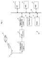
- Fig. 7 is a block diagram illustrating a structure of clock system 100 in accordance with the seventh embodiment.
- the same sections already shown in Fig. 6 bear the same reference marks used in Fig. 6.
- One-second pulse generating circuit 27 is coupled to CPU 15 through internal BUS 20.
- CPU 15 controls the generation of the one-second pulse by synchronising this pulse with a control signal from the CPU.
- a signal from a stationary satellite is received by antenna 11, then converted to an intermediate-frequency-signal at analogue-signal-processing-circuit 12.
- the signal runs to A/D converter 13 and digital-signal-processing-circuit 14, where the data is acquired.
- the acquired data is then supplied to CPU 15.
- CPU 15 calculates the time using the data, and outputs the data to an external device.
- CPU 15 When calculating the time, CPU 15 thus controls the one-second-pulse generation in one-second pulse generating circuit 27.
- Circuit 27 issues a one-second pulse just when a fractional value less than a second is reduced to zero (0).
- This one-second pulse is supplied together with the time figured out by CPU 15 to the external device through output-interface 26 for synchronising the time of the external device.
- CPU 15 always adds one second to the time data, thereby outputting the time data in phase with the fall of the one-second pulse, or CPU 15 outputs the time data in advance of normal time by approx. 0.5 seconds considering a delay due to transfer to the external device.
- the exact time can be acquired.
Landscapes
- Engineering & Computer Science (AREA)
- Radar, Positioning & Navigation (AREA)
- Remote Sensing (AREA)
- Physics & Mathematics (AREA)
- General Physics & Mathematics (AREA)
- Electric Clocks (AREA)
- Position Fixing By Use Of Radio Waves (AREA)
Applications Claiming Priority (2)
| Application Number | Priority Date | Filing Date | Title |
|---|---|---|---|
| JP16988499A JP2001004764A (ja) | 1999-06-16 | 1999-06-16 | 時計装置 |
| JP16988499 | 1999-06-16 |
Publications (2)
| Publication Number | Publication Date |
|---|---|
| EP1079285A2 true EP1079285A2 (de) | 2001-02-28 |
| EP1079285A3 EP1079285A3 (de) | 2005-04-06 |
Family
ID=15894752
Family Applications (1)
| Application Number | Title | Priority Date | Filing Date |
|---|---|---|---|
| EP20000112676 Withdrawn EP1079285A3 (de) | 1999-06-16 | 2000-06-15 | Uhrenverfahren |
Country Status (3)
| Country | Link |
|---|---|
| US (1) | US6563765B1 (de) |
| EP (1) | EP1079285A3 (de) |
| JP (1) | JP2001004764A (de) |
Cited By (4)
| Publication number | Priority date | Publication date | Assignee | Title |
|---|---|---|---|---|
| WO2007119599A1 (en) * | 2006-03-31 | 2007-10-25 | Casio Computer Co., Ltd. | Time correction control apparatus and method of time correction control |
| WO2012158348A1 (en) * | 2011-05-13 | 2012-11-22 | The Charles Stark Draper Laboratory, Inc. | Systems and methods for clock correction |
| US8385156B2 (en) | 2005-06-30 | 2013-02-26 | Seiko Precision Inc. | Radio-controlled adjustment timepiece |
| CN104076683A (zh) * | 2013-03-29 | 2014-10-01 | 精工爱普生株式会社 | 电子钟表及电子钟表的接收控制方法 |
Families Citing this family (35)
| Publication number | Priority date | Publication date | Assignee | Title |
|---|---|---|---|---|
| DE10040035B4 (de) * | 2000-08-11 | 2005-10-06 | T-Mobile Deutschland Gmbh | Verfahren zur Synchronisation der internen Uhr eines Mobilfunkendgeräts mit der lokalen Zeit |
| JP2002304313A (ja) * | 2001-04-05 | 2002-10-18 | Canon Inc | 情報蓄積システム及び情報管理システム |
| KR100760803B1 (ko) * | 2001-04-16 | 2007-09-20 | 주식회사 케이티 | 위성을 이용한 시각/주파수 동기시스템의 수신 장치 및 그방법 |
| JP2002353828A (ja) * | 2001-05-28 | 2002-12-06 | Funai Electric Co Ltd | デジタル放送受信機 |
| JP4433403B2 (ja) * | 2002-09-06 | 2010-03-17 | シチズンホールディングス株式会社 | 電波修正時計及びその制御方法 |
| KR20040092259A (ko) * | 2003-04-25 | 2004-11-03 | 삼성전자주식회사 | 기지국 장치를 위한 위성 클럭 동기 시스템 및 이를이용한 기지국 시스템의 위성 클럭 동기화 방법 |
| US6958953B2 (en) * | 2003-05-13 | 2005-10-25 | International Business Machines Corporation | Real time clock circuit having an internal clock generator |
| JP4295020B2 (ja) * | 2003-06-09 | 2009-07-15 | シチズンホールディングス株式会社 | 電波修正時計、電子機器、時刻修正方法および時刻修正プログラム |
| US20050073911A1 (en) * | 2003-10-06 | 2005-04-07 | Barnett Steven R. | Electronic prayer alert |
| JP2005269759A (ja) * | 2004-03-18 | 2005-09-29 | Meidensha Corp | サンプリング同期方式および時間管理方式 |
| US20050259722A1 (en) * | 2004-05-21 | 2005-11-24 | Reginald Vanlonden | Wireless clock system |
| KR100718544B1 (ko) * | 2004-08-06 | 2007-05-29 | 소상범 | 엘이디 무브먼트 시계 |
| US20060156342A1 (en) * | 2005-01-11 | 2006-07-13 | Pioneer Research Center Usa, Inc. | Generating consistent time for an electronic program guide |
| JP2008032636A (ja) * | 2006-07-31 | 2008-02-14 | Seiko Epson Corp | 時刻修正装置、時刻修正装置付き計時装置及び時刻修正方法 |
| JP2008170232A (ja) * | 2007-01-10 | 2008-07-24 | Seiko Epson Corp | 時刻修正装置、時刻修正装置付き計時装置及び時刻修正方法 |
| JP2008170229A (ja) * | 2007-01-10 | 2008-07-24 | Seiko Epson Corp | 時刻修正装置、時刻修正装置付き計時装置及び時刻修正方法 |
| JP2008170230A (ja) * | 2007-01-10 | 2008-07-24 | Seiko Epson Corp | 時刻修正装置、時刻修正装置付き計時装置及び時刻修正方法 |
| JP2008170228A (ja) * | 2007-01-10 | 2008-07-24 | Seiko Epson Corp | 時刻修正装置、時刻修正装置付き計時装置及び時刻修正方法 |
| JP2008170231A (ja) * | 2007-01-10 | 2008-07-24 | Seiko Epson Corp | 時刻修正装置、時刻修正装置付き計時装置及び時刻修正方法 |
| JP2008209248A (ja) * | 2007-02-27 | 2008-09-11 | Furuno Electric Co Ltd | タイミング信号発生装置 |
| JP2009133776A (ja) * | 2007-11-30 | 2009-06-18 | Sony Corp | 撮像装置と時刻修正方法 |
| US7956805B2 (en) * | 2008-04-11 | 2011-06-07 | Qualcomm Incorporated | System and/or method for obtaining a time reference for a received SPS signal |
| JP5251372B2 (ja) * | 2008-09-04 | 2013-07-31 | セイコーエプソン株式会社 | 電子時計 |
| JP4831154B2 (ja) * | 2008-09-30 | 2011-12-07 | ブラザー工業株式会社 | 計時装置 |
| JP5310426B2 (ja) * | 2009-09-15 | 2013-10-09 | セイコーエプソン株式会社 | 電子時計および電子時計の時刻修正方法 |
| JP5209769B2 (ja) * | 2011-09-16 | 2013-06-12 | セイコープレシジョン株式会社 | 電波修正時計 |
| CN102722099B (zh) * | 2012-06-13 | 2014-06-04 | 东莞市洲进钟表有限公司 | 具有计算误差功能的时钟校正系统的校时方法 |
| JP6398234B2 (ja) * | 2014-03-07 | 2018-10-03 | セイコーエプソン株式会社 | 衛星信号受信装置、電子時計、および衛星信号受信方法 |
| JP6187406B2 (ja) * | 2014-07-18 | 2017-08-30 | カシオ計算機株式会社 | 電子時計 |
| US10197680B2 (en) * | 2014-08-15 | 2019-02-05 | Samsung Electronics Co., Ltd | GNSS receiver |
| CN108141635A (zh) | 2015-10-15 | 2018-06-08 | 索尼公司 | 接收装置、发送装置和数据处理方法 |
| CN106454473B (zh) * | 2016-10-08 | 2019-12-03 | Oppo广东移动通信有限公司 | 时钟调节方法、装置、终端及播放系统 |
| CN109738954B (zh) * | 2019-03-14 | 2024-03-15 | 南方科技大学 | 一种时钟同步电路、时钟同步方法和海底地震仪 |
| CN110687829A (zh) * | 2019-10-28 | 2020-01-14 | 上海机电工程研究所 | 精度大于设定阈值的仿真时钟实现方法、系统、介质及设备 |
| WO2023002681A1 (ja) * | 2021-07-20 | 2023-01-26 | コニカミノルタ株式会社 | 情報処理システムおよび情報処理プログラム |
Family Cites Families (16)
| Publication number | Priority date | Publication date | Assignee | Title |
|---|---|---|---|---|
| US4014166A (en) * | 1976-02-13 | 1977-03-29 | The United States Of America As Represented By The Secretary Of Commerce | Satellite controlled digital clock system |
| US4204398A (en) * | 1977-09-16 | 1980-05-27 | Lemelson Jerome H | Method and means for automatically setting timepieces in a time zone |
| US4287597A (en) * | 1978-09-05 | 1981-09-01 | Arbiter Systems Incorporated | Satellite controlled clock |
| JPS58111784A (ja) * | 1981-12-25 | 1983-07-02 | Nec Corp | 時刻の遠隔較正方式 |
| US4494211A (en) * | 1982-11-24 | 1985-01-15 | The United States Of America As Represented By The Secretary Of The Navy | Balanced system for ranging and synchronization between satellite pairs |
| US4501502A (en) * | 1983-07-21 | 1985-02-26 | James Van Orsdel | Apparatus and method for timekeeping and time correction for analog timepiece |
| US4823328A (en) * | 1987-08-27 | 1989-04-18 | Conklin Charles C | Radio signal controlled digital clock |
| US5408444A (en) * | 1991-06-19 | 1995-04-18 | Casio Computer Co., Ltd. | Electronic timepiece capable of receiving signals from satellites |
| JPH07109434B2 (ja) * | 1991-11-19 | 1995-11-22 | 株式会社精工舎 | 時 計 |
| US5323322A (en) * | 1992-03-05 | 1994-06-21 | Trimble Navigation Limited | Networked differential GPS system |
| US5812205A (en) * | 1994-05-04 | 1998-09-22 | Starsight Telecast Incorporated | Automatic time set in a television system |
| FR2726412B1 (fr) * | 1994-10-28 | 1997-01-10 | Centre Nat Etd Spatiales | Procede de determination en temps reel de l'ecart de temps entre stations d'un systeme de radio-localisation-navigation |
| WO1996022546A1 (en) * | 1995-01-17 | 1996-07-25 | The Board Of Trustees Of The Leland Stanford Junior University | Wide area differential gps reference system and method |
| JP3789556B2 (ja) | 1996-06-25 | 2006-06-28 | 古野電気株式会社 | 電子時計およびクロックタイミング調整方法 |
| CA2187063A1 (en) * | 1996-10-03 | 1998-04-03 | Roger John La Salle | Synchronization of a timepiece to a reference time |
| AUPO986997A0 (en) * | 1997-10-20 | 1997-11-13 | H.P.M. Technologies Pty. Ltd. | Synchronizing a timepiece to a reference time |
-
1999
- 1999-06-16 JP JP16988499A patent/JP2001004764A/ja active Pending
-
2000
- 2000-06-15 EP EP20000112676 patent/EP1079285A3/de not_active Withdrawn
- 2000-06-15 US US09/595,044 patent/US6563765B1/en not_active Expired - Fee Related
Cited By (7)
| Publication number | Priority date | Publication date | Assignee | Title |
|---|---|---|---|---|
| US8385156B2 (en) | 2005-06-30 | 2013-02-26 | Seiko Precision Inc. | Radio-controlled adjustment timepiece |
| WO2007119599A1 (en) * | 2006-03-31 | 2007-10-25 | Casio Computer Co., Ltd. | Time correction control apparatus and method of time correction control |
| US7529157B2 (en) | 2006-03-31 | 2009-05-05 | Casio Computer Co., Ltd. | Time correction control apparatus and method of time correction control |
| WO2012158348A1 (en) * | 2011-05-13 | 2012-11-22 | The Charles Stark Draper Laboratory, Inc. | Systems and methods for clock correction |
| US8466835B2 (en) | 2011-05-13 | 2013-06-18 | The Charles Stark Draper Laboratory, Inc. | Systems and methods for clock correction |
| CN104076683A (zh) * | 2013-03-29 | 2014-10-01 | 精工爱普生株式会社 | 电子钟表及电子钟表的接收控制方法 |
| CN104076683B (zh) * | 2013-03-29 | 2017-08-25 | 精工爱普生株式会社 | 电子钟表及电子钟表的接收控制方法 |
Also Published As
| Publication number | Publication date |
|---|---|
| US6563765B1 (en) | 2003-05-13 |
| JP2001004764A (ja) | 2001-01-12 |
| EP1079285A3 (de) | 2005-04-06 |
Similar Documents
| Publication | Publication Date | Title |
|---|---|---|
| US6563765B1 (en) | Clock system | |
| US20100034190A1 (en) | Apparatus for wireless communication and method for synchronizing time thereof | |
| US7084810B2 (en) | Portable terminal and GPS time keeping method | |
| JP3789556B2 (ja) | 電子時計およびクロックタイミング調整方法 | |
| EP2853959B1 (de) | Elektronische uhr und steuerungsverfahren dafür | |
| US8514667B2 (en) | Electronic timepiece and reception control method for an electronic timepiece | |
| EP2256941A2 (de) | Kombinierter Satellitennavigationsempfänger / Kommunikationsgerät | |
| US7813225B2 (en) | Time adjustment device, timepiece with a time adjustment device, and time adjustment method | |
| JP5333014B2 (ja) | 電子機器および電子機器の閏秒更新情報受信方法 | |
| US9869977B2 (en) | Radio-controlled timepiece | |
| EP2515187A1 (de) | Elektronische Uhr und Zeitanpassungsverfahren | |
| JP2011163803A (ja) | 無線中継装置及び報知方法 | |
| US20080165627A1 (en) | Time Adjustment Device, Timepiece with a Time Adjustment Device, and Time Adjustment Method | |
| US20080165624A1 (en) | Time Adjustment Device, Timepiece with a Time Adjustment Device, and Time Adjustment Method | |
| JP2001051077A (ja) | 時刻修正用情報出力装置および自動時刻修正時計 | |
| JP6819308B2 (ja) | 電子時計 | |
| EP0933689B1 (de) | Verwaltungssytem für zeitinformationen | |
| US20090016167A1 (en) | Time Adjustment Device, Timekeeping Device with a Time Adjustment Device, and a Time Adjustment Method | |
| JP2011226813A (ja) | Gps計時装置およびその方法 | |
| JP2010216999A (ja) | 電子機器およびその制御方法 | |
| JP2005083990A (ja) | 時刻情報検出方法、時刻情報検出装置および電波修正時計 | |
| JPH11118962A (ja) | 標準時計装置 | |
| JP2015206695A (ja) | 電波時計 | |
| JPH08297178A (ja) | 電子時計 | |
| KR20090124746A (ko) | 방송의 시보 서비스를 이용한 상용 알티시의 위상동기 방법및 장치 |
Legal Events
| Date | Code | Title | Description |
|---|---|---|---|
| PUAI | Public reference made under article 153(3) epc to a published international application that has entered the european phase |
Free format text: ORIGINAL CODE: 0009012 |
|
| AK | Designated contracting states |
Kind code of ref document: A2 Designated state(s): AT BE CH CY DE DK ES FI FR GB GR IE IT LI LU MC NL PT SE |
|
| AX | Request for extension of the european patent |
Free format text: AL;LT;LV;MK;RO;SI |
|
| PUAL | Search report despatched |
Free format text: ORIGINAL CODE: 0009013 |
|
| AK | Designated contracting states |
Kind code of ref document: A3 Designated state(s): AT BE CH CY DE DK ES FI FR GB GR IE IT LI LU MC NL PT SE |
|
| AX | Request for extension of the european patent |
Extension state: AL LT LV MK RO SI |
|
| 17P | Request for examination filed |
Effective date: 20050525 |
|
| AKX | Designation fees paid |
Designated state(s): DE FR GB |
|
| 17Q | First examination report despatched |
Effective date: 20080225 |
|
| RAP1 | Party data changed (applicant data changed or rights of an application transferred) |
Owner name: PANASONIC CORPORATION |
|
| STAA | Information on the status of an ep patent application or granted ep patent |
Free format text: STATUS: THE APPLICATION IS DEEMED TO BE WITHDRAWN |
|
| 18D | Application deemed to be withdrawn |
Effective date: 20080708 |