EP1079349A2 - Détection de la position et du mouvement d'images au niveau des sous-pixels - Google Patents
Détection de la position et du mouvement d'images au niveau des sous-pixels Download PDFInfo
- Publication number
- EP1079349A2 EP1079349A2 EP00307249A EP00307249A EP1079349A2 EP 1079349 A2 EP1079349 A2 EP 1079349A2 EP 00307249 A EP00307249 A EP 00307249A EP 00307249 A EP00307249 A EP 00307249A EP 1079349 A2 EP1079349 A2 EP 1079349A2
- Authority
- EP
- European Patent Office
- Prior art keywords
- detector
- detectors
- image
- array
- view
- Prior art date
- Legal status (The legal status is an assumption and is not a legal conclusion. Google has not performed a legal analysis and makes no representation as to the accuracy of the status listed.)
- Granted
Links
Images


Classifications
-
- G—PHYSICS
- G08—SIGNALLING
- G08B—SIGNALLING SYSTEMS, e.g. PERSONAL CALLING SYSTEMS; ORDER TELEGRAPHS; ALARM SYSTEMS
- G08B13/00—Burglar, theft or intruder alarms
- G08B13/18—Actuation by interference with heat, light, or radiation of shorter wavelength; Actuation by intruding sources of heat, light, or radiation of shorter wavelength
- G08B13/189—Actuation by interference with heat, light, or radiation of shorter wavelength; Actuation by intruding sources of heat, light, or radiation of shorter wavelength using passive radiation detection systems
- G08B13/19—Actuation by interference with heat, light, or radiation of shorter wavelength; Actuation by intruding sources of heat, light, or radiation of shorter wavelength using passive radiation detection systems using infrared-radiation detection systems
- G08B13/191—Actuation by interference with heat, light, or radiation of shorter wavelength; Actuation by intruding sources of heat, light, or radiation of shorter wavelength using passive radiation detection systems using infrared-radiation detection systems using pyroelectric sensor means
Definitions
- the present invention relates to a method of determining the position and/or motion of an object using an array of radiation detectors.
- the invention will be described below with reference to arrays of pyroelectric detectors but may be equally applicable to some other arrays of radiation detectors.
- a pyroelectric sensor is composed of a thin piece of pyroelectric material with electrodes on the top and bottom surfaces
- the pyroelectric material has the property that changes in incident (heat) energy are translated to electrical signals that can be taken from the electrodes via a suitable amplifier for signal processing.
- PIR detector Passive Infrared
- intruder detectors and movement triggered automatic lights.
- Conventional PIR detectors use a small number of pyroelectric sensors in conjunction with an optical arrangement that defines the field of view and provides a modulated signal from a moving human, as described in more detail below.
- This arrangement is that it is not possible to determine the location of the object within the field of view of the detector, and another is that gaps must be provided within the overall field of view for the detection method to operate, resulting in blind spots.
- a solution to these shortcomings can be found by replacing the conventional pyroelectric sensor with an array of pyroelectric detectors and a unitary optical system. By tracking the movement of an object between adjacent detectors of the array, the angular position of the object with respect to the detector is known. This detection method is also outlined below. The use of an array also provides continuous coverage throughout the field of view.
- the present invention provides a means for enhancing the performance of an array-based detector, primarily by allowing the detection of movement of an object within the field of view of a single detector in an array of detectors
- the detector With conventional PIR detectors, it is normal for the detector to comprise a pyroelectric sensor with 1, 2 or 4 sensitive detectors, an optical device defining the field of view of these detectors, an amplifier and signal processing circuitry
- the optical device is usually an array of lens segments arranged to direct the field of view of the sensor into a number of finger-like detection zones as shown in Figure 1(a).
- each lens segment projects one detection zone, but when there are two or more pyroelectric detectors, each lens segment will project a detection zone for each detector in the sensor.
- Figure 1(a) shows the most common arrangement, where there are two detectors in the sensor 1 and each lens segment A, B, C, D, E projects a pair of detection zones. The gaps in the coverage pattern can be seen between these detection zones.
- the pyroelectric detectors are arranged so that one provides a positive signal when the heat from the object is focused upon it, while the other provides a negative signal when the heat is focused upon it.
- each lens segment will project a pair of detection zones, one with a positive sense and the other with a negative sense.
- the nature of the pyroelectric sensors is such that they detect changes in incident radiation but ignore steady state radiation.
- the array of lenses is often replaced with an array of mirrors, but as these are optically equivalent, the detection method is essentially the same.
- the overall field of view can be determined in the same way as for a conventional camera, by placing the array on the focal plane of an appropriate lens.
- a sensor using an array of 25 detectors arranged in a 5x5 square.
- the field of view is focused onto this array through a spherical lens, it is broken up into 25 "pixels" in a square pattern, matching the array (see Figure 2(b)). It is as if the overall field of view had been overlaid by a square grid, with each detector of the array viewing one square of the grid A1, A2 ... B1, B2 etc.
- the field of view of each detector of an array is contiguous with its neighbours, providing continuous coverage throughout the field of view.
- the obvious method for detecting movement and position using an array is to detect the movement of an object (or the edge of an object) from the field of view of one detector to another. This restricts the resolution of the detection process to the size of the field of view subtended by each detector of the array. In the case of a 15x15 array placed at the focus of a spherical lens with a 90° field of view, the field of view of each detector will subtend an arc approximately I m wide, at a distance of 10m from the detector. As any movement of an object within this pixel is not detected, this sets a limit to the effective range that can be claimed when there is a requirement to detect a specified amount of movement by an object. If the detector were required to give an alarm with less than 0.5m of movement by a person, the detector described above would have its effective range limited to less than 5m. This issue is of importance in meeting regulatory requirements in certain applications areas.
- the present invention can be used to determine the position and/or movement of an object within the field of view of a single detector in an array of detectors, thereby increasing the apparent resolution of the array. It also provides a mechanism for differentiating between static objects with modulated output energy, and objects oscillating about a mean position.
- the proposed method applies to arrays constructed from single pieces of appropriate material and makes use of energy focused onto one detector of the array, being diffused onto adjacent detectors through the body of the material used to construct the array
- This diffusion of energy has previously been considered a negative attribute of such detectors, as it reduces image sharpness.
- This invention turns this negative attribute into a benefit, expanding the capabilities of such detector arrays.
- the present invention provides a method for determining the location and/or movement of an image within the field of view of one detector in an array of pyroelectric detectors constructed from a single piece of material and having an optical system for producing an image of an object on the array, comprising:
- the comparison comprises determining the ratio of the signal(s) from two detectors located opposite to each other on either side of the first detector. When the image is halfway between these detectors the ratio is equal, and when the image is closer to one detector the ratio moves to favour that detector and reduces in a corresponding manner for the other detector.
- the method may also be used to determine the net movement of an object within the field of view of a first detector by comparing the signals of a pair of detectors, diametrically opposed across the first detector, by averaging the ratios of the signals over a period of time.
- An object which oscillates about a mean position in the field of view of the first detector will give rise to an equal ratio of the signals from the adjacent pair of detectors when their signals are averaged over a period significantly longer than the period of oscillation of the object.
- the invention also provides a detector having means for carrying out the above methods.
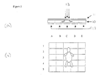
- Figure 2 shows a simplified pyroelectric detector array constructed from a single piece of pyroelectric material 10, with electrodes formed by the deposition of appropriate electrode materials.
- a common electrode 11 is formed on the top surface and the individual detectors of the array formed by the segmented electrode 12 on the lower surface.
- the array will typically view a scene and energy from the scene will be focussed onto the array by suitable optics. Energy 13 focused on one detector will diffuse laterally through the material and generate signals in adjacent detectors.
- the incident energy is focused on one detector (e.g.C3)
- the energy will diffuse into the adjacent detectors (B2, B3, B4, C2, C4, D2, D3 and D4). If the energy is focused in the centre of C3, each detector in the opposing pairs of adjacent detectors (C2/C4, B2/D4, B3/D3, and B4/D2) will have equal signals.
- the magnitude of the signals in the diagonal pairs (B2/D4 and B4/D2) will be different to those in the vertical and horizontal pairs (C2/C4 and B3/D3) because of the different path lengths from C3, but the ratios of their signal will be the same.
- the focus of the energy incident on detector C3 is offset to one edge of that detector, e.g.
- the method of the invention also provides a means for discriminating between static objects, whose energy output may fluctuate and so make it visible to a pyroelectric detector, and moving objects.
- a moving object that enters or leaves the field of view of one detector in an array generates a change in the energy incident on that detector
- a static object that has a fluctuating energy output also generates a change in the energy incident on the detector.
- the discrimination between objects moving through the field of view of a detector and other objects can be further enhanced by identifying objects that have an oscillatory movement and exhibit no net movement across the field of view, e.g. a swinging light bulb.
- Discrimination is achieved by first identifying the detector receiving the incident radiation and selecting an opposing pair of detectors about the first detector whose axis is essentially parallel to the movement of the object.
- the ratios of the signals from the opposing pairs of elements are averaged over a period of time significantly longer than the period of oscillation of the object.
- a swinging object will exhibit a very small average movement over a given period of time, compared with a object moving through the field of view, as the movement achieved by the swing in one direction will mostly be cancelled by the movement on the return swing.
- a further capability offered by this technique is the early detection of the onset of movement by a previously stationary object.
- the pyroelectric detectors of the array are not responsive to stationary objects, but as soon as the object starts to move signals will appear, by the same mechanism as described above, on the adjacent pairs of detectors. By this means the onset of movement of an object can be sensed before it leaves the field of view of the first detector
- the magnitude of the signals generated in pyroelectric detectors is proportional to the difference in temperature between the object and its background.
- the method uses the ratios of signals from pairs of detectors in opposition about the detector receiving the incident radiation in its detection process, rather than absolute values, this process is less sensitive to the effects of change in background temperature than is normal with conventional detection methods. It is possible to gain some information about the location of the object by determining the ratio of the signal from the detector receiving the incident radiation with that from an adjacent detector (the higher the ratio, the closer is the object to the adjacent detector) but this calculation is open to errors arising from the size and location of the image in the first detector.
Landscapes
- General Physics & Mathematics (AREA)
- Physics & Mathematics (AREA)
- Photometry And Measurement Of Optical Pulse Characteristics (AREA)
- Closed-Circuit Television Systems (AREA)
- Geophysics And Detection Of Objects (AREA)
- Radiation Pyrometers (AREA)
- Analysing Materials By The Use Of Radiation (AREA)
- Length Measuring Devices By Optical Means (AREA)
- Burglar Alarm Systems (AREA)
- Image Analysis (AREA)
- Details Of Television Scanning (AREA)
- Color Television Image Signal Generators (AREA)
- Endoscopes (AREA)
Applications Claiming Priority (2)
| Application Number | Priority Date | Filing Date | Title |
|---|---|---|---|
| GB9920443A GB2353856B (en) | 1999-08-27 | 1999-08-27 | Improvements in position determination using arrays of radiation detectors |
| GB9920443 | 1999-08-27 |
Publications (3)
| Publication Number | Publication Date |
|---|---|
| EP1079349A2 true EP1079349A2 (fr) | 2001-02-28 |
| EP1079349A3 EP1079349A3 (fr) | 2002-02-06 |
| EP1079349B1 EP1079349B1 (fr) | 2004-04-21 |
Family
ID=10860001
Family Applications (1)
| Application Number | Title | Priority Date | Filing Date |
|---|---|---|---|
| EP00307249A Expired - Lifetime EP1079349B1 (fr) | 1999-08-27 | 2000-08-23 | Détection de la position et du mouvement d'images au niveau des sous-pixels |
Country Status (6)
| Country | Link |
|---|---|
| US (1) | US6528788B1 (fr) |
| EP (1) | EP1079349B1 (fr) |
| JP (1) | JP4376436B2 (fr) |
| AT (1) | ATE265077T1 (fr) |
| DE (1) | DE60009996T2 (fr) |
| GB (1) | GB2353856B (fr) |
Cited By (2)
| Publication number | Priority date | Publication date | Assignee | Title |
|---|---|---|---|---|
| WO2014043160A1 (fr) * | 2012-09-14 | 2014-03-20 | Motorola Solutions, Inc. | Ajustement de fonctionnalités panoramique/inclinaison/zoom (ptz) de caméra de surveillance sur la base de données d'incident historiques |
| WO2014070571A1 (fr) * | 2012-10-31 | 2014-05-08 | Motorola Solutions, Inc. | Procédé et appareil de sélection d'un algorithme d'analyse vidéo sur la base de données d'incidents historiques |
Families Citing this family (9)
| Publication number | Priority date | Publication date | Assignee | Title |
|---|---|---|---|---|
| GB2365120B (en) | 2000-07-21 | 2004-11-17 | Infrared Integrated Syst Ltd | Multipurpose detector |
| GB2373389B (en) * | 2001-03-12 | 2003-03-12 | Infrared Integrated Syst Ltd | A method of multiplexing column amplifiers in a resistive bolometer array |
| GB2384935A (en) * | 2002-02-02 | 2003-08-06 | Qinetiq Ltd | Edge detecting focal plane detector |
| DE202009018974U1 (de) * | 2009-03-02 | 2015-01-22 | Infratec Gmbh | Sensor zur winkelaufgelösten Erfassung von Flammen oder Bränden |
| DE102012107739B4 (de) * | 2012-08-22 | 2023-11-02 | Avago Technologies International Sales Pte. Ltd. | Sensorsystem zum Erkennen einer Bewegung einer Infrarotlichtquelle |
| EP3405927B1 (fr) | 2016-01-20 | 2024-10-16 | Carrier Corporation | Système de gestion de bâtiment utilisant une détection et un suivi d'objet dans un grand espace avec un capteur à basse résolution |
| US10186124B1 (en) | 2017-10-26 | 2019-01-22 | Scott Charles Mullins | Behavioral intrusion detection system |
| AU2020272775A1 (en) | 2019-04-10 | 2021-11-18 | Raptor Vision, Llc | Monitoring systems |
| RU2768570C1 (ru) * | 2021-04-29 | 2022-03-24 | Закрытое акционерное общество "Производственное объединение "Спецавтоматика" | Способ автоматического координатного обнаружения очагов возгораний |
Family Cites Families (9)
| Publication number | Priority date | Publication date | Assignee | Title |
|---|---|---|---|---|
| US3581092A (en) * | 1969-04-09 | 1971-05-25 | Barnes Eng Co | Pyroelectric detector array |
| JPS56143965A (en) * | 1980-04-10 | 1981-11-10 | Mitsubishi Electric Corp | Bearing searching apparatus |
| GB2208256B (en) * | 1983-04-15 | 1989-07-26 | Philips Electronic Associated | Infra-red radiation imaging devices and systems |
| JPH0749925B2 (ja) * | 1989-03-01 | 1995-05-31 | 浜松ホトニクス株式会社 | 2次元入射位置検出装置 |
| US5101194A (en) | 1990-08-08 | 1992-03-31 | Sheffer Eliezer A | Pattern-recognizing passive infrared radiation detection system |
| FR2672988A1 (fr) * | 1991-02-15 | 1992-08-21 | Sodern | Procede de mesure de la position precise du centre energetique d'une tache image d'un objet lumineux sur un detecteur photosensible. |
| US5311305A (en) * | 1992-06-30 | 1994-05-10 | At&T Bell Laboratories | Technique for edge/corner detection/tracking in image frames |
| US5332176A (en) * | 1992-12-03 | 1994-07-26 | Electronics & Space Corp. | Controlled interlace for TOW missiles using medium wave infrared sensor or TV sensor |
| JPH07159236A (ja) * | 1993-12-03 | 1995-06-23 | Murata Mfg Co Ltd | 熱源検知装置 |
-
1999
- 1999-08-27 GB GB9920443A patent/GB2353856B/en not_active Revoked
-
2000
- 2000-08-21 US US09/643,099 patent/US6528788B1/en not_active Expired - Lifetime
- 2000-08-23 EP EP00307249A patent/EP1079349B1/fr not_active Expired - Lifetime
- 2000-08-23 AT AT00307249T patent/ATE265077T1/de not_active IP Right Cessation
- 2000-08-23 DE DE60009996T patent/DE60009996T2/de not_active Expired - Lifetime
- 2000-08-28 JP JP2000257862A patent/JP4376436B2/ja not_active Expired - Lifetime
Cited By (5)
| Publication number | Priority date | Publication date | Assignee | Title |
|---|---|---|---|---|
| WO2014043160A1 (fr) * | 2012-09-14 | 2014-03-20 | Motorola Solutions, Inc. | Ajustement de fonctionnalités panoramique/inclinaison/zoom (ptz) de caméra de surveillance sur la base de données d'incident historiques |
| GB2519492A (en) * | 2012-09-14 | 2015-04-22 | Motorola Solutions Inc | Adjusting surveillance camera PTZ tours based on historical incident data |
| GB2519492B (en) * | 2012-09-14 | 2017-05-24 | Motorola Solutions Inc | Adjusting surveillance camera PTZ tours based on historical incident data |
| WO2014070571A1 (fr) * | 2012-10-31 | 2014-05-08 | Motorola Solutions, Inc. | Procédé et appareil de sélection d'un algorithme d'analyse vidéo sur la base de données d'incidents historiques |
| GB2520894A (en) * | 2012-10-31 | 2015-06-03 | Motorola Solutions Inc | Method and apparatus for video analysis algorithm selection based on historical incident data |
Also Published As
| Publication number | Publication date |
|---|---|
| EP1079349A3 (fr) | 2002-02-06 |
| GB2353856A (en) | 2001-03-07 |
| EP1079349B1 (fr) | 2004-04-21 |
| ATE265077T1 (de) | 2004-05-15 |
| US6528788B1 (en) | 2003-03-04 |
| JP2001133561A (ja) | 2001-05-18 |
| GB9920443D0 (en) | 1999-11-03 |
| DE60009996D1 (de) | 2004-05-27 |
| JP4376436B2 (ja) | 2009-12-02 |
| GB2353856B (en) | 2001-10-24 |
| DE60009996T2 (de) | 2004-09-02 |
Similar Documents
| Publication | Publication Date | Title |
|---|---|---|
| JP5799211B2 (ja) | 距離画像センサ | |
| US8314390B2 (en) | PIR motion sensor system | |
| EP1079349B1 (fr) | Détection de la position et du mouvement d'images au niveau des sous-pixels | |
| US6211522B1 (en) | Passive infra-red intrusion sensor | |
| US20180197909A1 (en) | Optical sensing with tessellated diffraction-pattern generators | |
| US6600878B2 (en) | Autofocus sensor | |
| US5818337A (en) | Masked passive infrared intrusion detection device and method of operation therefore | |
| US5565683A (en) | Heat source detector | |
| US4749862A (en) | Scanning fire-monitoring system | |
| JPH0694535A (ja) | 熱画像検出装置 | |
| US10284825B2 (en) | Systems with integrated refractive and diffractive optics | |
| CA2300644C (fr) | Detecteur de mouvement passif a infrarouge a l'epreuve des animaux de compagnie | |
| TW200901011A (en) | Speckle navigation system that emphasize the speckle signal | |
| US3792275A (en) | Infrared intrusion sensor | |
| JPH09304188A (ja) | 赤外線検出装置 | |
| KR960015008B1 (ko) | 열화상검출수단을 가진 방재검지장치 | |
| KR20210094872A (ko) | 다중센서를 활용한 통합 감시 시스템 | |
| US8184003B1 (en) | Motion detection and locating apparatus and method | |
| US4691107A (en) | Infra red photo detector systems | |
| Jones et al. | A novel approach for surveillance using visual and thermal images | |
| Porter et al. | Low cost smart sensors using infrared detector arrays | |
| Blank et al. | New Sensing Systems for Securing Virtual Walls at Outdoor Based on True Differential Digital TMOS | |
| JPH08122144A (ja) | 赤外線検出器 | |
| JPH09113633A (ja) | 人体検知装置 | |
| KR200156672Y1 (ko) | 이동물체위치검출장치 |
Legal Events
| Date | Code | Title | Description |
|---|---|---|---|
| PUAI | Public reference made under article 153(3) epc to a published international application that has entered the european phase |
Free format text: ORIGINAL CODE: 0009012 |
|
| AK | Designated contracting states |
Kind code of ref document: A2 Designated state(s): AT BE CH CY DE DK ES FI FR GB GR IE IT LI LU MC NL PT SE |
|
| AX | Request for extension of the european patent |
Free format text: AL;LT;LV;MK;RO;SI |
|
| PUAL | Search report despatched |
Free format text: ORIGINAL CODE: 0009013 |
|
| AK | Designated contracting states |
Kind code of ref document: A3 Designated state(s): AT BE CH CY DE DK ES FI FR GB GR IE IT LI LU MC NL PT SE |
|
| AX | Request for extension of the european patent |
Free format text: AL;LT;LV;MK;RO;SI |
|
| RIC1 | Information provided on ipc code assigned before grant |
Free format text: 7G 08B 13/191 A, 7G 08B 13/194 B |
|
| 17P | Request for examination filed |
Effective date: 20020510 |
|
| AKX | Designation fees paid |
Free format text: AT BE CH CY DE DK ES FI FR GB GR IE IT LI LU MC NL PT SE |
|
| 17Q | First examination report despatched |
Effective date: 20021115 |
|
| GRAP | Despatch of communication of intention to grant a patent |
Free format text: ORIGINAL CODE: EPIDOSNIGR1 |
|
| GRAS | Grant fee paid |
Free format text: ORIGINAL CODE: EPIDOSNIGR3 |
|
| GRAA | (expected) grant |
Free format text: ORIGINAL CODE: 0009210 |
|
| AK | Designated contracting states |
Kind code of ref document: B1 Designated state(s): AT BE CH CY DE DK ES FI FR GB GR IE IT LI LU MC NL PT SE |
|
| PG25 | Lapsed in a contracting state [announced via postgrant information from national office to epo] |
Ref country code: NL Free format text: LAPSE BECAUSE OF FAILURE TO SUBMIT A TRANSLATION OF THE DESCRIPTION OR TO PAY THE FEE WITHIN THE PRESCRIBED TIME-LIMIT Effective date: 20040421 Ref country code: LI Free format text: LAPSE BECAUSE OF FAILURE TO SUBMIT A TRANSLATION OF THE DESCRIPTION OR TO PAY THE FEE WITHIN THE PRESCRIBED TIME-LIMIT Effective date: 20040421 Ref country code: FI Free format text: LAPSE BECAUSE OF FAILURE TO SUBMIT A TRANSLATION OF THE DESCRIPTION OR TO PAY THE FEE WITHIN THE PRESCRIBED TIME-LIMIT Effective date: 20040421 Ref country code: BE Free format text: LAPSE BECAUSE OF FAILURE TO SUBMIT A TRANSLATION OF THE DESCRIPTION OR TO PAY THE FEE WITHIN THE PRESCRIBED TIME-LIMIT Effective date: 20040421 Ref country code: CY Free format text: LAPSE BECAUSE OF FAILURE TO SUBMIT A TRANSLATION OF THE DESCRIPTION OR TO PAY THE FEE WITHIN THE PRESCRIBED TIME-LIMIT Effective date: 20040421 Ref country code: AT Free format text: LAPSE BECAUSE OF FAILURE TO SUBMIT A TRANSLATION OF THE DESCRIPTION OR TO PAY THE FEE WITHIN THE PRESCRIBED TIME-LIMIT Effective date: 20040421 Ref country code: CH Free format text: LAPSE BECAUSE OF FAILURE TO SUBMIT A TRANSLATION OF THE DESCRIPTION OR TO PAY THE FEE WITHIN THE PRESCRIBED TIME-LIMIT Effective date: 20040421 |
|
| REG | Reference to a national code |
Ref country code: GB Ref legal event code: FG4D |
|
| REG | Reference to a national code |
Ref country code: CH Ref legal event code: EP |
|
| REG | Reference to a national code |
Ref country code: IE Ref legal event code: FG4D |
|
| REF | Corresponds to: |
Ref document number: 60009996 Country of ref document: DE Date of ref document: 20040527 Kind code of ref document: P |
|
| PG25 | Lapsed in a contracting state [announced via postgrant information from national office to epo] |
Ref country code: DK Free format text: LAPSE BECAUSE OF FAILURE TO SUBMIT A TRANSLATION OF THE DESCRIPTION OR TO PAY THE FEE WITHIN THE PRESCRIBED TIME-LIMIT Effective date: 20040721 Ref country code: GR Free format text: LAPSE BECAUSE OF FAILURE TO SUBMIT A TRANSLATION OF THE DESCRIPTION OR TO PAY THE FEE WITHIN THE PRESCRIBED TIME-LIMIT Effective date: 20040721 Ref country code: SE Free format text: LAPSE BECAUSE OF FAILURE TO SUBMIT A TRANSLATION OF THE DESCRIPTION OR TO PAY THE FEE WITHIN THE PRESCRIBED TIME-LIMIT Effective date: 20040721 |
|
| PG25 | Lapsed in a contracting state [announced via postgrant information from national office to epo] |
Ref country code: ES Free format text: LAPSE BECAUSE OF FAILURE TO SUBMIT A TRANSLATION OF THE DESCRIPTION OR TO PAY THE FEE WITHIN THE PRESCRIBED TIME-LIMIT Effective date: 20040801 |
|
| PG25 | Lapsed in a contracting state [announced via postgrant information from national office to epo] |
Ref country code: IE Free format text: LAPSE BECAUSE OF NON-PAYMENT OF DUE FEES Effective date: 20040823 Ref country code: LU Free format text: LAPSE BECAUSE OF NON-PAYMENT OF DUE FEES Effective date: 20040823 |
|
| PG25 | Lapsed in a contracting state [announced via postgrant information from national office to epo] |
Ref country code: MC Free format text: LAPSE BECAUSE OF NON-PAYMENT OF DUE FEES Effective date: 20040831 |
|
| NLV1 | Nl: lapsed or annulled due to failure to fulfill the requirements of art. 29p and 29m of the patents act | ||
| REG | Reference to a national code |
Ref country code: CH Ref legal event code: PL |
|
| ET | Fr: translation filed | ||
| PLBE | No opposition filed within time limit |
Free format text: ORIGINAL CODE: 0009261 |
|
| STAA | Information on the status of an ep patent application or granted ep patent |
Free format text: STATUS: NO OPPOSITION FILED WITHIN TIME LIMIT |
|
| 26N | No opposition filed |
Effective date: 20050124 |
|
| REG | Reference to a national code |
Ref country code: IE Ref legal event code: MM4A |
|
| PG25 | Lapsed in a contracting state [announced via postgrant information from national office to epo] |
Ref country code: PT Free format text: LAPSE BECAUSE OF NON-PAYMENT OF DUE FEES Effective date: 20040921 |
|
| REG | Reference to a national code |
Ref country code: FR Ref legal event code: PLFP Year of fee payment: 17 |
|
| REG | Reference to a national code |
Ref country code: FR Ref legal event code: PLFP Year of fee payment: 18 |
|
| REG | Reference to a national code |
Ref country code: FR Ref legal event code: PLFP Year of fee payment: 19 |
|
| PGFP | Annual fee paid to national office [announced via postgrant information from national office to epo] |
Ref country code: FR Payment date: 20190826 Year of fee payment: 20 Ref country code: DE Payment date: 20190828 Year of fee payment: 20 Ref country code: IT Payment date: 20190826 Year of fee payment: 20 |
|
| PGFP | Annual fee paid to national office [announced via postgrant information from national office to epo] |
Ref country code: GB Payment date: 20190827 Year of fee payment: 20 |
|
| REG | Reference to a national code |
Ref country code: DE Ref legal event code: R071 Ref document number: 60009996 Country of ref document: DE |
|
| REG | Reference to a national code |
Ref country code: GB Ref legal event code: PE20 Expiry date: 20200822 |
|
| PG25 | Lapsed in a contracting state [announced via postgrant information from national office to epo] |
Ref country code: GB Free format text: LAPSE BECAUSE OF EXPIRATION OF PROTECTION Effective date: 20200822 |