EP1079477B1 - Elektrische Schnittstelleneinrichtung, insbesondere für mobile Büromöbel - Google Patents
Elektrische Schnittstelleneinrichtung, insbesondere für mobile Büromöbel Download PDFInfo
- Publication number
- EP1079477B1 EP1079477B1 EP00117168A EP00117168A EP1079477B1 EP 1079477 B1 EP1079477 B1 EP 1079477B1 EP 00117168 A EP00117168 A EP 00117168A EP 00117168 A EP00117168 A EP 00117168A EP 1079477 B1 EP1079477 B1 EP 1079477B1
- Authority
- EP
- European Patent Office
- Prior art keywords
- plug
- interface device
- electric
- pivot
- electric interface
- Prior art date
- Legal status (The legal status is an assumption and is not a legal conclusion. Google has not performed a legal analysis and makes no representation as to the accuracy of the status listed.)
- Expired - Lifetime
Links
- 239000004020 conductor Substances 0.000 claims description 7
- 230000001681 protective effect Effects 0.000 claims description 4
- 238000005538 encapsulation Methods 0.000 claims 1
- 239000011295 pitch Substances 0.000 description 2
- 230000004323 axial length Effects 0.000 description 1
- 230000006735 deficit Effects 0.000 description 1
- 230000005611 electricity Effects 0.000 description 1
- 230000037431 insertion Effects 0.000 description 1
- 238000003780 insertion Methods 0.000 description 1
- 238000005192 partition Methods 0.000 description 1
- 230000000149 penetrating effect Effects 0.000 description 1
- 238000007665 sagging Methods 0.000 description 1
Images


Classifications
-
- H—ELECTRICITY
- H01—ELECTRIC ELEMENTS
- H01R—ELECTRICALLY-CONDUCTIVE CONNECTIONS; STRUCTURAL ASSOCIATIONS OF A PLURALITY OF MUTUALLY-INSULATED ELECTRICAL CONNECTING ELEMENTS; COUPLING DEVICES; CURRENT COLLECTORS
- H01R13/00—Details of coupling devices of the kinds covered by groups H01R12/70 or H01R24/00 - H01R33/00
- H01R13/73—Means for mounting coupling parts to apparatus or structures, e.g. to a wall
- H01R13/74—Means for mounting coupling parts in openings of a panel
- H01R13/748—Means for mounting coupling parts in openings of a panel using one or more screws
-
- H—ELECTRICITY
- H01—ELECTRIC ELEMENTS
- H01R—ELECTRICALLY-CONDUCTIVE CONNECTIONS; STRUCTURAL ASSOCIATIONS OF A PLURALITY OF MUTUALLY-INSULATED ELECTRICAL CONNECTING ELEMENTS; COUPLING DEVICES; CURRENT COLLECTORS
- H01R13/00—Details of coupling devices of the kinds covered by groups H01R12/70 or H01R24/00 - H01R33/00
- H01R13/56—Means for preventing chafing or fracture of flexible leads at outlet from coupling part
- H01R13/562—Bending-relieving
-
- H—ELECTRICITY
- H01—ELECTRIC ELEMENTS
- H01R—ELECTRICALLY-CONDUCTIVE CONNECTIONS; STRUCTURAL ASSOCIATIONS OF A PLURALITY OF MUTUALLY-INSULATED ELECTRICAL CONNECTING ELEMENTS; COUPLING DEVICES; CURRENT COLLECTORS
- H01R35/00—Flexible or turnable line connectors, i.e. the rotation angle being limited
- H01R35/04—Turnable line connectors with limited rotation angle with frictional contact members
Definitions
- the invention relates to an electrical interface device especially for mobile office furniture according to the generic term of claim 1.
- Part-time work is becoming increasingly important. To the extent in which finds part-time work in authorities and companies, are also corresponding jobs from two and shared more workers.
- mobile office furniture is particularly enjoyable mobile office furniture containers, increasingly popular, in which the personal documents are kept and for Third parties cannot be locked off.
- the "mobile container garage” can be used for the individual mobile office containers be turned off.
- a Person drive their own container to their workplace.
- the container will be back completed and to its general repository pushed back. Now there is room and space for another person to work in that workplace would like to bring their own container there.
- a generic connector is for example known from DE-A-26 23 145.
- the plug part instructs a ball joint-like connection to one on a wall-mounted connection housing, so that over this the connector part in the manner of a ball joint connection in a sufficiently large cone space is rotatable.
- Concentric to this ball joint-like Connection is a fixed housing or threaded ring provided through which the connection cable run to the connector.
- the object of the present invention is based on this state of the art an improved electrical Interface device, in particular for mobile containers to accomplish.
- the solution according to the invention is characterized by an electrical one Interface device that saves space in particular on a corresponding piece of furniture, in particular mobile office furniture is attachable and which allows it to a trouble-free electrical connection with a local power grid.
- the electrical interface device for this purpose comprises a connection device, in particular a connection housing or a connection box, in which an electrical interface is integrated.
- the electrical interface includes a first one electrical plug or socket device that directly (or after opening or moving a protective wall or a protective cover) is exposed and at the storage location easily with an electrical provided there Connection cable can be connected.
- Such mobile office furniture should be used at the start of work or an appropriate office furniture container to the workplace the furniture container only has to be taken along be pulled out so that the local one remaining Cable and plug connection automatically from the pulled out first connector provided on the furniture side becomes.
- electrical connection lines can be provided with an appropriate strain relief, so that when the furniture container moves away on the electrical Plug connection acting tensile forces through this Strain relief can be included.
- the electrical interface device also has a pivoting device, preferably such that a trouble pulling apart at the storage location provided at a free cable end second electrical plug / socket device with the furniture-side first plug or socket device connected, can be deducted. Because it becomes mobile Office furniture already slightly pivoted when leaving, see above there would be a risk that the direction of insertion between the first and second connector at an angle to the introduced Pulling forces would lie connected with the Danger of tilting forces being introduced at an angle the plug / socket connection could not be released.
- a Opening in the base plate of the connection housing (through which ultimately the cables to the interface are provided) is provided, in which a channel piece sits (through which the cables are led).
- This Channel piece protrudes through a corresponding recess in the rotatable base plate, the corresponding recess now arched in the base plate and the opposite opening ends of this recess serve as end stops at which in the respective Swivel end position that penetrating the recess Channel piece strikes.
- FIG. 1 ff Shows a mobile office furniture 1, which is briefly referred to as office car 1.
- office car 1 Such one Office trolleys can, for example, on the in Figure 1 rear side wall with doors, for example foldable Doors or a roller shutter. Internally several compartments and boxes can be accommodated.
- Such mobile office furniture can also be sent through a letter slot 3 have.
- Such office furniture can be locked and therefore serves to accommodate the personal Documents and objects of a certain Person.
- These personal things can also be electrical Devices such as rechargeable dictation machines, telephone sets (Radio telephone, cordless telephone) or for example also include note or laptops, organizers etc.
- Such closable provided for personal needs mobile office furniture 1 can do this on a separate Usually be kept in a so-called office car garage 7, which has several Pitches 9 has, for example, by side Boundaries 11 can be separated from each other.
- This Office goods garage 7 can, for example, in a separate Space should be provided.
- Each parking space 9 is assigned on the building side, an electrical connection 13 is provided in order here via an electrical connecting line 15 the office trolley 1 (with the possibly one or more electrical rechargeable devices inside) during the parking phase to connect to the power grid and in the Batteries intended for devices.
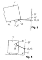
- Office trolley 1 As can be seen in particular from the enlarged schematic Top view of one parked at a parking space 9 Office trolley 1 according to Figure 3 and the schematic side view 4 shows, is on such mobile office furniture 1, for example on a side wall 19 (on which, for example, no door or roller shutter is provided is) an electrical interface device 21 formed with a connection housing 23, in or on which a first electrical connector device 25 is formed.
- the parkable office trolley is 1 am Pitch 9 an electrical connection cable 15 in sufficient Length provided at its free end a second electrical plug connection device 29 is provided.
- the second electrical Plug connection device 29 gripped and in the first electrical connector device on the furniture side 25 can be inserted.
- the im Inside the office car 1 connected Devices via an integrated cable distribution with the building Power grid connected.
- an office trolley can (usually the next day) 1 out of the office car garage 7 and to be rolled to a job.
- an office car 1 according to arrow representation 31 in FIG 2 out of a parking space 9 it may be sagging electrical connection cables 15 tightened up due to the limited length of the electrical connection cable 27 or one in the Usually provided rope or chain-shaped strain relief (which is on the one hand stationary, for example in the wall 35 of the building and on the other hand on the second electrical plug connection device 29) the second Plug connection device 29 from the furniture-side first electrical connector 25 automatically is pulled out.
- the furniture side first electrical connector 25 only exactly horizontal would align it to a misunderstanding of one another lead plug-in connector, with the result that it may pull apart on its own of the two connector halves foiled would.
- connection housing 23 is the electrical Interface device 21 at least about an axis in swiveling, tilting or a certain angular range bendable so that the connector devices align themselves as precisely as possible in the direction of pull automatic decoupling and disconnection, i.e. the pulling apart of the two nested Connector elements is easily supported.
- FIGS. 5 ff The structure required for this is shown in FIGS. 5 ff.
- connection housing 23 is an electrical one Interface device 21 when removed Housing cover 23 'shown.
- connection housing 23 is in plan view according to this Embodiment circular, i.e. designed in a can shape and has a perpendicular to the middle Housing bottom 23 ", i.e. in the embodiment shown perpendicular to the associated furniture wall 41 a pivot axis 43, around which the connection housing 23 is pivotable.
- the top or surface of the furniture wall 41 or the underside of the housing base 23 " form a mounting surface 41 ', referring to the connection housing 23 is assembled.
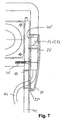
- connection housing 23 comprises one in the middle stuck on the associated furniture wall 41 and for example by means of two screws 45 Axle body 43 'around which the base plate is captive 23 "and thus the connection housing 23 overall in one pivoted angle range discussed below can be.
- first electrical connector 25 is provided, which is usually made of plastic, where in Connection area which preferably consists of plastic Protective cover 49 a first at a sufficient distance Conductor 51, a second conductor 53 and an earth conductor 55 provided.
- the hollow cylinder 59 protrudes through a part-circular recess 65 through, with the opposite ends the part-circular recess 65 in the embodiment shown to the outer circumference of the hollow cylinder 59 are adapted, that is to say designed in the form of a part circle in plan view are.
- These part-circular ends 67 serve as End stops for swiveling the connection housing 23.
- the dashed lines 69 and 69 define each the end position of the swivel or tilt angle.
- the electrical interface device explained can also be trained elsewhere on the furniture trolley, for example on a rear wall, on a top wall or on partition walls accessible from the outside or on the inside Walls or other externally accessible chambers or recording rooms on or in the mobile office furniture 1.
Landscapes
- Connector Housings Or Holding Contact Members (AREA)
- Telephone Set Structure (AREA)
- Legs For Furniture In General (AREA)
- Tables And Desks Characterized By Structural Shape (AREA)
- Selective Calling Equipment (AREA)
Description
- Figur 1 :
- eine schematische perspektivische Darstellung eines verfahrbaren Möbelcontainers mit einer erfindungsgemäß an einer Seitenwand ausgebildeten elektrischen Schnittstelleneinrichtung;
- Figur 2 :
- eine schematische teilweise Draufsicht auf einen Aufbewahrungsort nach Art einer "Mobilmöbel-Garage", in welcher mehrere mobile Büromöbelwagen nebeneinander in einzelnen "Boxen" unter Herstellung einer elektrischen Anschlussverbindung zu einem gebäudeseitigen Stromnetz abstellbar sind;
- Figur 3 :
- eine schematische vergrößerte Detaildarstellung aus Figur 2;
- Figur 4 :
- eine schematische Seitenansicht auf einen im Aufbewahrungsort abgestellten mobilen Bürowagen;
- Figur 5 :
- eine schematische Draufsicht auf die erfindungsgemäß elektrische Schnittstelleneinrichtung bei abgenommenen Gehäusedeckel;
- Figur 6 :
- eine vertikale Schnittdarstellung; und
- Figur 7 :
- eine horizontale Schnittdarstellung.
Claims (12)
- Elektrische Schnittstelleneinrichtung, insbesondere für mobile Möbel, mit folgenden Merkmalen:gekennzeichnet durch die folgenden weiteren Merkmaleeiner elektrischen Steckverbindungseinrichtung (25) die mit einer externer zweiten elektrischen Streckverbindungseinrichtung (29) elektrisch kontakter bar ist,einer Anschlusseinrichtung (23), zum Montieren auf eine Montagefläche, an welcher Anschlusseinrichtung die Steckverbindungseinrichtung (25) ausgebildet oder gehalten ist,die Anschlusseinrichtung (23) ist mit der Steckverbindungseinrichtung (25) zumindest um eine sich senkrecht zur Montagefläche (41') erstreckende Verschwenkachse (43) verschwenkbar, unddie Anschlusseinrichtung (23) umfasst eine Bodenplatte (23"), in welcher eine Ausnehmung (65) zur Zuführung von Anschlusskabeln vorgesehen ist,zur Verschwenkachse (43) versetzt liegend ist ein Kanalstück (59) zur Zuführung von Anschlusskabeln vorgesehen,das Kanalstück (59) durchragt die Ausnehmung (65), die größer bemessen ist als das Kanalstück (59),die Ausnehmung (65) in der Bodenplatte (23") des Anschlussgehäuses (23) ist bogenförmig gestaltet,die gegenüberliegenden Öffnungsenden der bogenförmigen Ausnehmung (65) dienen als Endanschläge (67), die in der jeweiligen Verschwenk-Endlage der Anschlusseinrichtung (23) an dem Kanalstück (59) anschlagen.
- Elektrische Schnittstelleneinrichtung nach Anspruch 1, dadurch gekennzeichnet, dass das Kanalstück (59) hohlzylinderförmig und die Endanschläge (67) der bogenförmigen Ausnehmung (65) in Draufsicht halbkreisförmig gestaltet sind.
- Elektrische Schnittstelleneinrichtung nach Anspruch 1 oder 2, gekennzeichnet durch die folgenden weiteren Merkmale:die Steckverbindungseinrichtung (25) erstreckt sich mit ihrer Steckrichtung radial oder zumindest mit Radialkomponente bezüglich der Verschwenkachse (43), unddie Steckverbindungseinrichtung (25) ist mit ihren elektrischen Leitern oder Kontakten (51, 53, 55) vor ihrer Montagefläche(41) verschwenkbar angeordnet.
- Elektrische Schnittstelleneinrichtung nach Anspruch 1, dadurch gekennzeichnet, dass die Steckverbindungseinrichtung bei Draufsicht quer zur Montagefläche (41'), zumindest mit ihren Leitern oder Steckanschlüssen (51, 53, 55) zu der Öffnung (57), durch welche das zumindest eine Elektrokabel (61) hindurchgeführt ist, versetzt liegt.
- Elektrische Schnittstelleneinrichtung nach einem der Ansprüche 1 bis 4, dadurch gekennzeichnet, dass die elektrischen Leiter (51, 53, 55) der ersten elektrischen Steckverbindungseinrichtung (25), abgesehen von einer seitlichen Schutzumhüllung (49), in Steckrichtung freiliegen.
- Elektrische Schnittstelleneinrichtung nach einem der Ansprüche 1 bis 5, dadurch gekennzeichnet, dass die erste elektrische Steckverbindungseinrichtung (25) hinter einem aufklappbaren, verschiebbaren und/oder entfernbaren Wandabschnitt liegt.
- Elektrische Schnittstelleneinrichtung nach einem der Ansprüche 1 bis 6, dadurch gekennzeichnet, dass die zumindest eine Verschwenkachse (43), um welche die Anschlusseinrichtung (23) verschwenkbar ist, senkrecht zu der Montagefläche(41') ausgerichtet verläuft.
- Elektrische Schnittstelleneinrichtung nach einem der Ansprüche 1 bis 7, dadurch gekennzeichnet, dass die Anschlusseinrichtung (23) noch um eine weitere Verschwenkachse (71) verschwenkbar ist.
- Elektrische Schnittstelleneinrichtung nach Anspruch 8, dadurch gekennzeichnet, dass die zumindest beiden Verschwenkachsen (43, 71), um welche die erste elektrische Steckverbindungseinrichtung (25) zumindest in einem geringen Winkelbereich verschwenkbar sind, senkrecht zueinander liegen.
- Elektrische Schnittstelleneinrichtung nach einem der Ansprüche 1 bis 9, dadurch gekennzeichnet, dass die Steckverbindungseinrichtung (25) auf der Bodenplatte (23") sitzt oder ausgebildet ist.
- Elektrische Schnittstelleneinrichtung nach einem der Ansprüche 1 bis 10, dadurch gekennzeichnet, dass die Anschlusseinrichtung (23) einen feststehend montierbaren Achskörper (43') unter Bildung der Verschwenkachse (43) umfasst, um welchen herum die Anschlusseinrichtung (23), insbesondere ein Anschlussgehäuse (23), verschwenkbar ist.
- Elektrische Schnittstelleneinrichtung nach einem der Ansprüche 1 bis 11, dadurch gekennzeichnet, dass das Kanalstück (59) unverschwenkbar ist.
Applications Claiming Priority (2)
| Application Number | Priority Date | Filing Date | Title |
|---|---|---|---|
| DE19938860A DE19938860C1 (de) | 1999-08-17 | 1999-08-17 | Elektrische Schnittstelleneinrichtung insbesondere für mobile Büromöbel |
| DE19938860 | 1999-08-17 |
Publications (2)
| Publication Number | Publication Date |
|---|---|
| EP1079477A1 EP1079477A1 (de) | 2001-02-28 |
| EP1079477B1 true EP1079477B1 (de) | 2002-11-20 |
Family
ID=7918593
Family Applications (1)
| Application Number | Title | Priority Date | Filing Date |
|---|---|---|---|
| EP00117168A Expired - Lifetime EP1079477B1 (de) | 1999-08-17 | 2000-08-10 | Elektrische Schnittstelleneinrichtung, insbesondere für mobile Büromöbel |
Country Status (4)
| Country | Link |
|---|---|
| EP (1) | EP1079477B1 (de) |
| AT (1) | ATE228275T1 (de) |
| DE (2) | DE19938860C1 (de) |
| ES (1) | ES2186609T3 (de) |
Family Cites Families (6)
| Publication number | Priority date | Publication date | Assignee | Title |
|---|---|---|---|---|
| DE2623145A1 (de) * | 1976-05-22 | 1977-12-01 | Bosch Gmbh Robert | Steckverbindung |
| DE3534457A1 (de) * | 1985-09-27 | 1987-04-02 | Schwoerer Artur | Steckerleiste |
| DE29509249U1 (de) * | 1994-12-01 | 1996-03-28 | Interconnectron Gesellschaft für industrielle Steckverbindungen mbH, 94469 Deggendorf | Winkelförmiger Steckträger |
| DE19542359C2 (de) * | 1995-11-14 | 2002-06-27 | Abb Patent Gmbh | Dreh- und schwenkbare UP-Steckdose |
| DE19547879C2 (de) * | 1995-12-21 | 2002-11-14 | Abb Patent Gmbh | Steckdose |
| DE29710984U1 (de) * | 1997-06-24 | 1997-08-21 | Festo Kg, 73734 Esslingen | Elektrische Steckverbindungseinrichtung |
-
1999
- 1999-08-17 DE DE19938860A patent/DE19938860C1/de not_active Expired - Fee Related
-
2000
- 2000-08-10 ES ES00117168T patent/ES2186609T3/es not_active Expired - Lifetime
- 2000-08-10 EP EP00117168A patent/EP1079477B1/de not_active Expired - Lifetime
- 2000-08-10 DE DE50000782T patent/DE50000782D1/de not_active Expired - Lifetime
- 2000-08-10 AT AT00117168T patent/ATE228275T1/de not_active IP Right Cessation
Also Published As
| Publication number | Publication date |
|---|---|
| DE50000782D1 (de) | 2003-01-02 |
| ATE228275T1 (de) | 2002-12-15 |
| EP1079477A1 (de) | 2001-02-28 |
| ES2186609T3 (es) | 2003-05-16 |
| DE19938860C1 (de) | 2001-03-15 |
Similar Documents
| Publication | Publication Date | Title |
|---|---|---|
| EP2170123B1 (de) | Etagenträgersystem | |
| EP2058911B1 (de) | Medizinische Versorgungseinheit zur Stromversorgung und Datenübertragung bei medizinischen Apparaten | |
| EP2220965A2 (de) | Präsentationssystem mit Trägerprofilschiene | |
| DE2911065A1 (de) | Wandsystem | |
| EP3711138B1 (de) | Ladestation für elektrofahrzeuge | |
| EP2328255A1 (de) | Ladevorrichtung mit schwenkbarer Geräteablage | |
| DE202008007098U1 (de) | Steckdose | |
| DE4008340A1 (de) | Schutzgehaeuse fuer optische geraete | |
| DE102017109985B3 (de) | Leitungskabel und Energieversorgungssystem | |
| WO2006042644A1 (de) | Vorrichtung zur aufnahme mindestens eines steckdoseneinsatzes | |
| EP1079477B1 (de) | Elektrische Schnittstelleneinrichtung, insbesondere für mobile Büromöbel | |
| EP0484811A1 (de) | Elektrischer Schaltschrank für Niederspannungsanlagen | |
| DE69419972T2 (de) | Distributionskanal einschliesslich Terminalanordnungen | |
| DE102018115123A1 (de) | Wandladestation zum Laden eines Elektrofahrzeugs | |
| EP1588541A1 (de) | Mobile mehrfachsteckdose mit ablagetisch | |
| EP2007251A1 (de) | Möbel | |
| DE3101976C2 (de) | Mit elektrischen Geräten bestückbarer Schreibtisch | |
| AT409686B (de) | Stromschienen-element, adapterfixteil, adapterdrehteil sowie steckdosenadapter | |
| DE9415823U1 (de) | Elektronikeinbaugehäuse | |
| DE10113528A1 (de) | Kabelführungsmodul und Verwendung desselben | |
| DE10351969A1 (de) | Aufnahme für elektrische Kabel | |
| EP0174500A1 (de) | Mobile Wandung | |
| AT11847U1 (de) | Vorrichtung zum anschluss elektrischer installationsgeräte | |
| DE20000561U1 (de) | Unterflurgerätebecher | |
| DE202004005596U1 (de) | Steckdosenblock |
Legal Events
| Date | Code | Title | Description |
|---|---|---|---|
| PUAI | Public reference made under article 153(3) epc to a published international application that has entered the european phase |
Free format text: ORIGINAL CODE: 0009012 |
|
| AK | Designated contracting states |
Kind code of ref document: A1 Designated state(s): AT BE CH CY DE DK ES FI FR GB GR IE IT LI LU MC NL PT SE |
|
| AX | Request for extension of the european patent |
Free format text: AL;LT;LV;MK;RO;SI |
|
| 17P | Request for examination filed |
Effective date: 20010222 |
|
| 17Q | First examination report despatched |
Effective date: 20010507 |
|
| AKX | Designation fees paid |
Free format text: AT BE CH CY DE DK ES FI FR GB GR IE IT LI LU MC NL PT SE |
|
| GRAG | Despatch of communication of intention to grant |
Free format text: ORIGINAL CODE: EPIDOS AGRA |
|
| GRAG | Despatch of communication of intention to grant |
Free format text: ORIGINAL CODE: EPIDOS AGRA |
|
| GRAH | Despatch of communication of intention to grant a patent |
Free format text: ORIGINAL CODE: EPIDOS IGRA |
|
| RAP1 | Party data changed (applicant data changed or rights of an application transferred) |
Owner name: STEELCASE WERNDL AKTIENGESELLSCHAFT |
|
| GRAH | Despatch of communication of intention to grant a patent |
Free format text: ORIGINAL CODE: EPIDOS IGRA |
|
| GRAA | (expected) grant |
Free format text: ORIGINAL CODE: 0009210 |
|
| AK | Designated contracting states |
Kind code of ref document: B1 Designated state(s): AT BE CH CY DE DK ES FI FR GB GR IE IT LI LU MC NL PT SE |
|
| PG25 | Lapsed in a contracting state [announced via postgrant information from national office to epo] |
Ref country code: GR Free format text: LAPSE BECAUSE OF FAILURE TO SUBMIT A TRANSLATION OF THE DESCRIPTION OR TO PAY THE FEE WITHIN THE PRESCRIBED TIME-LIMIT Effective date: 20021120 Ref country code: IE Free format text: LAPSE BECAUSE OF FAILURE TO SUBMIT A TRANSLATION OF THE DESCRIPTION OR TO PAY THE FEE WITHIN THE PRESCRIBED TIME-LIMIT Effective date: 20021120 Ref country code: NL Free format text: LAPSE BECAUSE OF FAILURE TO SUBMIT A TRANSLATION OF THE DESCRIPTION OR TO PAY THE FEE WITHIN THE PRESCRIBED TIME-LIMIT Effective date: 20021120 Ref country code: FI Free format text: LAPSE BECAUSE OF FAILURE TO SUBMIT A TRANSLATION OF THE DESCRIPTION OR TO PAY THE FEE WITHIN THE PRESCRIBED TIME-LIMIT Effective date: 20021120 |
|
| REF | Corresponds to: |
Ref document number: 228275 Country of ref document: AT Date of ref document: 20021215 Kind code of ref document: T |
|
| REG | Reference to a national code |
Ref country code: GB Ref legal event code: FG4D Free format text: NOT ENGLISH |
|
| REG | Reference to a national code |
Ref country code: CH Ref legal event code: EP |
|
| GBT | Gb: translation of ep patent filed (gb section 77(6)(a)/1977) |
Effective date: 20021120 |
|
| REG | Reference to a national code |
Ref country code: IE Ref legal event code: FG4D Free format text: GERMAN |
|
| REF | Corresponds to: |
Ref document number: 50000782 Country of ref document: DE Date of ref document: 20030102 |
|
| PG25 | Lapsed in a contracting state [announced via postgrant information from national office to epo] |
Ref country code: SE Free format text: LAPSE BECAUSE OF FAILURE TO SUBMIT A TRANSLATION OF THE DESCRIPTION OR TO PAY THE FEE WITHIN THE PRESCRIBED TIME-LIMIT Effective date: 20030220 Ref country code: PT Free format text: LAPSE BECAUSE OF FAILURE TO SUBMIT A TRANSLATION OF THE DESCRIPTION OR TO PAY THE FEE WITHIN THE PRESCRIBED TIME-LIMIT Effective date: 20030220 Ref country code: DK Free format text: LAPSE BECAUSE OF FAILURE TO SUBMIT A TRANSLATION OF THE DESCRIPTION OR TO PAY THE FEE WITHIN THE PRESCRIBED TIME-LIMIT Effective date: 20030220 |
|
| NLV1 | Nl: lapsed or annulled due to failure to fulfill the requirements of art. 29p and 29m of the patents act | ||
| ET | Fr: translation filed | ||
| REG | Reference to a national code |
Ref country code: ES Ref legal event code: FG2A Ref document number: 2186609 Country of ref document: ES Kind code of ref document: T3 |
|
| REG | Reference to a national code |
Ref country code: IE Ref legal event code: FD4D Ref document number: 1079477E Country of ref document: IE |
|
| PG25 | Lapsed in a contracting state [announced via postgrant information from national office to epo] |
Ref country code: AT Free format text: LAPSE BECAUSE OF NON-PAYMENT OF DUE FEES Effective date: 20030810 Ref country code: LU Free format text: LAPSE BECAUSE OF NON-PAYMENT OF DUE FEES Effective date: 20030810 Ref country code: CY Free format text: LAPSE BECAUSE OF FAILURE TO SUBMIT A TRANSLATION OF THE DESCRIPTION OR TO PAY THE FEE WITHIN THE PRESCRIBED TIME-LIMIT Effective date: 20030810 |
|
| PG25 | Lapsed in a contracting state [announced via postgrant information from national office to epo] |
Ref country code: BE Free format text: LAPSE BECAUSE OF NON-PAYMENT OF DUE FEES Effective date: 20030831 Ref country code: MC Free format text: LAPSE BECAUSE OF NON-PAYMENT OF DUE FEES Effective date: 20030831 |
|
| PLBE | No opposition filed within time limit |
Free format text: ORIGINAL CODE: 0009261 |
|
| STAA | Information on the status of an ep patent application or granted ep patent |
Free format text: STATUS: NO OPPOSITION FILED WITHIN TIME LIMIT |
|
| 26N | No opposition filed |
Effective date: 20030821 |
|
| BERE | Be: lapsed |
Owner name: *STEELCASE WERNDL A.G. Effective date: 20030831 |
|
| PG25 | Lapsed in a contracting state [announced via postgrant information from national office to epo] |
Ref country code: CH Free format text: LAPSE BECAUSE OF NON-PAYMENT OF DUE FEES Effective date: 20040831 Ref country code: LI Free format text: LAPSE BECAUSE OF NON-PAYMENT OF DUE FEES Effective date: 20040831 |
|
| REG | Reference to a national code |
Ref country code: CH Ref legal event code: PL |
|
| PGFP | Annual fee paid to national office [announced via postgrant information from national office to epo] |
Ref country code: ES Payment date: 20100825 Year of fee payment: 11 |
|
| PGFP | Annual fee paid to national office [announced via postgrant information from national office to epo] |
Ref country code: IT Payment date: 20100823 Year of fee payment: 11 Ref country code: DE Payment date: 20100823 Year of fee payment: 11 Ref country code: FR Payment date: 20100901 Year of fee payment: 11 |
|
| PGFP | Annual fee paid to national office [announced via postgrant information from national office to epo] |
Ref country code: GB Payment date: 20100819 Year of fee payment: 11 |
|
| GBPC | Gb: european patent ceased through non-payment of renewal fee |
Effective date: 20110810 |
|
| REG | Reference to a national code |
Ref country code: FR Ref legal event code: ST Effective date: 20120430 |
|
| PG25 | Lapsed in a contracting state [announced via postgrant information from national office to epo] |
Ref country code: IT Free format text: LAPSE BECAUSE OF NON-PAYMENT OF DUE FEES Effective date: 20110810 |
|
| REG | Reference to a national code |
Ref country code: DE Ref legal event code: R119 Ref document number: 50000782 Country of ref document: DE Effective date: 20120301 |
|
| PG25 | Lapsed in a contracting state [announced via postgrant information from national office to epo] |
Ref country code: FR Free format text: LAPSE BECAUSE OF NON-PAYMENT OF DUE FEES Effective date: 20110831 Ref country code: GB Free format text: LAPSE BECAUSE OF NON-PAYMENT OF DUE FEES Effective date: 20110810 |
|
| PG25 | Lapsed in a contracting state [announced via postgrant information from national office to epo] |
Ref country code: DE Free format text: LAPSE BECAUSE OF NON-PAYMENT OF DUE FEES Effective date: 20120301 |
|
| REG | Reference to a national code |
Ref country code: ES Ref legal event code: FD2A Effective date: 20131030 |
|
| PG25 | Lapsed in a contracting state [announced via postgrant information from national office to epo] |
Ref country code: ES Free format text: LAPSE BECAUSE OF NON-PAYMENT OF DUE FEES Effective date: 20110811 |