EP1079578A2 - Datenzuweisung in Mehrträgersystemen - Google Patents
Datenzuweisung in Mehrträgersystemen Download PDFInfo
- Publication number
- EP1079578A2 EP1079578A2 EP00117628A EP00117628A EP1079578A2 EP 1079578 A2 EP1079578 A2 EP 1079578A2 EP 00117628 A EP00117628 A EP 00117628A EP 00117628 A EP00117628 A EP 00117628A EP 1079578 A2 EP1079578 A2 EP 1079578A2
- Authority
- EP
- European Patent Office
- Prior art keywords
- communication channel
- data
- communication
- transmission
- channel
- Prior art date
- Legal status (The legal status is an assumption and is not a legal conclusion. Google has not performed a legal analysis and makes no representation as to the accuracy of the status listed.)
- Withdrawn
Links
- 238000004891 communication Methods 0.000 claims abstract description 74
- 238000000034 method Methods 0.000 claims description 58
- 230000005540 biological transmission Effects 0.000 claims description 29
- 238000001228 spectrum Methods 0.000 claims description 11
- 238000012545 processing Methods 0.000 claims description 9
- 238000011144 upstream manufacturing Methods 0.000 claims description 7
- 238000001514 detection method Methods 0.000 claims description 2
- 230000004044 response Effects 0.000 claims description 2
- 230000000977 initiatory effect Effects 0.000 claims 1
- 238000012549 training Methods 0.000 description 19
- 239000000969 carrier Substances 0.000 description 16
- 238000004458 analytical method Methods 0.000 description 8
- 230000008569 process Effects 0.000 description 7
- 230000000694 effects Effects 0.000 description 4
- 230000002829 reductive effect Effects 0.000 description 4
- 239000000835 fiber Substances 0.000 description 3
- 230000002452 interceptive effect Effects 0.000 description 3
- 230000004913 activation Effects 0.000 description 2
- 230000003139 buffering effect Effects 0.000 description 2
- 238000012937 correction Methods 0.000 description 2
- 238000010586 diagram Methods 0.000 description 2
- 238000005259 measurement Methods 0.000 description 2
- 238000012935 Averaging Methods 0.000 description 1
- 230000003466 anti-cipated effect Effects 0.000 description 1
- 230000002238 attenuated effect Effects 0.000 description 1
- 230000009286 beneficial effect Effects 0.000 description 1
- 230000008901 benefit Effects 0.000 description 1
- 238000005516 engineering process Methods 0.000 description 1
- 238000005429 filling process Methods 0.000 description 1
- 238000007429 general method Methods 0.000 description 1
- 230000036039 immunity Effects 0.000 description 1
- 238000009434 installation Methods 0.000 description 1
- 230000000670 limiting effect Effects 0.000 description 1
- 238000012986 modification Methods 0.000 description 1
- 230000004048 modification Effects 0.000 description 1
- 238000005457 optimization Methods 0.000 description 1
- 230000000135 prohibitive effect Effects 0.000 description 1
- 230000009467 reduction Effects 0.000 description 1
Images




Classifications
-
- H—ELECTRICITY
- H04—ELECTRIC COMMUNICATION TECHNIQUE
- H04L—TRANSMISSION OF DIGITAL INFORMATION, e.g. TELEGRAPHIC COMMUNICATION
- H04L5/00—Arrangements affording multiple use of the transmission path
- H04L5/003—Arrangements for allocating sub-channels of the transmission path
- H04L5/0058—Allocation criteria
- H04L5/0064—Rate requirement of the data, e.g. scalable bandwidth, data priority
-
- H—ELECTRICITY
- H04—ELECTRIC COMMUNICATION TECHNIQUE
- H04L—TRANSMISSION OF DIGITAL INFORMATION, e.g. TELEGRAPHIC COMMUNICATION
- H04L5/00—Arrangements affording multiple use of the transmission path
- H04L5/003—Arrangements for allocating sub-channels of the transmission path
- H04L5/0044—Allocation of payload; Allocation of data channels, e.g. PDSCH or PUSCH
- H04L5/0046—Determination of the number of bits transmitted on different sub-channels
-
- H—ELECTRICITY
- H04—ELECTRIC COMMUNICATION TECHNIQUE
- H04L—TRANSMISSION OF DIGITAL INFORMATION, e.g. TELEGRAPHIC COMMUNICATION
- H04L5/00—Arrangements affording multiple use of the transmission path
- H04L5/003—Arrangements for allocating sub-channels of the transmission path
- H04L5/0058—Allocation criteria
- H04L5/006—Quality of the received signal, e.g. BER, SNR, water filling
-
- H—ELECTRICITY
- H04—ELECTRIC COMMUNICATION TECHNIQUE
- H04L—TRANSMISSION OF DIGITAL INFORMATION, e.g. TELEGRAPHIC COMMUNICATION
- H04L5/00—Arrangements affording multiple use of the transmission path
- H04L5/02—Channels characterised by the type of signal
- H04L5/06—Channels characterised by the type of signal the signals being represented by different frequencies
-
- H—ELECTRICITY
- H04—ELECTRIC COMMUNICATION TECHNIQUE
- H04L—TRANSMISSION OF DIGITAL INFORMATION, e.g. TELEGRAPHIC COMMUNICATION
- H04L5/00—Arrangements affording multiple use of the transmission path
- H04L5/14—Two-way operation using the same type of signal, i.e. duplex
- H04L5/143—Two-way operation using the same type of signal, i.e. duplex for modulated signals
-
- H—ELECTRICITY
- H04—ELECTRIC COMMUNICATION TECHNIQUE
- H04L—TRANSMISSION OF DIGITAL INFORMATION, e.g. TELEGRAPHIC COMMUNICATION
- H04L5/00—Arrangements affording multiple use of the transmission path
- H04L5/0001—Arrangements for dividing the transmission path
- H04L5/0003—Two-dimensional division
- H04L5/0005—Time-frequency
- H04L5/0007—Time-frequency the frequencies being orthogonal, e.g. OFDM(A) or DMT
Definitions
- This invention relates generally to communication systems and more specifically to methods and apparatus for use with overlap-enabled communication systems.
- ADSL Asymmetrical Digital Subscriber Line
- Discrete Multi-Toned is a multi-carrier technique that divides the available bandwidth of a communications channel such as a twisted pair connection into a number of frequency sub-channels. These sub-channels are also referred to as frequency bins or carriers.
- the DMT technique has been adopted by the ANSI T1E1.4 (ADSL) committee for use in ADSL systems.
- ADSL ANSI T1E1.4
- DMT is used to generate 250 separate 4.3125 kHz sub-channels from 26 kHz to 1.1 MHz for downstream transmission to the end user, and 25 sub-channels from 26 kHz to 138 kHz for upstream transmission by the end user.
- Each bin is allocated a number of bits to send with each transmission.
- the number of bits allocated to an ADSL system are 0, and 2-15 bits.
- an initialization process Prior to transmitting real-time data with an ADSL system, an initialization process occurs. During a first portion of the initialization process, an activation and acknowledgment step occurs. It is during this step that a transmit activation tone is generated following power-up of the ADSL system.
- Transceiver training is the next step of the initialization process. During transceiver training, the equalization filters of the ADSL system are trained and system synchronization is achieved. Next, channel analysis and exchange are performed as part of the initialization processes. During the channel analysis and exchange, the Signal to Noise Ratio (SNR) of the channels is determined, and bit loading configuration of the bins and other configuration information is transferred.
- SNR Signal to Noise Ratio
- Another issue of transmitting power on unused bins is that as a carrier's signal is attenuated over long line distances, there is a point where data cannot be transmitted with a desired certainty. When this occurs, the bit allocation capacity of the bad bin is set to zero, however, under proposed implementations of the specification, its transmit power remains allocated to the now unused bin. Therefore, there is a high cost in power even when there is not a high data rate.
- Another issue with the ADSL specification is that crosstalk interference occurs when signals are being transmitted at similar frequencies on adjacent line.
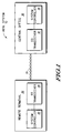
- FIG. 1 illustrates an ADSL system 10.
- the ADSL system 10 comprises a remote terminal 20, and a central office 30 connected by a twisted pair transmission media.
- the remote terminal 20 and central office 30 each comprise a system controller 22 and 34, respectively.
- the remote terminal 20 and central office 30 respectively comprise a transceiver 24 and 32.
- the transceiver may include a processor unit, various filters, such as digital filters or analog filters, and a line driver in communication with a communication channel.
- the filters and line driver may be dynamically configured by the processing unit to allow for communication over various selected frequency regions of the communication channel.
- the ADSL system 10 is capable of implementing the present invention.
- the central office 30 transmits downstream data across the transmission media 15 to the remote terminal 20.
- the data is received at the remote terminal 20 by the transceiver 24, which provides the received data to the system controller 22 for further processing.
- the upstream data would be transmitted from the remote terminal 20, across the transmission media 15, and received by the central office transceiver 32, which provides the data to the system controller 34.
- FIG. 2 illustrates an SNR reference table for use within the ADSL system 10.
- the SNR reference table indicates an SNRref value, which is the SNR needed for a bin to transmit a specific number of bits at a specific Bit Error Rate (BER).
- BER Bit Error Rate
- a bin which is determined to have an SNR of 30 would be able to transmit seven bits of data.
- the values of SNR reference table will vary depending upon the type of error correction used, if any. For example, the use of error correction could reduce each SNRref value in FIG. 2 by three. This reduction would allow a bin having a SNR of 30 to transmit eight bits.
- the SNR reference table will be empirically derived, but can also be derived based upon simulated or theoretical results.
- FIG. 3 illustrates a method for implementing the present invention. While the specific embodiment will address a specific DMT implementation, it is to be understood that the present invention applies to any DMT implementation.
- an analysis of an ADSL channel is performed.
- the channel analysis step 311 would return a signal-to-noise ratio (SNR) for a channel in an initial state.
- SNR signal-to-noise ratio
- the channel analysis step 311 of FIG. 3 is performed as part of the initialization process.
- other implementations where the steps of FIG. 3 are performed during real time operation are anticipated by the present invention.
- the data capacity of each bin is calculated.
- the data capacity is calculated based upon the SNR of a carrier, as determined in step 311, and the SNR reference table of FIG. 2.
- the data capacity can be determined by identifying, for a given SNR reference table, the maximum number of bits that can be transmitted. For example, according to the table of FIG. 2, the maximum number of bits that could be allocated to a bin having an SNR of 32 is seven bits.
- the carriers or bins are sorted from greatest capacity to least capacity.
- the data rate to be transmitted is allocated beginning with the carrier(s) with the greatest capacity and proceeding to the carrier(s) with the least capacity.
- the data capacity is allocated until the specified data rate is achieved.
- the power on the unused carriers is reduced in order to minimize the power used to transmit a specified amount of information.
- the power will be reduced by at least an order of magnitude of the power of a used bin. This is advantageous over the prior art which has required each channel to maintain a nominal amount of power whether it is used or unused. By reducing power to unused bins, an optimal amount of power dissipation is possible.
- FIG. 4 illustrates a different embodiment of the present invention.
- a subset carrier X is specified.
- the subset X will generally represent carriers which are to be preferred or avoided during the bit loading allocation process.
- the subset X is then weighted.
- the weighting can be explicit, whereby a weighting value is specified by a user, or implicit, whereby the system would have a default weighting for the subset X. For example, the subset X could implicitly be heavily weighted.
- the function of the weighting will be discussed with reference to step 415.
- step 412 a channel analysis is performed on each carrier of set N.
- the channel analysis of step 412 is performed in the same manner as the channel analysis of step 311 of FIG. 3, as previously discussed.
- step 413 the bit loading capacity for each bin in carrier set N is calculated. This step is analogous to step 312 of FIG. 3.
- step 414 the carriers of set N that are not in set X are sorted from greatest bit loading capacity to least bit loading capacity to form a sorted set of carriers.
- This step is analogous in function to step 313 of FIG. 3, except that it is performed on a subset of the set.
- the carriers in set X are also sorted from greatest bit loading capacity to least bit loading capacity to for another sorted set.
- the set X need not be sorted.
- the bins associated with carrier subset X are inserted or excluded from the sorted set of carriers.
- the set would be positioned in the sorted set before, or after, bins meeting some predefined criteria. For example, heavily weighted bins could be positioned before the bins with the greatest capacity. In another embodiment, the heavily weighted bins could be positioned between bins having a capacity of ten bits, and bins having a capacity of nine bits. Generally, a heavily weighted set is inserted with bins having significant bit allocation capacity. In one embodiment, where 15 bits is the maximum loading for a bin, a heavily weighted set would generally be inserted at or above the 7 bit allocation level.
- bins of set X are implicitly lightly weighted, they could be excluded from the sorted list entirely, inserted after the bins with the least bit loading capacity, or inserted between bins having a specified loading level.
- a lightly weighted set is inserted with bins having low bit allocation capacity.
- 15 bits is the maximum loading for a bin
- a heavily weighted set would generally be inserted at or above the 7 bit allocation level.
- the number of bits needed to support a specified data rate are allocated to the bins based upon the sorted order of the set. For example, assuming the set X is inserted between bins having loading capacity of 13 and 14 bits. The allocation would begin with a bin, not in set X, having 15 bits of loading capacity. Once the first bin was assigned 15 bits, another bin, not in set X, having 15 bits of capacity would be assigned 15 bits, and so on until all 15 bit bins are fully assigned. Next, all 14 bit bins, not in set X would be filled in a similar manner. Next, the bits of set X would be filled prior to the loading of any 13 bit capacity bin which is not in set X. Subsequent to each bin of set X being filled, the filling process would continue with the 13 bit capacity bins.
- FIG. 5 illustrates another embodiment of the present invention whereby crosstalk between adjacent lines can be reduced.
- a subset of carriers X1 is specified for a first line card.
- the flow of FIG. 4 is applied to the subset X1. This in effect minimized the number of carriers line card 2 needs to drive in order to support a specific data rate.
- a subset of substantially non-overlapping carriers X2 is specified for a first line card.
- the sets X1 and X2 would be mutually exclusive in that they would attempt to allocate the data capacity to bins operating at different frequencies.
- the sets X1 and X2 would be chosen to buffer used bins in separate line cards from each other. For example, if set X1 specified bins 1-10 as bins to be filled first, set X2 would indicate bins 12-21 as bins to be filled first. To the extent the bit loading capacity could be allocated within the specified bins, there would be an unused bin, bin 11, buffering the frequency range of set X1 and X2. This buffering allows for greater immunity to cross talk.
- step X2 the method of figure 4 is applied in order to optimize power of the system.
- step 505 data transmission occurs, allowing for optimization of power dissipation and limiting crosstalk among adjacent lines.
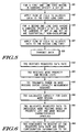
- FIG. 6 illustrates a method of allocating data in a communication system.
- TR2 receives a requested data rate.
- TR2 receives at least one mode priority and region list.
- the data rate, mode priority, and region lists may be user inputs received by TR2, may be received by a central office transceiver (TR1) and forwarded to TR2, or may be fixed.
- TR1 may be user inputs received by TR2, may be received by a central office transceiver (TR1) and forwarded to TR2, or may be fixed.
- TR1 central office transceiver
- the region list may separate the total usable bandwidth of a communication channel into individual frequency sub-bands called regions.
- Three exemplary regions are a POTS (Plain Old Telephone System) region, an overlap region, and a non-overlap region as shown in FIG. 7.
- the priority list includes relative priorities of the regions.
- TR1 transmits training sequences over all carriers in multiple regions of the communication channel during a capacity measurement sequence so that TR2 can calculate the capacity for each region during step 640.
- the multiple regions may include, for example, the overlapped region and the non-overlapped region (e.g., an FDM full or FDM lite region).
- the POTS region may also be included.
- TR2 allocates requested data to individual mode regions based on the priority list and the mode region characteristics (discussed hereinafter with reference to FIGs. 7, 9 and 10).
- TR2 configures itself to receive at the requested data rate and sends configuration information to TR1 to appropriately configure TR1's transmitter.
- FIG. 8 illustrates a method of allocating data in a communication system.
- a remote terminal transceiver receives a requested data rate.
- TR2 receives mode priority and region lists. The data rate, mode priority, and region lists, for example, may be user inputs received by TR2, or may be received by a central office transceiver (TR1) and forwarded to TR2, or may be fixed.
- TR1 transmits training sequences in multiple regions during a capacity measurement sequence so that TR2 can calculate the capacity for each region during step 840.
- TR2 sends the maximum capacity information for each region to TR1.
- TR2 receives a new requested data rate and a new priority list.
- TR2 allocates requested data to individual mode regions based on the priority list and the mode region characteristics (discussed hereinafter with reference to FIGs. 7, 9 and 10). Steps 810 and 820 are optional. If steps 810 and 820 are used, TR1 may wait until step 860 to send the first requested data rate, priority list and region list after TR2 sends the capacity for each region to TR1.
- a particular method of allocating data is illustrated.
- characteristics of a communication channel are detected, at 902. Exemplary characteristics include capacity, power detection of a channel, channel length, noise, geography and user input.
- a data carrying method or region is selected. The method or region may be either an overlapped or non-overlapped method or region.
- data is communicated over the channel using the selected method, at 906.
- communication data to be transmitted may be allocated to particular channels in a flexible and configurable manner.
- limited communication resources such as particular frequency bins within an ADSL system, may be used efficiently.
- FIG. 7 a general diagram that illustrates transmit power versus frequency for an overlap-enabled communication system is shown.
- the communication channel is subdivided into separate modes or frequency regions, including a POTS region 710, an overlapped region 708, and a frequency division multiplexed (FDM) full rate region 706.
- These frequency regions form the full spectrum for a full rate ADSL spectrum 702.
- a POTS region 716 For a G.lite spectrum 704 implementation, there is a POTS region 716, an overlap region 714, and an FDM lite region 712.
- the frequency regions have been prioritized in a particular illustrative embodiment in the order P1, P2 and P3 as shown.
- FDM 706 is first priority for allocation
- overlapped region 708 has second priority
- POTS region 710 may be used and has third priority.
- data may be more efficiently allocated and communicated over an ADSL system.
- the priority scheme for allocating data for different regions is useful for customizing training sequences based on user input, channel characteristics or other desired parameters.
- a desired transmission data rate is compared to the available non-overlapped capacity. If the data rate exceeds the non-overlapped capacity, then processing continues to step 1006 where the non-overlapped region is filled to its capacity. Next, in this scenario, the remaining desired capacity which is equal to the desired data rate less the non-overlapped capacity is determined, at 1008. The remainder is then allocated to an overlapped region of the frequency spectrum, at step 1010. However, where the data rate is not less than the non-overlapped capacity, then the data rate is allocated only within the non-overlapped region, at step 1004.
- data capacity is allocated as a first priority to non-overlapped regions (e.g., the FDM full or FDM lite regions) before being allocated to overlapped regions (e.g., an upstream region).
- non-overlapped regions e.g., the FDM full or FDM lite regions
- overlapped regions e.g., an upstream region
- a first transmitter TR1 receives mode priority and region list, at step 1102.
- the priority and region list may either be fixed, may be determined from another transceiver via a message, or may be determined by a user and in this case would be user selectable.
- An example of a mode priority and region list would include a non-overlapped region, an analog POTS region and an overlapped region.
- An example priority scheme may have the non-overlapped region having priority over the overlapped region, and both non-overlapped and overlapped having priority of using the analog POTS region.
- TR1 identifies channel characteristics of a communication channel, such as the channels line length, noise, geography or other user input, at 1104.
- the particular channel characteristics may either be measured, predetermined or received from another transceiver or user.
- the first transmitter TR1 then configures a training sequence for the channel based on the channel characteristics and based on the mode priority list, at 1106.
- a more specific method for performing the training sequence is illustrated in FIG. 12.
- the training sequence is transmitted by TR1 over the channel, at 1108.
- a benefit of the illustrated method of allocating data in the manner shown in FIG. 11, is the flexibility in adapting to priorities and channel characteristics.
- training sequence due to geography
- a system which is sold into two different markets, such as the United States and Europe may conform with two different industry requirements by making a selection of training sequence as a function of geography.
- training sequence is based on line length
- different methods of training and transmitting data may be used as a function of the particular length of line between the carrier equipment and the end user.
- a channel length for a communication channel is determined at 1202.
- One method of determining the line length is to measure received power from a far end transceiver and compare the received power level with a predetermined power to line-length table. Additionally, noise can be factored out by averaging received data.
- the line length may also be received from an external source.
- the line length is compared to a threshold, at decision step 1204. The threshold may be either user input, predetermined or otherwise empirically determined. If the line length exceeds the threshold, then the training sequence is configured using overlapped regions of the frequency spectrum.
- the training sequence is configured without use of the overlapped region, at 1206.
- the line length is used as a decision variable to determine when overlapped regions need to be used when configuring training sequences for subsequent data allocation and communication.
- FIG. 13 an alternative method of allocating data as a function of line length is shown.
- the line length is determined, at 1302.
- the line length is compared to a threshold, at 1304. Where the line length exceeds the threshold, the training sequence is configured without use of a high frequency region, at 1308. Where the line length does not exceed the threshold, the training sequence is configured to use the high frequency region, at 1306.
- the training sequence For communication channels with a long line length, it has been determined that the high frequency regions are not as helpful in gaining additional capacity, and by configuring a training sequence without using such high frequency regions, the overall up link and down link system may be improved.
Landscapes
- Engineering & Computer Science (AREA)
- Signal Processing (AREA)
- Computer Networks & Wireless Communication (AREA)
- Quality & Reliability (AREA)
- Telephonic Communication Services (AREA)
- Communication Control (AREA)
Applications Claiming Priority (2)
| Application Number | Priority Date | Filing Date | Title |
|---|---|---|---|
| US37908199A | 1999-08-23 | 1999-08-23 | |
| US379081 | 1999-08-23 |
Publications (2)
| Publication Number | Publication Date |
|---|---|
| EP1079578A2 true EP1079578A2 (de) | 2001-02-28 |
| EP1079578A3 EP1079578A3 (de) | 2001-11-07 |
Family
ID=23495735
Family Applications (1)
| Application Number | Title | Priority Date | Filing Date |
|---|---|---|---|
| EP00117628A Withdrawn EP1079578A3 (de) | 1999-08-23 | 2000-08-16 | Datenzuweisung in Mehrträgersystemen |
Country Status (3)
| Country | Link |
|---|---|
| US (1) | US7830855B2 (de) |
| EP (1) | EP1079578A3 (de) |
| JP (1) | JP4615684B2 (de) |
Cited By (10)
| Publication number | Priority date | Publication date | Assignee | Title |
|---|---|---|---|---|
| EP1303073A1 (de) * | 2001-08-06 | 2003-04-16 | Broadcom Corporation | Auswahl der Pseudozufallssequenz in Modemkommunikation |
| WO2003052987A3 (en) * | 2001-12-17 | 2004-01-29 | Optinel Systems Inc | Efficient and scalable data transport system for dwdm cable tv networks |
| WO2003098891A3 (en) * | 2002-04-29 | 2004-03-25 | Infineon Technologies Ag | Adsl system with improved data base |
| EP1185019A3 (de) * | 2000-09-04 | 2006-08-02 | Matsushita Electric Industrial Co., Ltd. | Frequenzmultiplexierung |
| US7209516B2 (en) | 2001-11-06 | 2007-04-24 | Infineon Technologics Aktiengesellschaft | ADSL system with improved data rate |
| EP1602184A4 (de) * | 2003-02-19 | 2009-06-10 | Qualcomm Inc | Verfahren und vorrichtungen für verbesserte codierung in mehrbenutzer-kommunikationssystemen |
| US8190163B2 (en) | 2002-08-08 | 2012-05-29 | Qualcomm Incorporated | Methods and apparatus of enhanced coding in multi-user communication systems |
| US8374613B2 (en) | 2002-08-08 | 2013-02-12 | Qualcomm Incorporated | Method of creating and utilizing diversity in a multiple carrier communication system |
| EP2712160A1 (de) * | 2012-09-24 | 2014-03-26 | Alcatel Lucent | Verfahren und Vorrichtung zum Testen von Teilnehmereinrichtung |
| US9674786B2 (en) | 2007-01-11 | 2017-06-06 | Qualcomm Incorporated | Using DTX and DRX in a wireless communication system |
Families Citing this family (23)
| Publication number | Priority date | Publication date | Assignee | Title |
|---|---|---|---|---|
| US6961595B2 (en) | 2002-08-08 | 2005-11-01 | Flarion Technologies, Inc. | Methods and apparatus for operating mobile nodes in multiple states |
| JP4115784B2 (ja) * | 2002-09-11 | 2008-07-09 | 三菱電機株式会社 | 再送制御方法および通信装置 |
| US8593932B2 (en) | 2003-05-16 | 2013-11-26 | Qualcomm Incorporated | Efficient signal transmission methods and apparatus using a shared transmission resource |
| US7925291B2 (en) | 2003-08-13 | 2011-04-12 | Qualcomm Incorporated | User specific downlink power control channel Q-bit |
| US8843978B2 (en) * | 2004-06-29 | 2014-09-23 | Time Warner Cable Enterprises Llc | Method and apparatus for network bandwidth allocation |
| US7567565B2 (en) | 2005-02-01 | 2009-07-28 | Time Warner Cable Inc. | Method and apparatus for network bandwidth conservation |
| US8458753B2 (en) | 2006-02-27 | 2013-06-04 | Time Warner Cable Enterprises Llc | Methods and apparatus for device capabilities discovery and utilization within a content-based network |
| US8170065B2 (en) | 2006-02-27 | 2012-05-01 | Time Warner Cable Inc. | Methods and apparatus for selecting digital access technology for programming and data delivery |
| US20070211669A1 (en) * | 2006-03-07 | 2007-09-13 | Bhupesh Manoharlal Umatt | Method and apparatus for searching radio technologies |
| US20080235746A1 (en) | 2007-03-20 | 2008-09-25 | Michael James Peters | Methods and apparatus for content delivery and replacement in a network |
| US8347339B2 (en) | 2007-07-05 | 2013-01-01 | Coherent Logix, Incorporated | Transmission of multimedia streams to mobile devices with variable training information |
| WO2009026953A1 (en) * | 2007-08-24 | 2009-03-05 | Telefonaktiebolaget Lm Ericsson (Publ) | Admission control of emergency connections |
| US9071859B2 (en) | 2007-09-26 | 2015-06-30 | Time Warner Cable Enterprises Llc | Methods and apparatus for user-based targeted content delivery |
| US8561116B2 (en) | 2007-09-26 | 2013-10-15 | Charles A. Hasek | Methods and apparatus for content caching in a video network |
| US8099757B2 (en) | 2007-10-15 | 2012-01-17 | Time Warner Cable Inc. | Methods and apparatus for revenue-optimized delivery of content in a network |
| US8813143B2 (en) | 2008-02-26 | 2014-08-19 | Time Warner Enterprises LLC | Methods and apparatus for business-based network resource allocation |
| US9866609B2 (en) | 2009-06-08 | 2018-01-09 | Time Warner Cable Enterprises Llc | Methods and apparatus for premises content distribution |
| US9854280B2 (en) | 2012-07-10 | 2017-12-26 | Time Warner Cable Enterprises Llc | Apparatus and methods for selective enforcement of secondary content viewing |
| US9131283B2 (en) | 2012-12-14 | 2015-09-08 | Time Warner Cable Enterprises Llc | Apparatus and methods for multimedia coordination |
| EP3012979B1 (de) * | 2014-10-24 | 2019-03-13 | Lantiq Beteiligungs-GmbH & Co.KG | Kommunikationskoexistenz von tdd und fdd systemen die ein überlappungsspektrum haben |
| US10687115B2 (en) | 2016-06-01 | 2020-06-16 | Time Warner Cable Enterprises Llc | Cloud-based digital content recorder apparatus and methods |
| US10911794B2 (en) | 2016-11-09 | 2021-02-02 | Charter Communications Operating, Llc | Apparatus and methods for selective secondary content insertion in a digital network |
| US10939142B2 (en) | 2018-02-27 | 2021-03-02 | Charter Communications Operating, Llc | Apparatus and methods for content storage, distribution and security within a content distribution network |
Family Cites Families (45)
| Publication number | Priority date | Publication date | Assignee | Title |
|---|---|---|---|---|
| US4328581A (en) | 1980-06-20 | 1982-05-04 | Rockwell International Corporation | Adaptive HF communication system |
| US4833706A (en) | 1985-05-20 | 1989-05-23 | Telebit Corporation | Ensemble modem structure for imperfect transmission media |
| US4679227A (en) | 1985-05-20 | 1987-07-07 | Telebit Corporation | Ensemble modem structure for imperfect transmission media |
| JP2761281B2 (ja) | 1990-05-17 | 1998-06-04 | 富士通株式会社 | マルチキャリア通信システムの暗号化通信方式 |
| US5181228A (en) * | 1990-10-12 | 1993-01-19 | Level One Communications, Inc. | System and method for phase equalization |
| JPH0652067A (ja) | 1991-10-02 | 1994-02-25 | Fujitsu Ltd | マルチポートramチェック制御方法 |
| US5548819A (en) | 1991-12-02 | 1996-08-20 | Spectraplex, Inc. | Method and apparatus for communication of information |
| US5309503A (en) | 1991-12-06 | 1994-05-03 | Motorola, Inc. | Dynamic channel assignment in a communication system |
| JPH05255945A (ja) | 1992-03-10 | 1993-10-05 | Nitsukon Kikai Kogyo Kk | 全方向インバート及びその導水路形成方法 |
| JPH05259945A (ja) * | 1992-03-12 | 1993-10-08 | Fujitsu Ltd | ディジタル加入者線伝送方式 |
| US5479447A (en) | 1993-05-03 | 1995-12-26 | The Board Of Trustees Of The Leland Stanford, Junior University | Method and apparatus for adaptive, variable bandwidth, high-speed data transmission of a multicarrier signal over digital subscriber lines |
| JP2518156B2 (ja) | 1993-07-19 | 1996-07-24 | 日本電気株式会社 | 無線通信システムのチャネル割当方式 |
| US5596604A (en) * | 1993-08-17 | 1997-01-21 | Amati Communications Corporation | Multicarrier modulation transmission system with variable delay |
| US5400322A (en) | 1993-08-20 | 1995-03-21 | Amati Communications Corp. | Updating of bit allocations in a multicarrier modulation transmission system |
| US5598435A (en) | 1993-12-23 | 1997-01-28 | British Telecommunications Public Limited Company | Digital modulation using QAM with multiple signal point constellations not equal to a power of two |
| JP2661533B2 (ja) | 1993-12-27 | 1997-10-08 | 日本電気株式会社 | 移動通信システムのチャネル割当方式 |
| KR0155818B1 (ko) | 1995-04-29 | 1998-11-16 | 김광호 | 다중 반송파 전송시스템에서 적응형 전력 분배 방법 및 장치 |
| KR100331437B1 (ko) | 1995-06-30 | 2002-08-08 | 삼성전자 주식회사 | 디.엠.티.시스템에서적응형비트교환방법및장치 |
| DE19535327C1 (de) * | 1995-09-22 | 1996-05-15 | Bosch Gmbh Robert | Verfahren zur gemeinsamen Übertragung digital und analog modulierter Rundfunk- und/oder Fernsehrundfunksignalen |
| US5774500A (en) | 1995-12-08 | 1998-06-30 | Board Of Trustees, The Leland Stanford Jr., University | Multi-channel trellis shaper |
| US5781728A (en) | 1996-03-15 | 1998-07-14 | Motorola Inc. | Flexible asymmetrical digital subscriber line ADSL transmitter, remote terminal using same, and method therefor |
| GB2311196A (en) * | 1996-03-16 | 1997-09-17 | Northern Telecom Ltd | Minimizing crosstalk in twisted pair wires carrying TDD multitone signals |
| US6038251A (en) * | 1996-05-09 | 2000-03-14 | Texas Instruments Incorporated | Direct equalization method |
| JPH09312623A (ja) | 1996-05-21 | 1997-12-02 | Kokusai Electric Co Ltd | Fdm多重伝送方法とその装置 |
| US5822374A (en) | 1996-06-07 | 1998-10-13 | Motorola, Inc. | Method for fine gains adjustment in an ADSL communications system |
| US5852633A (en) * | 1996-06-07 | 1998-12-22 | Motorola, Inc. | Method for allocating data in a data communication system |
| US6144705A (en) * | 1996-08-22 | 2000-11-07 | Lucent Technologies Inc. | Technique for simultaneous communications of analog frequency-modulated and digitally modulated signals using precanceling scheme |
| US6246716B1 (en) * | 1997-01-31 | 2001-06-12 | Adtran, Inc. | Information communication system |
| US5838268A (en) | 1997-03-14 | 1998-11-17 | Orckit Communications Ltd. | Apparatus and methods for modulation and demodulation of data |
| US6414952B2 (en) * | 1997-08-28 | 2002-07-02 | Broadcom Homenetworking, Inc. | Virtual gateway system and method |
| US6130882A (en) | 1997-09-25 | 2000-10-10 | Motorola, Inc. | Method and apparatus for configuring a communication system |
| US6031868A (en) * | 1997-10-17 | 2000-02-29 | Analog Devices, Inc. | Asymmetric digital subscriber loop transceivers |
| US6151335A (en) | 1997-12-02 | 2000-11-21 | Conexant Systems, Inc. | Modulation switching for DSL signal transmission |
| US6275522B1 (en) | 1998-01-14 | 2001-08-14 | Motorola, Inc. | Method for allocating data and power in a discrete, multi-tone communication system |
| EP0930752A3 (de) * | 1998-01-14 | 1999-10-20 | Motorola, Inc. | Verfahren zur Zuteilung von Daten und Leistung in einem Mehrträgervermittlungssystem |
| JP2920131B1 (ja) * | 1998-01-28 | 1999-07-19 | 株式会社次世代デジタルテレビジョン放送システム研究所 | Ofdm信号送出装置 |
| US6226322B1 (en) * | 1998-03-30 | 2001-05-01 | Texas Instruments Incorporated | Analog receive equalizer for digital-subscriber-line communications system |
| JP3380851B2 (ja) * | 1998-05-06 | 2003-02-24 | 三菱電機株式会社 | ディスクリートマルチトーン通信システム、そのデータ通信装置およびディスクリートマルチトーン通信方法 |
| US6377683B1 (en) | 1998-05-29 | 2002-04-23 | 3Com Corporation | Low complexity frequency domain echo canceller for DMT transceivers |
| JP2002518891A (ja) * | 1998-06-09 | 2002-06-25 | アドバンスト・マイクロ・ディバイシズ・インコーポレイテッド | リソース利用可能性に基づいてモデム伝送能力をスケーリングするための方法および装置 |
| US6628722B1 (en) | 1998-06-19 | 2003-09-30 | Lucent Technologies Inc. | Decoding technique in discrete multi-tone (DMT) based communications systems |
| US6452907B1 (en) | 1998-10-15 | 2002-09-17 | Motorola, Inc. | Method for monitoring unused bins in a discrete multi-toned communication system |
| US6452987B1 (en) | 1998-11-25 | 2002-09-17 | Lucent Technologies Inc. | Fast start-up in discrete multi-tone (DMT) based communications system |
| US6721355B1 (en) | 1999-12-20 | 2004-04-13 | Nortel Networks Limited | Method and apparatus for adaptive power management in a modem |
| US6507606B2 (en) | 2000-03-29 | 2003-01-14 | Symmetrican, Inc. | Asymmetric digital subscriber line methods suitable for long subscriber loops |
-
2000
- 2000-08-16 EP EP00117628A patent/EP1079578A3/de not_active Withdrawn
- 2000-08-18 JP JP2000248415A patent/JP4615684B2/ja not_active Expired - Lifetime
-
2004
- 2004-10-04 US US10/958,039 patent/US7830855B2/en not_active Expired - Fee Related
Non-Patent Citations (1)
| Title |
|---|
| None * |
Cited By (16)
| Publication number | Priority date | Publication date | Assignee | Title |
|---|---|---|---|---|
| EP1185019A3 (de) * | 2000-09-04 | 2006-08-02 | Matsushita Electric Industrial Co., Ltd. | Frequenzmultiplexierung |
| EP1303073A1 (de) * | 2001-08-06 | 2003-04-16 | Broadcom Corporation | Auswahl der Pseudozufallssequenz in Modemkommunikation |
| US7209516B2 (en) | 2001-11-06 | 2007-04-24 | Infineon Technologics Aktiengesellschaft | ADSL system with improved data rate |
| WO2003052987A3 (en) * | 2001-12-17 | 2004-01-29 | Optinel Systems Inc | Efficient and scalable data transport system for dwdm cable tv networks |
| WO2003098891A3 (en) * | 2002-04-29 | 2004-03-25 | Infineon Technologies Ag | Adsl system with improved data base |
| US7486723B2 (en) * | 2002-04-29 | 2009-02-03 | Infineon Technologies Aktiengesellschaft | Asymmetrical digital subscriber line system with improved data rate |
| CN1650588B (zh) * | 2002-04-29 | 2010-06-02 | 因芬奈昂技术股份有限公司 | 具有改进数据速率的adsl系统 |
| US8190163B2 (en) | 2002-08-08 | 2012-05-29 | Qualcomm Incorporated | Methods and apparatus of enhanced coding in multi-user communication systems |
| US8374613B2 (en) | 2002-08-08 | 2013-02-12 | Qualcomm Incorporated | Method of creating and utilizing diversity in a multiple carrier communication system |
| KR101032534B1 (ko) * | 2003-02-19 | 2011-05-04 | 콸콤 인코포레이티드 | 멀티-유저 통신 시스템들에서 향상된 코딩 방법들 및 장치 |
| EP1602184A4 (de) * | 2003-02-19 | 2009-06-10 | Qualcomm Inc | Verfahren und vorrichtungen für verbesserte codierung in mehrbenutzer-kommunikationssystemen |
| US9674786B2 (en) | 2007-01-11 | 2017-06-06 | Qualcomm Incorporated | Using DTX and DRX in a wireless communication system |
| EP2712160A1 (de) * | 2012-09-24 | 2014-03-26 | Alcatel Lucent | Verfahren und Vorrichtung zum Testen von Teilnehmereinrichtung |
| EP2712161A1 (de) * | 2012-09-24 | 2014-03-26 | Alcatel Lucent | Verfahren und Vorrichtung zum Testen von Teilnehmereinrichtung |
| WO2014044442A1 (en) * | 2012-09-24 | 2014-03-27 | Alcatel Lucent | Method and device for testing subscriber premises equipment |
| US9312916B2 (en) | 2012-09-24 | 2016-04-12 | Alcatel Lucent | Method and device for testing subscriber premises equipment |
Also Published As
| Publication number | Publication date |
|---|---|
| JP2001111522A (ja) | 2001-04-20 |
| JP4615684B2 (ja) | 2011-01-19 |
| EP1079578A3 (de) | 2001-11-07 |
| US7830855B2 (en) | 2010-11-09 |
| US20050058115A1 (en) | 2005-03-17 |
Similar Documents
| Publication | Publication Date | Title |
|---|---|---|
| US7830855B2 (en) | Method and apparatus for data allocation in an overlap-enabled communication system | |
| US6259746B1 (en) | Method for allocating data and power in a discrete multi-tone communication system | |
| EP0930752A2 (de) | Verfahren zur Zuteilung von Daten und Leistung in einem Mehrträgervermittlungssystem | |
| EP0918422B1 (de) | Verfahren und System zur Wiederzuordnung der Daten in einem Vermittlungssystem mit Mehrtonmodulation (DMT) | |
| JP3950109B2 (ja) | 直交周波数分割多重接続システムで適応的にパイロット搬送波割当て方法及び装置 | |
| KR100564862B1 (ko) | 송신 장치 및 방법, 복원 장치 및 방법, 수신 장치, 및 송수신기 | |
| US6647058B1 (en) | Performance customization system and process for optimizing XDSL performance | |
| EP0812087A2 (de) | Verfahren zum Zuteilen von Daten in einem Datenkommunikationssystem | |
| US20170026190A1 (en) | Point-to-point and point-to-multipoint communications | |
| US6275522B1 (en) | Method for allocating data and power in a discrete, multi-tone communication system | |
| JP2005333681A (ja) | 時分割二重化高速データ伝送システム及びその方法 | |
| WO2000035133A1 (en) | Alternative configurations for an adsl system operating in a time duplex noise environment | |
| US20060176942A1 (en) | On-line reconfiguration and synchronization protocol for multi-carrier DSL | |
| US6501791B1 (en) | Method and apparatus for allocating tones to a plurality of users in a multi-tone modem communications system | |
| US6452907B1 (en) | Method for monitoring unused bins in a discrete multi-toned communication system | |
| KR100379851B1 (ko) | 통신 장치 및 통신 방법 | |
| JP2002538669A (ja) | デジタル加入者回線システムにおけるトーン割り当て装置および方法 | |
| US8009726B2 (en) | Carrier grouping in multi-carrier systems | |
| JP3685756B2 (ja) | 加入者モデムを用いて伝送データを伝送する方法 | |
| US7362798B1 (en) | Method for transmitting data to be transmitted using a subscriber modem | |
| US12418386B2 (en) | Apparatuses for full duplex data transmission over a wired communication link and methods for an apparatus for full duplex data transmission coupleable to a wired communication link | |
| KR100492948B1 (ko) | 다중 캐리어 디지털 가입자 선로 시스템, 이 시스템의스펙트럼 관리 방법 및 기지국 장치 |
Legal Events
| Date | Code | Title | Description |
|---|---|---|---|
| PUAI | Public reference made under article 153(3) epc to a published international application that has entered the european phase |
Free format text: ORIGINAL CODE: 0009012 |
|
| AK | Designated contracting states |
Kind code of ref document: A2 Designated state(s): DE FR GB IT Kind code of ref document: A2 Designated state(s): AT BE CH CY DE DK ES FI FR GB GR IE IT LI LU MC NL PT SE |
|
| AX | Request for extension of the european patent |
Free format text: AL;LT;LV;MK;RO;SI |
|
| RIN1 | Information on inventor provided before grant (corrected) |
Inventor name: CAVANAUGH, KENNETH J. Inventor name: GLEASON, JEFFREY P. Inventor name: LEVIN, HOWARD E. Inventor name: MOLNAR, PETER R. |
|
| PUAL | Search report despatched |
Free format text: ORIGINAL CODE: 0009013 |
|
| AK | Designated contracting states |
Kind code of ref document: A3 Designated state(s): AT BE CH CY DE DK ES FI FR GB GR IE IT LI LU MC NL PT SE |
|
| AX | Request for extension of the european patent |
Free format text: AL;LT;LV;MK;RO;SI |
|
| 17P | Request for examination filed |
Effective date: 20020507 |
|
| AKX | Designation fees paid |
Free format text: DE FR GB IT |
|
| RAP1 | Party data changed (applicant data changed or rights of an application transferred) |
Owner name: FREESCALE SEMICONDUCTOR, INC. |
|
| 17Q | First examination report despatched |
Effective date: 20050419 |
|
| 17Q | First examination report despatched |
Effective date: 20050419 |
|
| STAA | Information on the status of an ep patent application or granted ep patent |
Free format text: STATUS: THE APPLICATION IS DEEMED TO BE WITHDRAWN |
|
| 18D | Application deemed to be withdrawn |
Effective date: 20070613 |