EP1079663A2 - Système à compensation de fréquence pour écouteurs planars - Google Patents
Système à compensation de fréquence pour écouteurs planars Download PDFInfo
- Publication number
- EP1079663A2 EP1079663A2 EP00306965A EP00306965A EP1079663A2 EP 1079663 A2 EP1079663 A2 EP 1079663A2 EP 00306965 A EP00306965 A EP 00306965A EP 00306965 A EP00306965 A EP 00306965A EP 1079663 A2 EP1079663 A2 EP 1079663A2
- Authority
- EP
- European Patent Office
- Prior art keywords
- frequency
- circuit
- set forth
- pass filter
- compensation system
- Prior art date
- Legal status (The legal status is an assumption and is not a legal conclusion. Google has not performed a legal analysis and makes no representation as to the accuracy of the status listed.)
- Withdrawn
Links
Images


Classifications
-
- H—ELECTRICITY
- H04—ELECTRIC COMMUNICATION TECHNIQUE
- H04R—LOUDSPEAKERS, MICROPHONES, GRAMOPHONE PICK-UPS OR LIKE ACOUSTIC ELECTROMECHANICAL TRANSDUCERS; ELECTRIC HEARING AIDS; PUBLIC ADDRESS SYSTEMS
- H04R3/00—Circuits for transducers
- H04R3/04—Circuits for transducers for correcting frequency response
Definitions
- This invention relates to a frequency response correction system, and, more particularly, to a system utilizing a combination of circuit stages configured to phase-interact with one another and compensate for the frequency response of a planar diaphragm speaker.
- planar diaphragm loudspeakers have been developed in recent years using differing materials and having differing constructions and configurations.
- planar loudspeakers typically include a relatively stiff and substantially planar diaphragm that is coupled at its rear surface to a loudspeaker driver.
- the driver presses on the rear surface of the diaphragm and causes sufficient vibration of the diaphragm to efficiently produce sound.
- the frequency response of a planar loudspeaker is determined by the type and density of the material used for the diaphragm, and the area, thickness and contour of its sound producing region, as well as the type, position and configuration of the driver. Each of these parameters is chosen in an attempt to achieve an acceptable degree of fidelity in the reproduction of sound in both the low and high frequency ranges.
- planar loudspeakers over other types of loudspeakers include greater dispersion of sound and economy of manufacture.
- a further advantage of certain planar loudspeakers is that the front surface of the diaphragm can be molded or finished to take on the appearance of a relatively large acoustic tile, permitting unobtrusive installation of the loudspeaker in ceilings of commercial structures formed of like-appearing acoustic tiles as part of a distributed sound system.
- the front surface of certain planar loudspeakers can be molded smooth and flat and installed in an architectural ceiling or wall in such a manner that the front surface of the planar diaphragm is flush with the front surface of the ceiling or wall.
- the individual planar diaphragm loudspeakers of a distributed sound system may have to be surrounded on the rear side by a sealed metal enclosure or box.
- a sealed metal enclosure or box Whenever installed in an architectural wall or ceiling, whether or not in a separate sealed enclosure, there is usually a severe limitation in the depth of air space behind the planar diaphragm relative to the surface area of the diaphragm, which creates unusual and adverse acoustic conditions. These conditions typically result in an unacceptably high system resonant frequency (F r ), as well as an unacceptably high system resonant Q (Q f ).
- F r system resonant frequency
- Q f unacceptably high system resonant Q
- a response peak typically occurs in a mid-bass region, and low bass frequency response is typically deficient.
- the response peak for a planar diaphragm loudspeaker in an air chamber having a limited depth dimension might be in the range of 125 to 200 Hz.,
- F r and Q f parameters vary with specific planar diaphragm speaker design characteristics and the air chamber behind such speaker.
- a product line might include several planar diaphragm speakers having different size diaphragms, and each of those speakers may have several different metal enclosures or boxes from which to choose depending on where the speaker assembly is installed. It would be desirable, therefore, if the signal compensation for non-optimal F r and Q f parameters could be calibrated to the specific planar diaphragm speaker/air chamber combination.
- planar diaphragm speakers mounted in air chambers with a limited depth dimension are that they often exhibit an integrated power response decline in a mid-treble region (e.g., about 5 kHz.) and an integrated power response rise in a high-treble region (e.g., above 10 kHz.), which in turn degrades mid-range and treble reproduction accuracy.
- a mid-treble region e.g., about 5 kHz.
- high-treble region e.g., above 10 kHz.
- Signal compensation for non-optimal mid-treble and high-treble characteristics preferably should also be calibrated to the specific planar diaphragm speaker/air chamber combination.
- planar diaphragm loudspeakers Another way of compensating for the frequency response characteristics of planar diaphragm loudspeakers is described in co-pending application No. 09/099,049.
- This system incorporates cascaded equalization circuits and includes, among other elements, a multi-section switch in a resonant circuit to enable single-control selection of pre-set amplitude (A), frequency (F) and bandwidth (Q) parameters corresponding to various enclosure depths.
- A amplitude
- F frequency
- Q bandwidth
- the present invention resides in a novel system for compensating the frequency response characteristics of a planar diaphragm speaker mounted in an air chamber with a limited depth dimension.
- the system may include one or more unconventional frequency compensation stages or circuits for processing an audio source signal applied to a planar diaphragm speaker/air chamber combination.
- the system also may be implemented in a manner that easily and economically allows calibration or adjustment of the frequency compensation characteristics of the system to accommodate a variety of different planar diaphragm speaker/air chamber combinations.
- the present invention provides electronic compensation, in an unconventional manner, for unacceptably high system resonance frequency and system resonant Q parameters of a planar diaphragm speaker mounted in an air chamber having a relatively small depth dimension.
- the present invention also may provide electronic compensation for a decline in integrated power response in a mid-treble region and a rise in integrated power response in a high-treble region of a planar diaphragm speaker.
- the compensation stages or circuits of the system of the present invention may be derived from a modified second-order, high-frequency high-pass filter stage and a linear frequency path in an additive manner, and a signal derived from a mid-frequency gyrator stage in a subtractive manner, so as to phase-interact with one another and provide a corrective transfer function.
- Such transfer function serves to correct the unacceptably high system resonant frequency (F r ) and system resonant Q (Q f ) parameters that occur in planar diaphragm speakers mounted in air chambers having a relatively small depth dimension.
- the above modified second-order, high-frequency high-pass filter may be eliminated, substituted by a non-modified high-pass filter, or substituted by other order modified or non-modified high-pass filters.
- an underdamped high-pass filter stage may be applied to the source input signal as a means to further enhance low bass performance in a frequency region below F r .
- such underdamped filter stage may be applied to the system output signal.
- the transfer function of the compensation circuits also may serve to correct the integrated power response decline in a mid-treble region and the integrated power response rise in a high treble region typical of planar loudspeakers mounted in air chambers with a limited depth dimension.
- Each stage or circuit may be implemented in either the analog or digital domain.
- the system may be configured to allow or provide for a plurality of frequency response compensation characteristics, each adapted or calibrated to optimize a specific planar diaphragm speaker/air chamber combination. This may be accomplished by substitution or adjustment of one or more components of the circuitry in order to tailor the system response for a specific planar diaphragm speaker/air chamber combination.
- selected circuit components may reside on one or more auxiliary members in the form of parts carriers or "daughter" boards or other structures that can be plugged into or otherwise releasably connected to a main or "mother” board where the remainder of the frequency compensation circuitry resides.
- Each parts carrier or board may comprise circuit components with values that determine the response parameters of at least one of the above-described stages of the system of the present invention.
- the parts carrier or daughter board will include passive circuit components only, and a single parts carrier or daughter board may include components for each of the stages or circuits that need to be calibrated or adjusted for a particular planar diaphragm speaker/air chamber combination.
- An appropriate number of such parts carriers or boards can be devised to accommodate all of the combinations of planar diaphragm speakers and metal enclosures or boxes (or other air chambers) in a product line.
- the system can be calibrated or adjusted to a specific planar diaphragm speaker/air chamber combination.
- a multi-section switch for selecting such circuit component values, or combinations of values may substitute for the parts carriers or boards, if desired.
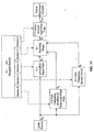
- FIG. 1 a block diagram of the preferred embodiment of the present invention, in which frequency response compensation is provided for one or more of a multiplicity of planar diaphragm speaker and enclosure combinations.
- the purpose of FIG. 1 is to compensate for the undesirable frequency response characteristics of an uncompensated planar diaphragm speaker mounted in an enclosure having a limited depth dimension, such as illustrated in FIG. 2.
- a typical planar diaphragm speaker mounted in an enclosure having a limited depth dimension has an unacceptably high system resonant frequency (F r ) and an unacceptably high system resonant Q (Q f ), resulting in a response peak in the range of 125 to 200 Hz. and essentially no response at all below approximately 50 Hz.
- the response peak for the speaker would be in the range of 25 to 50 Hz., and its low bass frequency response would extend well below 50 Hz.
- the uncompensated planar diaphragm speaker exhibits an integrated power response decline in a mid-treble region of approximately 5 kHz. and an integrated power response rise in a high-treble region above approximately 10 kHz. This, in turn, degrades the mid-range and treble reproduction accuracy of the speaker.
- the preferred embodiment of the frequency compensation system includes three stages.
- the first stage comprises an underdamped high-pass filter F-1.
- the second stage comprises a parallel configuration of an unmodified signal path P-1, a modified second-order, high-frequency high-pass filter F-2, and a mid-frequency gyrator circuit G-1.
- the third stage is a summing stage S-1.
- each daughter board carries some of the components of the foregoing stages or circuits that determine their specific frequency response characteristics.
- the frequency response of each individual stage or circuit and, therefore, their phase interactions and the overall frequency response or transfer function of the entire frequency compensation system can be adjusted or tailored for a specific planar diaphragm speaker/air chamber combination, as described in more detail below.
- the operation of the frequency compensation system of FIG. 1 is as follows.
- An input signal S IN from a suitable audio source such as a pre-amplifier or other line-level source of a sound system, is applied to the underdamped high-pass filter F-1 of the first stage.
- Stage F-1 applies a low-frequency boost response, as represented by response curve "a" in FIG. 3, to signal S IN , thereby producing output signal S 1 .
- boost is shown as approximately 15 dB at approximately 65 Hz.
- Signal S 1 from the underdamped high-pass filter F-1 is then simultaneously applied as an input signal to the unmodified signal path P-1, the modified second-order, high-frequency high-pass filter F-2, and the mid-frequency gyrator circuit G-1.
- the unmodified signal path stage P-1 applies one of an attenuated and non-attenuated path to signal S 1 , as represented by curve “d” in FIG. 3, thereby producing output signal S 2 .
- Curve “d” in FIG. 3 shows the frequency response when an attenuated path is applied to signal S 1 .
- the modified second-order, high-frequency high-pass filter stage F-2 applies a high-frequency, high-pass filter function and a gradual ultra-high-frequency roll-off to signal S 1 , as represented by curve "c" in FIG. 3, thereby producing output signal S 3 .
- a second-order cut-off below approximately 5 kHz. and a gradual roll-off above 5 kHz. is shown.
- the mid-frequency gyrator circuit stage G-1 applies a mid-frequency peak to signal S 1 , thereby producing output signal S 4 .
- signal S 4 is converted to a corresponding mid-frequency dip in signal S 1 , as represented by curve "b" in FIG. 3.
- the dip is shown as approximately 15 dB at about 200 Hz.
- Signals S 2 and S 3 are then applied in an additive manner to non-inverting inputs of summing stage S-1, and, as noted, signal S 4 is applied in a subtractive manner to the inverting input of the summing stage S-1.
- Signals S 2 , S 3 and S 4 thereby sum and phase interact with one another to produce a corrective transfer function, as represented in FIG. 4, which is provided as output signal Sour to a planar diaphragm loudspeaker or loudspeaker system.
- FIG. 6 is a schematic diagram of a circuit that is suitable for the underdamped high-pass filter F-1.
- An operational amplifier, or op-amp, IC1 processes an input signal to produce a filtered and peaked output signal, capacitors C1 and C2 and resistors R1 and R2 determine the filter cut-off frequency, and resistors R3 and R4 determine the amplitude of the peak.
- FIG. 7 A schematic diagram of a circuit that is suitable for the unmodified signal path P-1 is shown in FIG. 7. An input signal is processed by resistors R5 and R6 to provide an output signal equal to a sample of the input signal.
- FIG. 8 is a schematic diagram of a circuit that is suitable for the modified second-order, high-frequency high-pass filter F-2.
- An input signal is sequentially applied to a capacitor C3, a series resistor R7, a feedback resistor R8 and an input of an op-amp IC2.
- Op-amp IC2 thereby provides a first-order high-pass filtered signal that is sequentially applied to a capacitor C4, a series resistor R9, a feedback resistor R10 and an input of an op-amp IC3.
- Op-amp IC3 thereby provides as output a second-order high-pass filtered signal, in which the shape of the filter cut-off slope is determined by the cut-off frequency alignment of the two above-described cascaded filter stages.
- the output signal is further modified by a feedback capacitor C5, which operates with op-amp IC3 to provide a gradual decline in the output signal at very high frequencies.
- FIG. 9 A schematic diagram of a circuit that is suitable for the mid-frequency gyrator circuit G-1 is shown in FIG. 9.
- An input signal is sequentially applied to a resistor R11, a capacitor C6 and an input of an op-amp IC4.
- Op-amp IC4 provides an output signal that is simultaneously applied to a feedback resistor R13 and a series resistor R14.
- Resistor R14 and a resistor R15 provide an attenuated sample of the IC4 output signal to an input of an op-amp IC5.
- Op-amp IC5 provides an output signal that is simultaneously applied to a feedback capacitor C7 and to an input of op-amp IC4 through a series resistor R12.
- the output of op-amp IC4 is applied to voltage divider resistors R16 and R17, which provide an attenuated gyrator circuit output signal.
- Such gyrator circuit provides a resonant amplitude peak transfer function to the input signal, which peak is converted to an amplitude dip by means of inverted signal summing processes described below.
- the frequency of the dip is determined by resistor R12 and capacitors C6 and C7; the Q of the dip is determined by resistor R11; and the amplitude of the dip is determined by resistors R16 and R17.
- FIG. 10 is a schematic diagram of a circuit that is suitable for the summing stage S-1.
- An op-amp IC6 combines input signals IN 1 and IN 2 in an additive manner and input signal IN 3 in a subtractive manner, using a conventional arrangement of input and feedback resistors R18, R19, R20, R21 and R22, to produce an output signal equal to a phase-interactive combination of the input signals.
- one of a series of daughter boards D-1 ... D-n may interface with one or more the above-described stages or circuits that make up the frequency compensation system of FIG. 1.
- Each such daughter board may comprise a board or other unit on which one or more components from these stages or circuits are operably mounted. Any one of these daughter boards can then be plugged into or otherwise releasably connected to a main board on which the remaining components of the stages or circuits are contained.
- Each daughter board may comprise a standard parts carrier that plugs into a standard IC socket on the main board.
- each separate stage or circuit includes components for all five stages or circuits of the system (F-1, F-2, G-1, P-1 and S-1), there will be five corresponding sections A-E, respectively.
- Each section includes one or more passive components (e.g., resistors and/or capacitors) for each stage or circuit.
- section A for the underdamped high-pass filter F-1 may include some or all of capacitors C1 and C2 and resistors R1 and R2, which determine the filter cut-off frequency, and resistors R3 and R4, which determine the amplitude of the peak.
- section C for the mid-frequency gyrator circuit G-1 may include one or more of resistor R12 and capacitors C6 and C7, which determine the frequency of the dip; resistor R11, which determines the Q of the dip; and resistors R16 and R17, which determine the amplitude of the dip.
- Such components may optionally include at least one active component (e.g. , IC1-IC6) ordinarily mounted on the main board.
- each section A-E When daughter board D-1 is plugged into the main board, each section A-E separately interfaces with, and thereby determines the frequency response characteristics of, the stage or circuit to which it corresponds. The combined effects of the various sections of daughter board D-1, therefore, determines the overall frequency response characteristic or transfer function of the frequency compensation system.
- each of the other daughter boards D-2 . . . D-n contains its own unique combination of components to calibrate or adjust the frequency response characteristics of one or more stages or circuits. In this manner, a set of daughter boards D-1 ... D-n can be created to accommodate all of the combinations of planar diaphragm speakers and metal enclosures or boxes (or other air chambers) in a product line. By plugging in or otherwise connecting the appropriate daughter board to the main board, therefore, the system can be calibrated or adjusted to a specific planar diaphragm speaker/air chamber combination.
- a multi-section switch can be substituted for daughter boards D-1 ... D-n in FIG. 1 and utilized for selecting the different combinations of components for the various stages or circuits of the frequency compensation system.
- this approach would require that each frequency compensation system include all of the components from each of the daughter boards D-1 ... D-n, as well as a switch having both the same number of positions as the number of daughter boards and the same number of sections as the number of sections on each daughter board. Therefore, in general, the use of such a switch would not be as economical as the use of the daughter boards.
- FIG. 11 An alternative embodiment of a frequency compensation system of FIG. 1 is shown in FIG. 11.
- the alternative embodiment in FIG. 11 is similar to the system shown in FIG. 1, except that the underdamped high-pass filter stage F-1 is utilized to process the output signal rather than the input signal. Otherwise, the system of FIG. 11 is constructed and functions in a manner similar to the system of FIG. 1 and produces a similar result.
- input signal S IN is simultaneously applied as an input signal directly to the unmodified signal path P-1, the modified second-order, high-frequency high-pass filter F-2, and the mid-frequency gyrator circuit G-1.
- the unmodified signal path stage P-1 applies one of an attenuated and non-attenuated path to signal S IN , thereby producing output signal S 5 .
- the modified second-order, high-frequency high-pass filter stage F-2 applies a high-frequency, high-pass filter function and a gradual ultra-high-frequency roll-off to signal S IN , thereby producing output signal S 6 .
- the mid-frequency gyrator circuit stage G-1 applies a mid-frequency peak to signal S IN , thereby producing output signal S 7 , which, because it is applied to the inverting input of the summing stage S-1, is converted to a corresponding mid-frequency dip in signal S IN .
- Signals S 5 and S 6 are applied in an additive manner to non-inverting inputs of summing stage S-1, and signal S 7 is applied in a subtractive manner to the inverting input of the summing stage S-1.
- Summing stage S-1 produces output signal S 8 that is applied as an input signal to underdamped high-pass filter stage F-1, which provides a low-frequency boost response and produces output signal S OUT .
- the present invention provides for a simple and economical system that effectively compensates for the diminished sound reproduction capabilities of planar diaphragm loudspeakers mounted in air chambers having a limited depth dimension, and that can be readily and economically calibrated for a variety of specific planar diaphragm speaker/air chamber combinations. While particular forms of the invention have been illustrated and described, it will be apparent that this invention may be embodied and practiced in other specific forms, e.g., in analog or functionally equivalent digital implementation, without departing from the spirit and essential characteristics thereof.
Landscapes
- Physics & Mathematics (AREA)
- Engineering & Computer Science (AREA)
- Acoustics & Sound (AREA)
- Signal Processing (AREA)
- Circuit For Audible Band Transducer (AREA)
Applications Claiming Priority (2)
| Application Number | Priority Date | Filing Date | Title |
|---|---|---|---|
| US376652 | 1999-08-18 | ||
| US09/376,652 US6522758B1 (en) | 1999-08-18 | 1999-08-18 | Compensation system for planar loudspeakers |
Publications (1)
| Publication Number | Publication Date |
|---|---|
| EP1079663A2 true EP1079663A2 (fr) | 2001-02-28 |
Family
ID=23485903
Family Applications (1)
| Application Number | Title | Priority Date | Filing Date |
|---|---|---|---|
| EP00306965A Withdrawn EP1079663A2 (fr) | 1999-08-18 | 2000-08-15 | Système à compensation de fréquence pour écouteurs planars |
Country Status (2)
| Country | Link |
|---|---|
| US (1) | US6522758B1 (fr) |
| EP (1) | EP1079663A2 (fr) |
Cited By (1)
| Publication number | Priority date | Publication date | Assignee | Title |
|---|---|---|---|---|
| WO2004034735A1 (fr) * | 2002-10-11 | 2004-04-22 | Lopez Bosio Alejandro Jose Ped | Dispositif electroacoustique actif a egalisation monte sur des panneaux, procede de transformation desdits panneaux et de montage des dispositifs |
Families Citing this family (2)
| Publication number | Priority date | Publication date | Assignee | Title |
|---|---|---|---|---|
| US20040042625A1 (en) * | 2002-08-28 | 2004-03-04 | Brown C. Phillip | Equalization and load correction system and method for audio system |
| CN111479197B (zh) * | 2020-04-30 | 2021-10-01 | 北京猎户星空科技有限公司 | 一种音频播放方法、装置、系统、设备及介质 |
Family Cites Families (22)
| Publication number | Priority date | Publication date | Assignee | Title |
|---|---|---|---|---|
| US4053711A (en) | 1976-04-26 | 1977-10-11 | Audio Pulse, Inc. | Simulation of reverberation in audio signals |
| CA1175362A (fr) | 1980-03-12 | 1984-10-02 | Richard P. Robinson | Methode et appareil pour ameliorer l'image acoustique |
| US5412731A (en) | 1982-11-08 | 1995-05-02 | Desper Products, Inc. | Automatic stereophonic manipulation system and apparatus for image enhancement |
| US4569076A (en) * | 1983-05-09 | 1986-02-04 | Lucasfilm Ltd. | Motion picture theater loudspeaker system |
| JPS63224599A (ja) | 1987-03-13 | 1988-09-19 | Asa Plan:Kk | ステレオ処理装置 |
| US5185679A (en) * | 1988-05-12 | 1993-02-09 | Mitsubishi Denki Kabushiki Kaisha | Inversion phenomenon preventing circuit |
| US4933786A (en) | 1988-09-21 | 1990-06-12 | Maxtor Corporation | Fault tolerant index patterns and decoding means |
| US4997058A (en) * | 1989-10-02 | 1991-03-05 | Bertagni Jose J | Sound transducer |
| US5216718A (en) | 1990-04-26 | 1993-06-01 | Sanyo Electric Co., Ltd. | Method and apparatus for processing audio signals |
| JPH0435499A (ja) | 1990-05-31 | 1992-02-06 | Sony Corp | 音響付加回路 |
| JPH04176279A (ja) | 1990-11-09 | 1992-06-23 | Sony Corp | ステレオ/モノラル判別装置 |
| US5333201A (en) | 1992-11-12 | 1994-07-26 | Rocktron Corporation | Multi dimensional sound circuit |
| JP2897586B2 (ja) | 1993-03-05 | 1999-05-31 | ヤマハ株式会社 | 音場制御装置 |
| US5572591A (en) | 1993-03-09 | 1996-11-05 | Matsushita Electric Industrial Co., Ltd. | Sound field controller |
| US5400405A (en) | 1993-07-02 | 1995-03-21 | Harman Electronics, Inc. | Audio image enhancement system |
| JP3276528B2 (ja) | 1994-08-24 | 2002-04-22 | シャープ株式会社 | 音像拡大装置 |
| DE4435224A1 (de) | 1994-09-30 | 1996-04-04 | Nokia Deutschland Gmbh | Tonwiedergabeanordnung |
| JP2755208B2 (ja) | 1995-03-30 | 1998-05-20 | ヤマハ株式会社 | 音場制御装置 |
| US5638452A (en) | 1995-04-21 | 1997-06-10 | Rocktron Corporation | Expandable multi-dimensional sound circuit |
| US5872851A (en) | 1995-09-18 | 1999-02-16 | Harman Motive Incorporated | Dynamic stereophonic enchancement signal processing system |
| US5970153A (en) | 1997-05-16 | 1999-10-19 | Harman Motive, Inc. | Stereo spatial enhancement system |
| US6038323A (en) | 1997-11-17 | 2000-03-14 | Harman Motive Inc. | Stereophonic image enhancement system for use in automobiles |
-
1999
- 1999-08-18 US US09/376,652 patent/US6522758B1/en not_active Expired - Lifetime
-
2000
- 2000-08-15 EP EP00306965A patent/EP1079663A2/fr not_active Withdrawn
Cited By (1)
| Publication number | Priority date | Publication date | Assignee | Title |
|---|---|---|---|---|
| WO2004034735A1 (fr) * | 2002-10-11 | 2004-04-22 | Lopez Bosio Alejandro Jose Ped | Dispositif electroacoustique actif a egalisation monte sur des panneaux, procede de transformation desdits panneaux et de montage des dispositifs |
Also Published As
| Publication number | Publication date |
|---|---|
| US6522758B1 (en) | 2003-02-18 |
Similar Documents
| Publication | Publication Date | Title |
|---|---|---|
| CN104969570B (zh) | 具有并联分频器的相统一扬声器 | |
| JP3410206B2 (ja) | スピーカ装置 | |
| US8189822B2 (en) | Modular, line-array loudspeaker | |
| NZ508761A (en) | Capacitor-less crossover network for electro-acoustic loudspeakers | |
| US20040042625A1 (en) | Equalization and load correction system and method for audio system | |
| EP2104372B1 (fr) | Baffle étagé pour la synchronisation d'arrivée de signal acoustique | |
| US5384855A (en) | Audio system for vehicular application | |
| GB2163621A (en) | Loudspeaker system utilizing an equalizer circuit | |
| US7003124B1 (en) | System and method for adjusting frequency response characteristics of high-pass crossovers supplying signal to speakers used with subwoofers | |
| US6687379B1 (en) | System and method for adjusting the low-frequency response of a crossover that supplies signal to subwoofers in response to main-speaker low-frequency characteristics | |
| JPH09247784A (ja) | スピーカ装置 | |
| US2841648A (en) | Sound producing device | |
| US6522758B1 (en) | Compensation system for planar loudspeakers | |
| JPH02142285A (ja) | Hdtv‐テレビジヨン受信機用スピーカ装置 | |
| US7123724B1 (en) | Sound system | |
| EP0998168A1 (fr) | Système de compensation pour écouteurs planars | |
| JP4171023B2 (ja) | 映像受像機用スピーカシステム及びスピーカ設置方法 | |
| US12395780B2 (en) | Headphone using passive filter | |
| US6707919B2 (en) | Driver control circuit | |
| CN222283471U (zh) | 音频信号处理器和音响系统 | |
| CN1675959A (zh) | 扬声器设备 | |
| CN1458809A (zh) | 具有音调补偿的扩展立体声电路 | |
| RU2799663C1 (ru) | Фильтр для многополосной акустической системы | |
| JP4089592B2 (ja) | 電子鍵盤楽器用スピーカボックス | |
| JPH0625116Y2 (ja) | 車載用スピ−カシステム |
Legal Events
| Date | Code | Title | Description |
|---|---|---|---|
| PUAI | Public reference made under article 153(3) epc to a published international application that has entered the european phase |
Free format text: ORIGINAL CODE: 0009012 |
|
| AK | Designated contracting states |
Kind code of ref document: A2 Designated state(s): AT BE CH CY DE DK ES FI FR GB GR IE IT LI LU MC NL PT SE |
|
| AX | Request for extension of the european patent |
Free format text: AL;LT;LV;MK;RO;SI |
|
| STAA | Information on the status of an ep patent application or granted ep patent |
Free format text: STATUS: THE APPLICATION HAS BEEN WITHDRAWN |
|
| 18W | Application withdrawn |
Effective date: 20030730 |