EP1079923B1 - Flexibler behälter und rahmen für mikrowellen assistierte chemie - Google Patents
Flexibler behälter und rahmen für mikrowellen assistierte chemie Download PDFInfo
- Publication number
- EP1079923B1 EP1079923B1 EP99918741A EP99918741A EP1079923B1 EP 1079923 B1 EP1079923 B1 EP 1079923B1 EP 99918741 A EP99918741 A EP 99918741A EP 99918741 A EP99918741 A EP 99918741A EP 1079923 B1 EP1079923 B1 EP 1079923B1
- Authority
- EP
- European Patent Office
- Prior art keywords
- vessel
- lid
- frame
- microwave
- self venting
- Prior art date
- Legal status (The legal status is an assumption and is not a legal conclusion. Google has not performed a legal analysis and makes no representation as to the accuracy of the status listed.)
- Expired - Lifetime
Links
Images



Classifications
-
- H—ELECTRICITY
- H05—ELECTRIC TECHNIQUES NOT OTHERWISE PROVIDED FOR
- H05B—ELECTRIC HEATING; ELECTRIC LIGHT SOURCES NOT OTHERWISE PROVIDED FOR; CIRCUIT ARRANGEMENTS FOR ELECTRIC LIGHT SOURCES, IN GENERAL
- H05B6/00—Heating by electric, magnetic or electromagnetic fields
- H05B6/64—Heating using microwaves
- H05B6/80—Apparatus for specific applications
- H05B6/806—Apparatus for specific applications for laboratory use
-
- B—PERFORMING OPERATIONS; TRANSPORTING
- B01—PHYSICAL OR CHEMICAL PROCESSES OR APPARATUS IN GENERAL
- B01J—CHEMICAL OR PHYSICAL PROCESSES, e.g. CATALYSIS OR COLLOID CHEMISTRY; THEIR RELEVANT APPARATUS
- B01J19/00—Chemical, physical or physico-chemical processes in general; Their relevant apparatus
- B01J19/0053—Details of the reactor
- B01J19/0073—Sealings
-
- B—PERFORMING OPERATIONS; TRANSPORTING
- B01—PHYSICAL OR CHEMICAL PROCESSES OR APPARATUS IN GENERAL
- B01J—CHEMICAL OR PHYSICAL PROCESSES, e.g. CATALYSIS OR COLLOID CHEMISTRY; THEIR RELEVANT APPARATUS
- B01J19/00—Chemical, physical or physico-chemical processes in general; Their relevant apparatus
- B01J19/02—Apparatus characterised by being constructed of material selected for its chemically-resistant properties
-
- B—PERFORMING OPERATIONS; TRANSPORTING
- B01—PHYSICAL OR CHEMICAL PROCESSES OR APPARATUS IN GENERAL
- B01J—CHEMICAL OR PHYSICAL PROCESSES, e.g. CATALYSIS OR COLLOID CHEMISTRY; THEIR RELEVANT APPARATUS
- B01J19/00—Chemical, physical or physico-chemical processes in general; Their relevant apparatus
- B01J19/08—Processes employing the direct application of electric or wave energy, or particle radiation; Apparatus therefor
- B01J19/12—Processes employing the direct application of electric or wave energy, or particle radiation; Apparatus therefor employing electromagnetic waves
- B01J19/122—Incoherent waves
- B01J19/126—Microwaves
-
- G—PHYSICS
- G01—MEASURING; TESTING
- G01N—INVESTIGATING OR ANALYSING MATERIALS BY DETERMINING THEIR CHEMICAL OR PHYSICAL PROPERTIES
- G01N1/00—Sampling; Preparing specimens for investigation
- G01N1/28—Preparing specimens for investigation including physical details of (bio-)chemical methods covered elsewhere, e.g. G01N33/50, C12Q
- G01N1/44—Sample treatment involving radiation, e.g. heat
-
- H—ELECTRICITY
- H05—ELECTRIC TECHNIQUES NOT OTHERWISE PROVIDED FOR
- H05B—ELECTRIC HEATING; ELECTRIC LIGHT SOURCES NOT OTHERWISE PROVIDED FOR; CIRCUIT ARRANGEMENTS FOR ELECTRIC LIGHT SOURCES, IN GENERAL
- H05B6/00—Heating by electric, magnetic or electromagnetic fields
- H05B6/64—Heating using microwaves
- H05B6/6402—Aspects relating to the microwave cavity
-
- B—PERFORMING OPERATIONS; TRANSPORTING
- B01—PHYSICAL OR CHEMICAL PROCESSES OR APPARATUS IN GENERAL
- B01J—CHEMICAL OR PHYSICAL PROCESSES, e.g. CATALYSIS OR COLLOID CHEMISTRY; THEIR RELEVANT APPARATUS
- B01J2219/00—Chemical, physical or physico-chemical processes in general; Their relevant apparatus
- B01J2219/02—Apparatus characterised by their chemically-resistant properties
- B01J2219/0204—Apparatus characterised by their chemically-resistant properties comprising coatings on the surfaces in direct contact with the reactive components
- B01J2219/0218—Apparatus characterised by their chemically-resistant properties comprising coatings on the surfaces in direct contact with the reactive components of ceramic
-
- B—PERFORMING OPERATIONS; TRANSPORTING
- B01—PHYSICAL OR CHEMICAL PROCESSES OR APPARATUS IN GENERAL
- B01J—CHEMICAL OR PHYSICAL PROCESSES, e.g. CATALYSIS OR COLLOID CHEMISTRY; THEIR RELEVANT APPARATUS
- B01J2219/00—Chemical, physical or physico-chemical processes in general; Their relevant apparatus
- B01J2219/02—Apparatus characterised by their chemically-resistant properties
- B01J2219/025—Apparatus characterised by their chemically-resistant properties characterised by the construction materials of the reactor vessel proper
- B01J2219/0295—Synthetic organic materials
-
- B—PERFORMING OPERATIONS; TRANSPORTING
- B01—PHYSICAL OR CHEMICAL PROCESSES OR APPARATUS IN GENERAL
- B01J—CHEMICAL OR PHYSICAL PROCESSES, e.g. CATALYSIS OR COLLOID CHEMISTRY; THEIR RELEVANT APPARATUS
- B01J2219/00—Chemical, physical or physico-chemical processes in general; Their relevant apparatus
- B01J2219/08—Processes employing the direct application of electric or wave energy, or particle radiation; Apparatus therefor
- B01J2219/12—Processes employing electromagnetic waves
- B01J2219/1203—Incoherent waves
- B01J2219/1206—Microwaves
- B01J2219/1209—Features relating to the reactor or vessel
-
- B—PERFORMING OPERATIONS; TRANSPORTING
- B01—PHYSICAL OR CHEMICAL PROCESSES OR APPARATUS IN GENERAL
- B01J—CHEMICAL OR PHYSICAL PROCESSES, e.g. CATALYSIS OR COLLOID CHEMISTRY; THEIR RELEVANT APPARATUS
- B01J2219/00—Chemical, physical or physico-chemical processes in general; Their relevant apparatus
- B01J2219/08—Processes employing the direct application of electric or wave energy, or particle radiation; Apparatus therefor
- B01J2219/12—Processes employing electromagnetic waves
- B01J2219/1203—Incoherent waves
- B01J2219/1206—Microwaves
- B01J2219/1209—Features relating to the reactor or vessel
- B01J2219/1212—Arrangements of the reactor or the reactors
- B01J2219/1215—Single reactor
-
- B—PERFORMING OPERATIONS; TRANSPORTING
- B01—PHYSICAL OR CHEMICAL PROCESSES OR APPARATUS IN GENERAL
- B01J—CHEMICAL OR PHYSICAL PROCESSES, e.g. CATALYSIS OR COLLOID CHEMISTRY; THEIR RELEVANT APPARATUS
- B01J2219/00—Chemical, physical or physico-chemical processes in general; Their relevant apparatus
- B01J2219/08—Processes employing the direct application of electric or wave energy, or particle radiation; Apparatus therefor
- B01J2219/12—Processes employing electromagnetic waves
- B01J2219/1203—Incoherent waves
- B01J2219/1206—Microwaves
- B01J2219/1209—Features relating to the reactor or vessel
- B01J2219/1212—Arrangements of the reactor or the reactors
- B01J2219/1218—Multiple reactors
-
- B—PERFORMING OPERATIONS; TRANSPORTING
- B01—PHYSICAL OR CHEMICAL PROCESSES OR APPARATUS IN GENERAL
- B01J—CHEMICAL OR PHYSICAL PROCESSES, e.g. CATALYSIS OR COLLOID CHEMISTRY; THEIR RELEVANT APPARATUS
- B01J2219/00—Chemical, physical or physico-chemical processes in general; Their relevant apparatus
- B01J2219/08—Processes employing the direct application of electric or wave energy, or particle radiation; Apparatus therefor
- B01J2219/12—Processes employing electromagnetic waves
- B01J2219/1203—Incoherent waves
- B01J2219/1206—Microwaves
- B01J2219/1209—Features relating to the reactor or vessel
- B01J2219/1221—Features relating to the reactor or vessel the reactor per se
- B01J2219/1239—Means for feeding and evacuation
Definitions
- the present invention relates to microwave assisted chemistry techniques and apparatus, and in particular, relates to an apparatus that provides a safe and efficient release of pressure generated in closed vessels by chemical reactions that are microwave assisted.
- microwave assisted chemistry refers to the use of electromagnetic radiation within the microwave frequencies to provide the energy required to initiate, drive, or accelerate certain chemical reactions.
- heat energy is one of the most significant factors in increasing the rate of a wide variety of chemical reactions.
- generally familiar devices such as the Bunsen burner, other types of gas burners, hot plates, and other similar devices have historically been used to initiate or accelerate various chemical reactions.
- microwave assisted chemistry techniques are used to heat chemical reagents in the same way that a consumer microwave oven cooks food.
- microwave assisted chemistry techniques are used to heat chemical reagents in the same way that a consumer microwave oven cooks food.
- the ordinary consumer use of microwave energy with food and its laboratory use with chemical reagents are significant differences, however, between the ordinary consumer use of microwave energy with food and its laboratory use with chemical reagents.
- the devices and techniques required for microwave assisted chemistry are generally much more sophisticated than are the consumer-oriented devices and techniques.
- a laboratory microwave device and a consumer microwave offer the same advantage: in many circumstances they both greatly increase the rate at which materials can be heated as compared to the rates that they could be heated by ordinary conduction or convection heating.
- microwave assisted chemistry has been particularly valuable in driving or accelerating reactions that tend to be time-consuming under more conventional heating techniques.
- Particular examples include moisture analysis, in which samples must effectively be heated to dryness; digestion, a process in which a chemical composition is broken down into its elements for further analysis, with the breakdown generally being accomplished by heating the composition in one or more mineral acids; and the Kjeldahl techniques for nitrogen determination.
- moisture analysis, Kjeldahl, or digestion reactions can be very lengthy, extending for hours in some cases.
- microwave assisted chemistry is relatively new compared to some other techniques, it has become well established and accepted in a number of analytical applications.
- microwave is often used generically to refer to radiation with wavelengths of between about 1000 and 500,000 microns ( ⁇ ), and corresponding frequencies of between about 1 X 10 9 and 5 X 10 11 Hertz (Hz). These are arbitrary boundaries, however, and other sources refer to microwaves as having frequencies of between about 10 8 Hz and 10 12 Hz and wavelengths of between about 300 centimeters (cm) and 0.3 millimeters (mm). For commercial and consumer purposes in the United States, the available microwave frequencies are regulated by the Federal Communications Commission and are generally limited to certain frequencies such as 2450 megahertz (MHz).
- microwave assisted chemistry techniques are often carried out in closed vessels which are in turn placed inside a device that bears a superficial relation to a consumer microwave oven, but that is much more sophisticated in its source, waveguide, cavity, and control elements.
- the pressure release function destroys or consumes, even if intentionally, a part of the vessel system (e.g., a rupture disc).
- a part of the vessel system e.g., a rupture disc
- the invention meets this object with a self-venting sealable vessel system that comprises a vessel formed of a microwave transparent material, one end of which forms an opening for placing materials inside the vessel.
- a lid is seated against the opening, and a flexible frame surrounds and bears against the vessel and lid and is similarly formed of a microwave-transparent material.
- the vessel system further comprises a threaded opening in the flexible frame and an adjustable threaded bolt in the opening that bears directly against the vessel. This draws the flexible frame against the vessel and the vessel and lid against one another with a predetermined force based upon the extent to which the bolt is tightened to seal the vessel at low pressures at or below the predetermined force. This prevents the frame from flexing until the pressure inside the vessel exceeds the predetermined force, after which the frame flexes sufficiently to allow the lid to unseat and gases to vent safely from the vessel without rupturing the vessel or the frame.
- FIG. 1 is a perspective view of a vessel system according to the present invention and broadly designated at 10.
- the invention comprises a vessel 11 formed of a microwave transparent material, one end of which forms an opening 12 (Figure 2) for placing materials inside the vessel.
- a lid 13 is seated against the opening 12.
- a flexible frame 14 surrounds the vessel 11 and lid 13 and is similarly preferably formed of a microwave transparent material.
- Means shown as the bolt 15 urge the frame 14 against the vessel 11 and the seated lid 13 with a predetermined force to seal the vessel at low pressures and so that the frame 14 refrains from flexing until the pressure inside the vessel 11 exceeds the predetermined force, after which the frame 14 flexes sufficiently to allow the lid 13 to unseat from the vessel 11 and for gases to vent safely from the vessel 11 without rupturing the vessel 11 or the frame 14.
- the term "flexible” is, of course, relative. With respect to the present invention, the term refers to a frame that is dimensionally stable under normal conditions and not easily deformed. The frame will, however, flex without breaking under more severe forces; i.e., at bout 500 psi ( ⁇ 3.45 MPa) for certain materials and up to 1500 psi ( ⁇ 10.35 MPa) for other materials. Materials that will begin flexing at such pressures, particularly polymeric materials, are well understood in the art. Thus, the composition and structure of the frame can be selected without undue experimentation.
- the vessel 11 is cylindrical and the frame 14 is rectangular, although it will be understood that other shapes could be used without departing from the scope of the invention or the claims.
- the vessel 11 is formed of an inner liner 16 formed of a microwave transparent and chemically resistant material, and a pressure resistant reinforced outer sleeve 17 with one end of the inner liner 16 forming the mouth 12 for placing materials inside the vessel.
- the lid 13 is also formed of a microwave transparent chemically resistant material for being seated against the opening 12 and for closing the vessel 11.
- the inner liner 16 and the lid 13 are formed of materials that include tetrafluoroethylene polymers, glass, or quartz. It will be likewise understood that the term "chemically resistant” is necessarily relative, and that it refers herein to a material that resists attack from the chemical compositions that are expected to be placed therein, or to form as a reaction proceeds therein.
- the invention further preferably comprises a stiffening member 21 for being externally seated against the lid 13.
- Figure 2 illustrates a particularly preferred embodiment in which the stiffening member 21 is a circular disc that fits inside an identically sized circular recess in the lid 13.
- FIG. 2 further includes another seating member 20 which can be positioned at the opposite end of the vessel from the lid 13.
- Figure 2 illustrates that the seating member 20 can include a self-locating pin or nub 22 that fits into a corresponding opening 23 in the frame 14.
- the frame is formed of a material and with a size sufficient to give it a particularly desired strength so that it refrains from flexing until a sufficient pressure inside the vessel is reached.
- the frame along with the stiffening member and the seating member 20 are thus typically selected from the group consisting of high-strength thermoplastic polymers and engineering polymers.
- Typical polymers include, but are not limited to, ABS resins, acrylic resins, nylon, PEEK resins, phenolformaldehyde resins, polybutylene terephthalate, polycarbonate, higher strength polyethylene, polypropylene, and polystyrene, polyvinylchloride (PVC), and urea formaldehyde resins.
- Particularly preferred plastics are the polyether imide plastics such as ULTEM TM from General Electric.
- Thermoplastic materials can be made with varying strengths by a number of polymerization and catalyzation techniques that are well understood by those in the polymer arts and will not be otherwise repeated herein. In general, however, it will be understood that if the desired venting pressure is to be about 500 pounds per square inch (psi) ( ⁇ 3,45 MPa) the engineering plastic selected for the frame 14, and the frame's design, will be less rigid than that selected for the extremely high pressure vessels for which the frames need to remain rigid until pressures of about 1500 psi ( ⁇ 10.35 MPa) are reached.
- psi pounds per square inch
- FIGS. 1 and 2 illustrate that the means for urging the frame against the vessel, as well as the stiffening member and lid against the vessel, comprises a threaded opening 24 in the top portion of the frame 14 and the threaded bolt 15 that engages the opening 24.
- the bolt 15 is tightened in the opening 24, it urges the stiffening member 21 against the lid 13 and the lid 13 against the inner sleeve 16 and liner 17 and against the seating member 20 to preload the frame and vessel with the desired force.
- This force with which the vessel and frame are preloaded is either equal or proportional to the pressure at which it is thus-desired for the vessel to vent.
- the invention provides a simple yet elegant technique for self venting the vessel at particular desired pressures.
- the inner liner 16 can be formed of a polymer (e.g., PTFE), PFA (perfluoroalkoxy resins), glass, or quartz, as may be desired or necessary depending upon the reactions to be carried out therein.
- a polymer e.g., PTFE
- PFA perfluoroalkoxy resins
- glass e.g., glass, glass, or quartz
- the outer sleeve 17 is formed of a braided structure of fiberglass yarns such as is available from CEM Corporation of Matthews, North Carolina, the assignee of the present invention, in conjunction with their MARS 5 TM systems.
- the vessel can be reinforced in a manner set forth, for example, in commonly assigned U.S. Patents Nos. 5,427,741 and 5,520,886.
- the invention also offers advantages, however, for lower-pressure reactions in which pressure-driven safety venting is less of a concern.
- microwave-assisted techniques are useful in solvent extraction procedures. These tend to take place at lower pressures, but because organic extraction solvents tend to be both volatile and flammable, these techniques require that the vessels remain sealed against vapor release. Under these circumstances, the frame 14 and the bolt 15 provide the means for tightly sealing extraction reactions even at lower pressures. Stated differently, the vapor pressures generated during solvent extraction are generally insufficient to threaten the physical integrity of the vessel. Nevertheless, the escape of hot organic vapors could present an entirely different set of problems, and is preferably avoided.
- the invention is particularly useful when a group of vessels are used concurrently in a microwave cavity so that multiple reactions can be carried out at the same time.
- the invention further comprises a source of microwave radiation, a cavity in microwave communication with the source, and a plurality of the vessel systems 10 in the cavity.
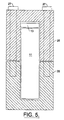
- Figures 5 and 6 illustrate other embodiments in which the frame comprises a plurality of portions that can be fastened together in a manner that urges the frame against the vessel and thus urges the lid and the vessel against each other.
- the vessel is again shown at 11 and the lid at 13, although in somewhat less detail than in the earlier drawings.
- the frame comprises two complementing U-shaped portions 25 and 26 which can be fastened together with the bolts 27. It will thus be seen that the combination of the frame portions 25 and 26 and the tightening bolts 27 urges the frame against the vessel 11 and the vessel and the lid 13 against each other in the same manner as does the frame 14 and bolt 15 illustrated in Figures 1-4.
- Figure 6 illustrates yet another embodiment in which the frame comprises a large U-shaped portion 30 and a capping portion 31, the two of which are urged against one another and against the vessel 11 and lid 13 by another set of bolts 32.
- the vessel 11 and lid 13 can be complemented by the sleeve and stiffening member arrangements illustrated in Figures 1-4. It will likewise be understood that other physical arrangements can be used to clamp or otherwise urge a frame against a vessel and its lid in a manner entirely consistent with the present invention and equivalent thereto.
Landscapes
- Chemical & Material Sciences (AREA)
- Physics & Mathematics (AREA)
- Electromagnetism (AREA)
- Health & Medical Sciences (AREA)
- Chemical Kinetics & Catalysis (AREA)
- Organic Chemistry (AREA)
- General Health & Medical Sciences (AREA)
- Analytical Chemistry (AREA)
- Immunology (AREA)
- Pathology (AREA)
- General Physics & Mathematics (AREA)
- Toxicology (AREA)
- Biochemistry (AREA)
- Life Sciences & Earth Sciences (AREA)
- Clinical Laboratory Science (AREA)
- Physical Or Chemical Processes And Apparatus (AREA)
- Constitution Of High-Frequency Heating (AREA)
- Closing Of Containers (AREA)
- Pressure Vessels And Lids Thereof (AREA)
Claims (16)
- Selbstentlüftendes, abdichtbares Behältersystem (10) für das einstellbare Freigeben von Druck während der mikrowellenunterstützten Chemie, das aufweist:ein Gefäß (11), das aus einem mikrowellendurchlässigen Material gebildet ist, wobei ein Ende des Gefäßes eine Öffnung (12) für das Plazieren von Materialien innerhalb des Gefäßes bildet,einen Deckel (13) für das Sitzen auf der Öffnung (12),einen flexibler Rahmen (14), der das Gefäß (11) und den Deckel (13) umgibt und gegen diese drückt und aus einem mikrowellendurchlässigen Material gebildet ist,eine Gewindeöffnung (24) in dem flexiblen Rahmen (14) undeinen einstellbaren Gewindebolzen (15) in der Gewindeöffnung, der direkt gegen das Gefäß (11) drückt und den flexiblen Rahmen (14) gegen das Gefäß, und das Gefäß und den Deckel (13) zueinander mit einer vorbestimmten Kraft zieht und so, daß der Rahmen (14) sich nicht biegt, bis der Druck innerhalb des Gefäßes die vorbestimmte Kraft überschreitet, wonach sich der Rahmen ausreichend verbiegt, um dem Deckel zu gestatten, den Sitz zu verlassen und Gase sicher aus dem Gefäß zu entlüften, ohne das Gefäß oder den Rahmen zu zerreißen.
- Selbstentlüftendes Gefäßsystem (10) nach Anspruch 1, das ein zylindrisches Gefäß (11) und einen rechteckigen Rahmen (14) aufweist.
- Selbstentlüftendes Gefäßsystem (10) nach Anspruch 1 oder Anspruch 2, in dem die Gewindeöffnung (24) in dem Abschnitt des flexiblen Rahmens (14) neben dem Deckel (13) ist und der Gewindebolzen (15) gegen den Deckel drückt.
- Selbstentlüftendes Gefäßsystem (10) nach Anspruch 1 oder Anspruch 2, bei dem die Gewindeöffnung (24) im Abschnitt des flexiblen Rahmens (14) gegenüber dem Deckel (13) ist und der Gewindebolzen (15) gegen den Boden des Gefäßes (11) drückt.
- Selbstentlüftendes Gefäßsystem (10) nach Anspruch 1, in dem der flexible Rahmen (14) eine Mehrzahl von Abschnitten aufweist, die in einer Art und Weise zusammengedrückt werden können, die den Rahmen (14) gegen das Gefäß (11) drückt und den Deckel (13) und das Gefäß aneinander drückt.
- Selbstentlüftendes System (10) nach Anspruch 1, das weiterhin aufweist:eine Mikrowellenstrahlquelle,eine Kavität in (Wellen-) Verbindung mit der Quelle undeine Mehrzahl der Gefäße (11) und der flexiblen Rahmen (14) in der Kavität.
- Selbstentlüftendes, abdichtbares Gefäßsystem nach Anspruch 1, in dem:das Gefäß eine innere Auskleidung (16), die aus einem mikrowellendurchlässigen, chemisch widerstandsfähigen Material gebildet ist und eine druckbeständige, verstärkte äußere Hülse (17) hat mit einem Ende der inneren Auskleidung (16), die eine Öffnung (12) bildet für das Plazieren von Materialien innerhalb des Gefäßes (11),wobei der Deckel (13) aus dem mikrowellendurchlässigen, chemisch resistenten Material gebildet ist und für das Aufsetzen auf der Öffnung (10) und für das Verschließen des Gefäßes (11) vorgesehen ist und
wobei das Gefäß (11) weiterhin ein Versteifungselement (21) aufweist, das von außen auf dem Deckel (13) sitzt. - Selbstentlüftendes Gefäßsystem (10) nach Anspruch 7, bei dem das mikrowellendurchlässige, chemisch resistente Material ein Tetrafluorethylenpolymer aufweist.
- Selbstentlüftendes Gefäßsystem (10) nach Anspruch 7, in dem die Auskleidung (16) aus Glas gebildet ist.
- Selbstentlüftendes Gefäßsystem (10) nach Anspruch 7, in dem die Auskleidung (16) aus Quarz gebildet ist.
- Selbstentlüftendes Gefäßsystem (10) nach Anspruch 7, bei dem der Deckel (13) aus einem technischen Kunststoff gebildet ist.
- Selbstentlüftendes Gefäßsystem (10) nach Anspruch 7, bei dem die äußere Hülse (17) geflochtene Fieberglasgarne aufweist.
- Selbstentlüftendes Gefäßsystem (10) nach Anspruch 7, bei dem der Rahmen (14) aus hochfesten, thermoplastischen Polymeren und technischen Polymeren ausgewählt ist.
- Selbstentlüftendes System (10) nach Anspruch 7, das weiterhin aufweist:eine Mikrowellenstrahlquelle,eine Kavität in Verbindung mit der Quelle undeine Mehrzahl der Gefäße (11) und der flexiblen Rahmen (14) in der Kavität.
- Selbstentlüftendes Gefäßsystem (10) nach Anspruch 7, bei dem die Auskleidung (16) aus Perfluoralkoxyharz gebildet ist.
- Selbstentlüftendes Gefäßsystem (10) nach Anspruch 7, bei dem die äußere Hülse (17) ein Polyetherimidharz aufweist.
Applications Claiming Priority (3)
| Application Number | Priority Date | Filing Date | Title |
|---|---|---|---|
| US6285898A | 1998-04-20 | 1998-04-20 | |
| US62858 | 1998-04-20 | ||
| PCT/US1999/008728 WO1999054034A1 (en) | 1998-04-20 | 1999-04-20 | Flexible vessel and frame for microwave assisted chemistry |
Publications (2)
| Publication Number | Publication Date |
|---|---|
| EP1079923A1 EP1079923A1 (de) | 2001-03-07 |
| EP1079923B1 true EP1079923B1 (de) | 2007-02-21 |
Family
ID=22045297
Family Applications (1)
| Application Number | Title | Priority Date | Filing Date |
|---|---|---|---|
| EP99918741A Expired - Lifetime EP1079923B1 (de) | 1998-04-20 | 1999-04-20 | Flexibler behälter und rahmen für mikrowellen assistierte chemie |
Country Status (8)
| Country | Link |
|---|---|
| US (1) | US6136276A (de) |
| EP (1) | EP1079923B1 (de) |
| JP (1) | JP4636686B2 (de) |
| AT (1) | ATE354437T1 (de) |
| AU (1) | AU3658699A (de) |
| CA (1) | CA2329518A1 (de) |
| DE (1) | DE69935217T2 (de) |
| WO (1) | WO1999054034A1 (de) |
Families Citing this family (12)
| Publication number | Priority date | Publication date | Assignee | Title |
|---|---|---|---|---|
| US6534140B2 (en) * | 1999-03-01 | 2003-03-18 | Cem Limited, L.L.C. | Pressure vessel with composite sleeve |
| US6287526B1 (en) * | 1999-06-01 | 2001-09-11 | Cem Corporation | Sealing closure for high pressure vessels in microwave assisted chemistry |
| DE10015794A1 (de) * | 2000-03-27 | 2001-10-11 | Univ Schiller Jena | Vorrichtung zur Durchführung chemischer Reaktionen und Prozesse in Hochfrequenzfeldern |
| JP4636664B2 (ja) * | 2000-10-11 | 2011-02-23 | 四国計測工業株式会社 | 化学反応促進用マイクロ波供給装置を設けた高温高圧容器 |
| US7285423B2 (en) | 2000-12-22 | 2007-10-23 | Biotage Ab | Penetrable pressure proof sealing for a container |
| US7144739B2 (en) * | 2002-11-26 | 2006-12-05 | Cem Corporation | Pressure measurement and relief for microwave-assisted chemical reactions |
| US20040179977A1 (en) | 2003-03-10 | 2004-09-16 | Cem Corporation | Controlled Pressure Release Vessel for Microwave Assisted Chemistry |
| US7307248B2 (en) * | 2003-12-09 | 2007-12-11 | Cem Corporation | Method and apparatus for microwave assisted high throughput high pressure chemical synthesis |
| US7829040B2 (en) * | 2009-03-05 | 2010-11-09 | Cem Corporation | High temperature high pressure vessel for microwave assisted chemistry |
| US10065168B2 (en) | 2016-05-02 | 2018-09-04 | Cem Corporation | High temperature pressure digestion vessel system with dual action seal |
| US10758880B2 (en) | 2016-05-04 | 2020-09-01 | Cem Corporation | Acid digestion instrument and vessel system |
| US11351515B2 (en) | 2019-03-14 | 2022-06-07 | Cem Corporation | Pressure-release vessel with rigid proportional liner and associated microwave-assisted chemistry methods |
Family Cites Families (14)
| Publication number | Priority date | Publication date | Assignee | Title |
|---|---|---|---|---|
| ATE19226T1 (de) * | 1980-08-04 | 1986-05-15 | Bon F Del | Selbstschliessendes ventil und verschlussvorrichtung. |
| EP0198675B2 (de) * | 1985-04-11 | 1994-04-13 | CEM Corporation | Selbstregulierendes Ventil in einem Mikrowellen- und Behältersystem |
| JPS63266271A (ja) * | 1987-04-18 | 1988-11-02 | Jgc Corp | 高圧容器 |
| US4882128A (en) * | 1987-07-31 | 1989-11-21 | Parr Instrument Company | Pressure and temperature reaction vessel, method, and apparatus |
| US5264185A (en) * | 1989-03-01 | 1993-11-23 | Floyd Terry S | High pressure and high temperature digestion vessel |
| US5230865A (en) * | 1989-09-08 | 1993-07-27 | Cem Corporation | Ventable rupture diaphragm-protected container for heating contained materials by microwave radiation |
| CA1337342C (en) * | 1989-09-08 | 1995-10-17 | Wyatt P. Hargett | Ventable rupture diaphragm-protected container for heating contained materials by microwave radiation |
| DE4018955A1 (de) * | 1990-06-13 | 1991-12-19 | Werner Lautenschlaeger | Probenbehaelter zum aufschliessen bzw. analysieren von probenmaterial |
| DE4108766C2 (de) * | 1991-03-18 | 1996-08-01 | Knapp Guenter Univ Prof Dipl I | Vorrichtung zum Erhitzen von Substanzen unter Entstehung hoher Drücke im Mikrowellenfeld |
| JPH05337353A (ja) * | 1992-06-03 | 1993-12-21 | Meiken Kagaku Kogyo Kk | 混合方法およびそれに用いる蓋止め構造 |
| US5427741A (en) * | 1993-05-19 | 1995-06-27 | Cem Corporation | Pressure resistant reinforcing means for containers for materials to be microwave heated |
| JP2808238B2 (ja) * | 1994-06-03 | 1998-10-08 | 蝶プラ工業株式会社 | 電子レンジでの加熱調理による殺菌状態のまま密閉できる通気栓付き密閉容器 |
| DE19639021A1 (de) * | 1996-09-23 | 1998-03-26 | Mikrowellen Systeme Mws Gmbh | Vorrichtung und Verfahren zum Behandeln einer chemischen Substanz durch Erhitzen unter Druck |
| US6086826A (en) * | 1997-09-15 | 2000-07-11 | Cem Corporation | Pressure sensing reaction vessel for microwave assisted chemistry |
-
1999
- 1999-04-20 EP EP99918741A patent/EP1079923B1/de not_active Expired - Lifetime
- 1999-04-20 JP JP2000544427A patent/JP4636686B2/ja not_active Expired - Lifetime
- 1999-04-20 AU AU36586/99A patent/AU3658699A/en not_active Abandoned
- 1999-04-20 CA CA002329518A patent/CA2329518A1/en not_active Abandoned
- 1999-04-20 WO PCT/US1999/008728 patent/WO1999054034A1/en not_active Ceased
- 1999-04-20 AT AT99918741T patent/ATE354437T1/de active
- 1999-04-20 DE DE69935217T patent/DE69935217T2/de not_active Expired - Lifetime
-
2000
- 2000-01-13 US US09/482,453 patent/US6136276A/en not_active Expired - Lifetime
Also Published As
| Publication number | Publication date |
|---|---|
| US6136276A (en) | 2000-10-24 |
| WO1999054034A1 (en) | 1999-10-28 |
| JP2002512112A (ja) | 2002-04-23 |
| EP1079923A1 (de) | 2001-03-07 |
| ATE354437T1 (de) | 2007-03-15 |
| JP4636686B2 (ja) | 2011-02-23 |
| AU3658699A (en) | 1999-11-08 |
| DE69935217D1 (de) | 2007-04-05 |
| CA2329518A1 (en) | 1999-10-28 |
| DE69935217T2 (de) | 2007-11-08 |
Similar Documents
| Publication | Publication Date | Title |
|---|---|---|
| US6136276A (en) | Flexible vessel and frame for microwave assisted chemistry | |
| CA1337342C (en) | Ventable rupture diaphragm-protected container for heating contained materials by microwave radiation | |
| JP5377625B2 (ja) | マイクロ波支援化学における高圧容器用の密封閉塞体 | |
| EP0198675B2 (de) | Selbstregulierendes Ventil in einem Mikrowellen- und Behältersystem | |
| US7820951B2 (en) | Microwave assisted chemical synthesis instrument with controlled pressure release | |
| EP1356710B1 (de) | Instrument für mikrowellenunterstützte chemische synthese versehen mit stationärer abstimmung | |
| US5520886A (en) | Explosion resistant reinforced container assemblies for materials to be microwave heated | |
| US4904450A (en) | High temperature and high pressure digestion vessel assembly | |
| EP1457255B1 (de) | Behälter mit geregelter Druckverminderung für mikrowellenunterstützte Chemie | |
| EP2230007B1 (de) | Hochtemperatur- und Hochdruckkessel für mikrowellengestützte Chemie | |
| EP1355735A1 (de) | Dämpfungsglied für die chemische synthese mit mikrowellen | |
| CA2303256C (en) | Pressure sensing reaction vessel for microwave assisted chemistry | |
| US20030170149A1 (en) | Pressure measurement in microwave-assisted chemical synthesis | |
| US11305285B2 (en) | Cap for closing a sample container for microwave treatment and a method and sample assembly for performing microwave treatment |
Legal Events
| Date | Code | Title | Description |
|---|---|---|---|
| PUAI | Public reference made under article 153(3) epc to a published international application that has entered the european phase |
Free format text: ORIGINAL CODE: 0009012 |
|
| 17P | Request for examination filed |
Effective date: 20001027 |
|
| AK | Designated contracting states |
Kind code of ref document: A1 Designated state(s): AT BE CH CY DE DK ES FI FR GB GR IE IT LI LU MC NL PT SE |
|
| RAP1 | Party data changed (applicant data changed or rights of an application transferred) |
Owner name: CEM CORPORATION |
|
| 17Q | First examination report despatched |
Effective date: 20030724 |
|
| GRAP | Despatch of communication of intention to grant a patent |
Free format text: ORIGINAL CODE: EPIDOSNIGR1 |
|
| GRAS | Grant fee paid |
Free format text: ORIGINAL CODE: EPIDOSNIGR3 |
|
| GRAA | (expected) grant |
Free format text: ORIGINAL CODE: 0009210 |
|
| AK | Designated contracting states |
Kind code of ref document: B1 Designated state(s): AT BE CH CY DE DK ES FI FR GB GR IE IT LI LU MC NL PT SE |
|
| PG25 | Lapsed in a contracting state [announced via postgrant information from national office to epo] |
Ref country code: NL Free format text: LAPSE BECAUSE OF FAILURE TO SUBMIT A TRANSLATION OF THE DESCRIPTION OR TO PAY THE FEE WITHIN THE PRESCRIBED TIME-LIMIT Effective date: 20070221 Ref country code: FI Free format text: LAPSE BECAUSE OF FAILURE TO SUBMIT A TRANSLATION OF THE DESCRIPTION OR TO PAY THE FEE WITHIN THE PRESCRIBED TIME-LIMIT Effective date: 20070221 Ref country code: DK Free format text: LAPSE BECAUSE OF FAILURE TO SUBMIT A TRANSLATION OF THE DESCRIPTION OR TO PAY THE FEE WITHIN THE PRESCRIBED TIME-LIMIT Effective date: 20070221 Ref country code: BE Free format text: LAPSE BECAUSE OF FAILURE TO SUBMIT A TRANSLATION OF THE DESCRIPTION OR TO PAY THE FEE WITHIN THE PRESCRIBED TIME-LIMIT Effective date: 20070221 |
|
| REG | Reference to a national code |
Ref country code: GB Ref legal event code: FG4D |
|
| REG | Reference to a national code |
Ref country code: CH Ref legal event code: EP |
|
| REF | Corresponds to: |
Ref document number: 69935217 Country of ref document: DE Date of ref document: 20070405 Kind code of ref document: P |
|
| REG | Reference to a national code |
Ref country code: IE Ref legal event code: FG4D |
|
| PG25 | Lapsed in a contracting state [announced via postgrant information from national office to epo] |
Ref country code: ES Free format text: LAPSE BECAUSE OF FAILURE TO SUBMIT A TRANSLATION OF THE DESCRIPTION OR TO PAY THE FEE WITHIN THE PRESCRIBED TIME-LIMIT Effective date: 20070601 |
|
| REG | Reference to a national code |
Ref country code: SE Ref legal event code: TRGR |
|
| PG25 | Lapsed in a contracting state [announced via postgrant information from national office to epo] |
Ref country code: PT Free format text: LAPSE BECAUSE OF FAILURE TO SUBMIT A TRANSLATION OF THE DESCRIPTION OR TO PAY THE FEE WITHIN THE PRESCRIBED TIME-LIMIT Effective date: 20070723 |
|
| REG | Reference to a national code |
Ref country code: CH Ref legal event code: NV Representative=s name: PATENTANWAELTE SCHAAD, BALASS, MENZL & PARTNER AG |
|
| NLV1 | Nl: lapsed or annulled due to failure to fulfill the requirements of art. 29p and 29m of the patents act | ||
| ET | Fr: translation filed | ||
| PLBE | No opposition filed within time limit |
Free format text: ORIGINAL CODE: 0009261 |
|
| STAA | Information on the status of an ep patent application or granted ep patent |
Free format text: STATUS: NO OPPOSITION FILED WITHIN TIME LIMIT |
|
| 26N | No opposition filed |
Effective date: 20071122 |
|
| PGFP | Annual fee paid to national office [announced via postgrant information from national office to epo] |
Ref country code: GR Payment date: 20070315 Year of fee payment: 9 |
|
| PG25 | Lapsed in a contracting state [announced via postgrant information from national office to epo] |
Ref country code: GR Free format text: LAPSE BECAUSE OF FAILURE TO SUBMIT A TRANSLATION OF THE DESCRIPTION OR TO PAY THE FEE WITHIN THE PRESCRIBED TIME-LIMIT Effective date: 20070522 |
|
| PG25 | Lapsed in a contracting state [announced via postgrant information from national office to epo] |
Ref country code: IE Free format text: LAPSE BECAUSE OF NON-PAYMENT OF DUE FEES Effective date: 20070420 |
|
| PG25 | Lapsed in a contracting state [announced via postgrant information from national office to epo] |
Ref country code: MC Free format text: LAPSE BECAUSE OF NON-PAYMENT OF DUE FEES Effective date: 20070430 |
|
| PG25 | Lapsed in a contracting state [announced via postgrant information from national office to epo] |
Ref country code: CY Free format text: LAPSE BECAUSE OF FAILURE TO SUBMIT A TRANSLATION OF THE DESCRIPTION OR TO PAY THE FEE WITHIN THE PRESCRIBED TIME-LIMIT Effective date: 20070221 |
|
| PG25 | Lapsed in a contracting state [announced via postgrant information from national office to epo] |
Ref country code: LU Free format text: LAPSE BECAUSE OF NON-PAYMENT OF DUE FEES Effective date: 20070420 |
|
| REG | Reference to a national code |
Ref country code: FR Ref legal event code: PLFP Year of fee payment: 17 |
|
| REG | Reference to a national code |
Ref country code: FR Ref legal event code: PLFP Year of fee payment: 18 |
|
| REG | Reference to a national code |
Ref country code: FR Ref legal event code: PLFP Year of fee payment: 19 |
|
| REG | Reference to a national code |
Ref country code: FR Ref legal event code: PLFP Year of fee payment: 20 |
|
| PGFP | Annual fee paid to national office [announced via postgrant information from national office to epo] |
Ref country code: GB Payment date: 20180329 Year of fee payment: 20 |
|
| PGFP | Annual fee paid to national office [announced via postgrant information from national office to epo] |
Ref country code: FR Payment date: 20180315 Year of fee payment: 20 |
|
| PGFP | Annual fee paid to national office [announced via postgrant information from national office to epo] |
Ref country code: CH Payment date: 20180416 Year of fee payment: 20 Ref country code: DE Payment date: 20180410 Year of fee payment: 20 |
|
| PGFP | Annual fee paid to national office [announced via postgrant information from national office to epo] |
Ref country code: AT Payment date: 20180326 Year of fee payment: 20 Ref country code: IT Payment date: 20180420 Year of fee payment: 20 |
|
| PGFP | Annual fee paid to national office [announced via postgrant information from national office to epo] |
Ref country code: SE Payment date: 20180411 Year of fee payment: 20 |
|
| REG | Reference to a national code |
Ref country code: DE Ref legal event code: R071 Ref document number: 69935217 Country of ref document: DE |
|
| REG | Reference to a national code |
Ref country code: CH Ref legal event code: PL |
|
| REG | Reference to a national code |
Ref country code: GB Ref legal event code: PE20 Expiry date: 20190419 |
|
| REG | Reference to a national code |
Ref country code: SE Ref legal event code: EUG |
|
| REG | Reference to a national code |
Ref country code: AT Ref legal event code: MK07 Ref document number: 354437 Country of ref document: AT Kind code of ref document: T Effective date: 20190420 |
|
| PG25 | Lapsed in a contracting state [announced via postgrant information from national office to epo] |
Ref country code: GB Free format text: LAPSE BECAUSE OF EXPIRATION OF PROTECTION Effective date: 20190419 |