EP1080653A2 - Struktur zur Längeneinstellung von Schmuckketten - Google Patents
Struktur zur Längeneinstellung von Schmuckketten Download PDFInfo
- Publication number
- EP1080653A2 EP1080653A2 EP99120458A EP99120458A EP1080653A2 EP 1080653 A2 EP1080653 A2 EP 1080653A2 EP 99120458 A EP99120458 A EP 99120458A EP 99120458 A EP99120458 A EP 99120458A EP 1080653 A2 EP1080653 A2 EP 1080653A2
- Authority
- EP
- European Patent Office
- Prior art keywords
- ornament
- resilient member
- chain
- length
- ornament chain
- Prior art date
- Legal status (The legal status is an assumption and is not a legal conclusion. Google has not performed a legal analysis and makes no representation as to the accuracy of the status listed.)
- Withdrawn
Links
Images




Classifications
-
- A—HUMAN NECESSITIES
- A44—HABERDASHERY; JEWELLERY
- A44C—PERSONAL ADORNMENTS, e.g. JEWELLERY; COINS
- A44C11/00—Watch chains; Ornamental chains
- A44C11/005—Watch chains; Ornamental chains with friction boxes adjustments
-
- A—HUMAN NECESSITIES
- A44—HABERDASHERY; JEWELLERY
- A44C—PERSONAL ADORNMENTS, e.g. JEWELLERY; COINS
- A44C5/00—Bracelets; Wrist-watch straps; Fastenings for bracelets or wrist-watch straps
- A44C5/18—Fasteners for straps, chains or the like
- A44C5/20—Fasteners for straps, chains or the like for open straps, chains or the like
- A44C5/209—Fasteners specially adapted for necklaces or bracelets made of pearls
Definitions
- the present invention relates to an improvement in a structure for adjusting the length of an ornament chain, in which the length of an ornament chain or a loop tie is adjusted with the use of an adjuster.
- This resilient member is formed in an arcuate leaf spring by bending opposite ends of a single leaf spring on the same side so as to have a semicylindrical shape so that the opposite ends have a back-to-back relationship, and a pair of left and right ornament chains are inserted and clamped between the back-to-back parts of the arcuate leaf spring.
- a main object of the present invention is to provide a structure for adjusting the length of an ornament chain, which can increase a clamping force without the ornament chain being damaged, by widening the clamping surface with respect to the ornament chain.
- Another object of the present invention is to provide a structure for similarly adjusting the lengths of even a pair of ornament chains.
- the structure for adjusting the length of an ornament chain has a single retainer 10 adapted to be fixed to an ornament.
- This retainer 10 is composed of a casing 1 and a cylindrical resilient member 4 incorporated in the casing 1.
- the casing 1 has a substantially cylindrical shape as shown in the figures, the casing 1 should not be limited to this shape, but it may have any shape such as a shape having a polygonal outer surface, an egg-like or Dharma-like shape whenever an ornament chain can be inserted thereinto.
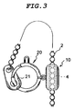
- the ornament chain 2 constitutes a necklace or a bracelet, and is a ball chain or a bean chain or any of other well-known chains.
- the casing 1 has a hole 3a on the side where the ornament chain 2 is inserted, and a hole 3b on the side where the ornament chain passing through the casing 1 is led out.
- the casing 1 is formed from a metal pipe which is cut into a predetermined length and opposite ends of which are rounded for chamfering, as shown in Fig. 1d.
- These holes 3a, 3b have a diameter which is set to be slightly larger than that of the outer periphery of the ornament chain so that the ornament chain can smoothly slide therein.
- the resilient member 4 is a cylindrical spring formed in such a way that a single metal leaf spring shown in Fig. 1a is cylindrically curved as shown in Fig. 1b, and a slit-like cutout 5 which is linearly extended is defined in the center joint part.
- the resilient member 4 has a diameter which is set to be small than that of the outer periphery of the ornament chain 2 so that an urging force is effected in a direction in which the outer periphery of the ornament chain 2 is fastened when the ornament chain 2 is inserted in this resilient member 4.
- Openings at opposite ends of the resilient member 4 define a hole 4a on the side where the ornament chain 2 is inserted, and a hole 4b on the side where the ornament chain 2 passing through the resilient member comes out.
- the resilient meter is a cylindrical shape by rounding a metal material, it is possible to prevent the resilient function from being lost due to heat.
- the resilient member 4 when the ornament chain 2 is inserted into the resilient member 4, the resilient member 4 is pushed out in its enlarging direction by the outer peripheral surface of the ornament chain 2 so that the resilient member 4 itself is urged in a decreasing direction.
- the ornament chain 2 inserted in the resilient member 4 is always fastened by the resilient member 4 due to fastening by the urging force of the resilient member 4.
- the resilient member 4 is accommodated in the hollow part of the retainer 1, and accordingly, the diameters of the insertion hole and the come-out hole of the retainer are set to be small so that the resilient member 4 is prevented from coming off.
- the ornament chain can be led out from the retainer so as to adjust the length thereof.
- the resilient member 4 is moved in the reverse direction within the retainer, and abuts against the inner wall of the hole on the opposite side, and accordingly, the ornament chain can be pulled out in the reverse direction while the resilient member is enlarged, similar to that mentioned above.
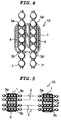
- This retainer 10 enables a plurality of ornament chains (two ornament chains in the embodiment shown in this figure) to be fitted in the casing 1 in parallel with each other, and resilient members 4 are fitted onto the ornament chains 2, respectively, within the casing 1.
- like reference numerals are use to denote like parts, but attached with "'" in order to distinguish the parts from one another, for the sake of brevity in explanation.
- a pair of holes 3a, 3a' and a pair of holes 3b, 3b' are formed in opposite ends of the casing 1, being opposed to one another.
- resilient members 4, 4' are arranged between the holes 3a, 3b, and between the holes 3a and 3a', respectively, and are fitted, respectively, on two ornament chains 2, 2' which are extend through the above-mentioned holes 3a, 3a' and 3b, 3b', in parallel with each other.
- These ornament chains 2, 2' may be used by winding a single ornament chain or by using a plurality of ornament chains in parallel with each other.
- the lengths of the ornament chains 2, 2' can be respectively adjusted by pulling the ornament chains 2, 2' themselves.
- Fig. 5 shows a retainer in which the lengths of a plurality of ornament chains (four ornament chains) can be adjusted.
- a retainer 10 shown in Fig. 6 is composed of a plurality of casings 1A, 1B which are disengageably coupled together, and resilient members 4 are incorporated in the casings 1A, 1B so that the ornament chains 2, 2' which are fitted in the casings 1A, 1B can slide therein so as to adjust their lengths.
- the casings 1A, 1B are provided therein with constituting parts of engaging means, locking structures or other removable coupling means, respectively, and accordingly, they can be disengageably coupled integrally with each other.
- a structure composed of a hook and a receiving part for receiving the former, a structure for concave and convex engagement, a structure using a magnetic attraction force of a magnet, and various kind of structures can be used.
- This retainer 10 may be used for a loop type necklace or the like.
- the casings 1A, 1B are separated from each other so as to remove the necklace, and with coupling the casings 1A, 1B together or without coupling them, the length of the ornament chain 2 can be adjusted by pulling the ornament chain 2.
- a resilient member 4 shown in Fig. 7 is formed with a raised part 7 on its peripheral wall, which is projected inward.
- this raised part 7 is formed in a substantially annular shape along the outer periphery, but it may be the one which is discretely projected, instead of the one which is continuously projected along the outer periphery as mentioned above.
- the ornament chain is, for example, a bean-like chain only composed of a ring-like chain which does not include spherical pieces or cubic pieces having a large contact area with respect to the resilient member, the raised part 7 abuts against the chain so as to surely effect an urging force.
- a resilient member 4' shown in Fig. 8 has a slit-like cutout 5' which is extended longitudinally while it is inclined with respect the axial direction of the resilient member 4', and accordingly, pieces of the ornament chain can hardly caught in the cut-out even though the pieces have angle corners.
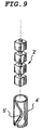
- a resilient member 4' shown in Fig. 9 has a slit-like cutout 5' which is axially extended, being wave-like curved.
- the shape of the cutout may be suitably changed in view of a shape of the ornament chains, that is, it may select any of various shapes, that is, the one obliquely inclined or meandering.
- one end part of the resilient member may be provided with a flange or may have a large thickness so as to prevent the resilient member from coming off even though a hole in the casing is enlarged.
- the resilient member is fitted on the ornament chain so as to be restrained, and accordingly, the clamping area of the resilient member for the ornament chain can be widened, thereby it is possible to enhance the camping force and as well to restrain the ornament chain from being damaged.
- the present invention is to provide a structure for adjusting the length of an ornament chain, in which the clamping area for the ornament chain is widened so as to apply a clamping force to the ornament chain without damaging the same.
- the structure is composed of a hollow casing formed therein with a pair of insertion or come-out openings for inserting the ornament chain, at separated positions, and a resilient member which is accommodated in the casing so as to be prevented from coming off, and which is adapted to be fitted on the ornament chain.
- the resilient member has a substantially cylindrical shape, defining a longitudinal slit-like cutout so that end part thereof are separated from each other in order to have resiliency, and the bore being set so that an urging force is effected in a direction in which the outer periphery of the ornament chain is fastened when the ornament chains is inserted in the resilient member.
Landscapes
- Adornments (AREA)
- Buckles (AREA)
Applications Claiming Priority (2)
| Application Number | Priority Date | Filing Date | Title |
|---|---|---|---|
| JP670999 | 1999-09-01 | ||
| JP670999 | 1999-09-01 |
Publications (2)
| Publication Number | Publication Date |
|---|---|
| EP1080653A2 true EP1080653A2 (de) | 2001-03-07 |
| EP1080653A3 EP1080653A3 (de) | 2001-10-17 |
Family
ID=11645834
Family Applications (1)
| Application Number | Title | Priority Date | Filing Date |
|---|---|---|---|
| EP99120458A Withdrawn EP1080653A3 (de) | 1999-09-01 | 1999-10-14 | Struktur zur Längeneinstellung von Schmuckketten |
Country Status (2)
| Country | Link |
|---|---|
| EP (1) | EP1080653A3 (de) |
| CN (1) | CN1286060A (de) |
Cited By (2)
| Publication number | Priority date | Publication date | Assignee | Title |
|---|---|---|---|---|
| WO2013023665A1 (en) * | 2011-08-16 | 2013-02-21 | Pandora A/S | Jewelry article |
| US8950214B2 (en) | 2013-02-11 | 2015-02-10 | Pandora A/S | Component with gripping element |
Families Citing this family (3)
| Publication number | Priority date | Publication date | Assignee | Title |
|---|---|---|---|---|
| DE602006000823T2 (de) * | 2006-03-24 | 2009-04-16 | The Swatch Group Management Services Ag | Längenverstellbares Armband |
| CN110122993B (zh) * | 2019-04-15 | 2021-05-14 | 丁朝朝 | 一种链状饰品用便于调节饰品长度的调节环 |
| CN110313690B (zh) * | 2019-07-10 | 2021-02-26 | 深圳市华乐珠宝首饰有限公司 | 一种空心珠与胶粒的组合成型工艺 |
Family Cites Families (5)
| Publication number | Priority date | Publication date | Assignee | Title |
|---|---|---|---|---|
| FR1175440A (fr) * | 1957-03-22 | 1959-03-26 | Fermoir pour bracelets, colliers ou autres anneaux souples d'ornement | |
| US4759398A (en) * | 1984-06-11 | 1988-07-26 | Renee William C | Operator for venetian blinds combination operator and venetian blind, and method of operating venetian blinds |
| DE9403789U1 (de) * | 1994-03-07 | 1994-05-19 | Wo & Wo Grün GmbH, Graz | Verbindungseinrichtung |
| DE19628783A1 (de) * | 1996-07-17 | 1998-01-29 | Helmut Deutzmann | Collier aus mehreren einzeln verwendbaren Halsketten |
| FR2780863B1 (fr) * | 1998-07-10 | 2000-09-15 | Cartier Int Bv | Dispositif de mise a longueur pour collier ou bracelet |
-
1999
- 1999-10-14 EP EP99120458A patent/EP1080653A3/de not_active Withdrawn
- 1999-11-05 CN CN 99123444 patent/CN1286060A/zh active Pending
Cited By (3)
| Publication number | Priority date | Publication date | Assignee | Title |
|---|---|---|---|---|
| WO2013023665A1 (en) * | 2011-08-16 | 2013-02-21 | Pandora A/S | Jewelry article |
| US8950214B2 (en) | 2013-02-11 | 2015-02-10 | Pandora A/S | Component with gripping element |
| US9839266B2 (en) | 2013-02-11 | 2017-12-12 | Pandora A/S | Component with gripping element |
Also Published As
| Publication number | Publication date |
|---|---|
| EP1080653A3 (de) | 2001-10-17 |
| CN1286060A (zh) | 2001-03-07 |
Similar Documents
| Publication | Publication Date | Title |
|---|---|---|
| CA1215849A (en) | Slip on connector for jewelry clasp and blank for forming the same | |
| US5036681A (en) | Magnetized ear piece | |
| US5099659A (en) | Magnetic jewelry clasp | |
| JP3631678B2 (ja) | 各々が一般に球状の形状を有する次々の要素で構成される装飾チェーン | |
| US4631929A (en) | Clutch in and for jewelry items | |
| US6418706B1 (en) | Watchband link assembly | |
| US20070000283A1 (en) | Structure for adjusting length of ornament chains | |
| GB2102525A (en) | Wall anchor assembly | |
| US6138333A (en) | Adjustable earring | |
| US12292070B2 (en) | Locking snap-in fasteners | |
| CN104082923B (zh) | 具有夹持元件的装饰部件 | |
| US7082651B2 (en) | Clasp for jewelry | |
| US3856422A (en) | Retention clip for ball and socket joint | |
| US5943923A (en) | Retaining device of socket spanner | |
| US5457860A (en) | Releasable clasp | |
| US5201197A (en) | Pierced earring mount locking member | |
| US5926996A (en) | Fishing line connector | |
| US5433088A (en) | Snap-on earring clasp | |
| US6298650B1 (en) | Easy adjustable snap link | |
| US6859982B1 (en) | Connector | |
| JP3934872B2 (ja) | 留め具および装身用チェーンのスライド構造 | |
| US20060021203A1 (en) | Attachable clamp for use with a brooch pin with a rotable clasp | |
| JP2001070018A (ja) | 装身用チェーンの長さ調節構造 | |
| JPS6310736Y2 (de) | ||
| JP3005130U (ja) | 鎖バンド |
Legal Events
| Date | Code | Title | Description |
|---|---|---|---|
| PUAI | Public reference made under article 153(3) epc to a published international application that has entered the european phase |
Free format text: ORIGINAL CODE: 0009012 |
|
| AK | Designated contracting states |
Kind code of ref document: A2 Designated state(s): AT BE CH CY DE DK ES FI FR GB GR IE IT LI LU MC NL PT SE Kind code of ref document: A2 Designated state(s): DE ES FR GB IT |
|
| AX | Request for extension of the european patent |
Free format text: AL;LT;LV;MK;RO;SI |
|
| PUAL | Search report despatched |
Free format text: ORIGINAL CODE: 0009013 |
|
| AK | Designated contracting states |
Kind code of ref document: A3 Designated state(s): AT BE CH CY DE DK ES FI FR GB GR IE IT LI LU MC NL PT SE |
|
| AX | Request for extension of the european patent |
Free format text: AL;LT;LV;MK;RO;SI |
|
| AKX | Designation fees paid |
Free format text: DE ES FR GB IT |
|
| STAA | Information on the status of an ep patent application or granted ep patent |
Free format text: STATUS: THE APPLICATION IS DEEMED TO BE WITHDRAWN |
|
| 18D | Application deemed to be withdrawn |
Effective date: 20020418 |