EP1080800A2 - Procédé pour le laminage flexible d'une bande métallique - Google Patents
Procédé pour le laminage flexible d'une bande métallique Download PDFInfo
- Publication number
- EP1080800A2 EP1080800A2 EP00116083A EP00116083A EP1080800A2 EP 1080800 A2 EP1080800 A2 EP 1080800A2 EP 00116083 A EP00116083 A EP 00116083A EP 00116083 A EP00116083 A EP 00116083A EP 1080800 A2 EP1080800 A2 EP 1080800A2
- Authority
- EP
- European Patent Office
- Prior art keywords
- metal strip
- rolling
- strip
- roll
- roll gap
- Prior art date
- Legal status (The legal status is an assumption and is not a legal conclusion. Google has not performed a legal analysis and makes no representation as to the accuracy of the status listed.)
- Granted
Links
Images

Classifications
-
- B—PERFORMING OPERATIONS; TRANSPORTING
- B21—MECHANICAL METAL-WORKING WITHOUT ESSENTIALLY REMOVING MATERIAL; PUNCHING METAL
- B21B—ROLLING OF METAL
- B21B37/00—Control devices or methods specially adapted for metal-rolling mills or the work produced thereby
- B21B37/16—Control of thickness, width, diameter or other transverse dimensions
- B21B37/24—Automatic variation of thickness according to a predetermined program
- B21B37/26—Automatic variation of thickness according to a predetermined program for obtaining one strip having successive lengths of different constant thickness
-
- B—PERFORMING OPERATIONS; TRANSPORTING
- B21—MECHANICAL METAL-WORKING WITHOUT ESSENTIALLY REMOVING MATERIAL; PUNCHING METAL
- B21B—ROLLING OF METAL
- B21B37/00—Control devices or methods specially adapted for metal-rolling mills or the work produced thereby
- B21B37/28—Control of flatness or profile during rolling of strip, sheets or plates
- B21B37/38—Control of flatness or profile during rolling of strip, sheets or plates using roll bending
-
- B—PERFORMING OPERATIONS; TRANSPORTING
- B21—MECHANICAL METAL-WORKING WITHOUT ESSENTIALLY REMOVING MATERIAL; PUNCHING METAL
- B21B—ROLLING OF METAL
- B21B37/00—Control devices or methods specially adapted for metal-rolling mills or the work produced thereby
- B21B37/70—Length control
-
- B—PERFORMING OPERATIONS; TRANSPORTING
- B21—MECHANICAL METAL-WORKING WITHOUT ESSENTIALLY REMOVING MATERIAL; PUNCHING METAL
- B21B—ROLLING OF METAL
- B21B15/00—Arrangements for performing additional metal-working operations specially combined with or arranged in, or specially adapted for use in connection with, metal-rolling mills
- B21B2015/0071—Levelling the rolled product
-
- B—PERFORMING OPERATIONS; TRANSPORTING
- B21—MECHANICAL METAL-WORKING WITHOUT ESSENTIALLY REMOVING MATERIAL; PUNCHING METAL
- B21B—ROLLING OF METAL
- B21B37/00—Control devices or methods specially adapted for metal-rolling mills or the work produced thereby
- B21B37/58—Roll-force control; Roll-gap control
-
- B—PERFORMING OPERATIONS; TRANSPORTING
- B21—MECHANICAL METAL-WORKING WITHOUT ESSENTIALLY REMOVING MATERIAL; PUNCHING METAL
- B21B—ROLLING OF METAL
- B21B38/00—Methods or devices for measuring, detecting or monitoring specially adapted for metal-rolling mills, e.g. position detection, inspection of the product
- B21B38/02—Methods or devices for measuring, detecting or monitoring specially adapted for metal-rolling mills, e.g. position detection, inspection of the product for measuring flatness or profile of strips
Definitions
- the invention relates to a method for flexible rolling of a metal strip, wherein the metal strip is guided through one between two during the rolling process Work rolls formed and adjustable roll gap that over the length of the metal strip Strip sections with different strip thickness can be achieved.
- the method of flexible rolling is usually based on coil winding Coil designed, but also variants such as coil on board or board on board known.
- the one applied over the reel helps Belt tensioning the rolling process and significantly improves the straightness of the finished Strip profile in the longitudinal direction, i.e. in the rolling direction. This also ensures flexible rolling from coil to coil at the same time high productivity because of the thickness profiles continuously generated in the band.
- Another possibility of correction consists in passing one roll of rolls through each Horizontal rotation around the center of its line of contact with the corresponding one Place the roller at an angle to its axis. Because of this inclination the gap at the ends of the roll bale changes while remaining unchanged in the middle remains.
- the inclination of the rollers allows the possibility of variation an approximate compensation of the deflection for almost all operating cases but with regard to the achievable accuracy of the aforementioned parabolic grinding To equate roll bales.
- both the strip thickness and the Flatness is constantly set, monitored via complex control loops and when it occurs Deviations are regulated by appropriate actuators.
- a regulatory process to regulate the roll deflection caused by rolling force in conventional Strip rolling process is known for example from DE 22 64 333 C3. Basically Such complex control loops can also be used in flexible rolling become. The problem, however, is that it regulates a certain response time and requires a certain period of time for the regulation to respond and the effect of a disturbance variable change through the effect of the regulation within the measuring and control accuracy is corrected.
- the present invention further relates to a method for flexible rolling a Metal strip, the metal strip being guided during the rolling process by a roll gap formed between two work rolls and thus adjustable, that over the length of the metal strip strip sections with different strip thickness can be achieved and wherein the metal strip is directed after the flexible rolling becomes.
- the rolling process can downstream straightening may be required to achieve the necessary for further processing To ensure straightness or flatness of the metal strip. This judging can be done, for example, by bending or stretch bending straightening.
- the metal strip is turned on and depending on the number of straightening rollers or straightening goods between the staggered straightening or bending rolls subjected to multiple back and forth processes with decreasing curvature.
- the upper straightening roller set is set so that the remaining residual stress is minimized in the leveling or rolling stock to be leveled.
- the first elastic-plastic bend must be larger than the largest curvature that existed in the initial state of the target. About one further decaying elastic-plastic bending back and forth can the curvature in To be dismantled more and more.
- the last elastic-plastic bending process must be designed so that the leveling material after the elastic springback is no longer curved.
- the object of the present invention is to provide a method as described in the introduction To provide flexible rolling of a metal strip in which no undesirable deviations in the length and / or thickness profile of the finished rolled and possibly straightened rolling stock.
- the previously derived and described task is the beginning of a method described type according to the invention essentially solved in that a Compensation of the temperature influence on the metal strip during the Rolling is carried out to deviations from the target thickness and / or target length of the individual strip sections at a predetermined end temperature of the metal strip avoid.
- the process according to the invention therefore firstly influences the temperature taken into account on the rolling stock during rolling, which leads to length and Deviations in thickness of the individual strip sections leads.
- the compensation takes place by knowing the change in length and thickness of the metal strip at different Temperatures that form the basis of the compensation.
- the Individual strip sections are therefore deliberately shorter than the specified target length of the straightened metal strip or thicker than the predetermined target thickness of the straightened Rolled metal strip, since after straightening the length of the individual strip sections increases and their thickness decreases.
- the invention thus sees a targeted Compensation or consideration of the directional influence already during the flexible Rolling process, so deviations of the directed profile from the target profile to avoid the metal band. So it will be the profile of the metal band during modified the rolling process so that the result of the later straightening process desired target profile is.
- the compensation of the straightening influence takes place during rolling taking into account the knowledge of the profile change of the rolling stock when straightening.
- the compensations described above can be controlled on the basis of a Model as well as regulating be carried out in the compensation of the temperature influence preferably based on the actual temperature of the metal strip or another parameter representing the temperature, such as e.g. B. Change in length a reference route, as well as a combination of these two options.
- the controlling intervention is always available immediately when a change in the roll gap is made because of a regulation do not respond immediately due to the required response and control time can, during the regulatory intervention immediately after changing the Roll gap should be made.
- a change is preferably used as control variables in the control or regulation of the roll gap and / or the rolling speed in question. Otherwise the Compensation during flexible rolling is preferably carried out in such a way that after the rolling process, the target geometry of the rolled metal strip at room temperature of about 20 ° C is reached.
- a process in which a size - in the present case the bending lines of the work rolls - of another size - in the present case the roll gap - is influenced in a predetermined, fixed context.
- the compensation of the bending line change due to the load changes in the case of a change in the roll gap is carried out by knowing the dependence of the bending line on the respective roll gaps. If, for example, the roll gap is adjusted from S 1 to S 2 for a specific rolling stock, this adjustment of the roll gap leads to a change in the deflection of the work rolls. This change in the bending line is known and forms the basis of the controlled compensation.
- the knowledge of the change in the bending line can follow from the given geometry, but can in particular be obtained empirically, namely by returning corresponding measurement variables during the rolling process.
- the bending line is adjusted directly as a function of the respective roll gaps by applying, ie increasing or decreasing, certain bending-back forces in order to obtain a uniform gap dimension over the length of the roll gap.
- the flatness follows to the controller and especially immediately after the setting of the Roll gap is controlled via at least one control loop. So it is intended that initially, d. H. when setting the roll gap, only a control is carried out. External disturbances with the exception of the changing roll gap or the rolling speed cannot be taken into account here. Is the controlling intervention However, when closed, the regulation addresses the remaining unpredictability in the volume to eliminate and thus achieve a flat metal strip. Accordingly can proceed when compensating for the influence of temperature and / or direction become.
- predetermined ones are determined depending on the different roll gaps Rebending forces on the work rolls and / or on intermediate rolls and / or applied to backup rolls to make a work roll bend or Intermediate and work roll bending or a support and work roll bending to achieve.
- the aforementioned control or control can preferably be implemented with the mentioned working and / or intermediate and / or back-up roll bending, since here - the travel speed of the roll gap accordingly - quick changes can be realized what is especially important for flexible rolling with sometimes very short strip sections.
- other options for influencing flatness would also be conceivable, e.g. B. by moving intermediate rolls on the six-high mill stand, by hydraulically supported rollers or through cross-rolling. But the goal is in everyone Fall, a flat, flexibly rolled strip with a given target geometry at the final temperature to manufacture and at the same time the reeling ability of such metal strips improve or optimize.
- the optical measurement of the flatness can be done directly behind the work rolls realize in a simple way.
- the flatness of the metal strip preferably over the entire width of the metal strip behind the roll gap for each Length increment measured.
- Laser thickness measurement across the entire width of the metal strip enables a simple way to optimize the bending line of the work rolls online.
- the laser thickness measurement via triangulation enables through the small measuring spot and the high measuring frequencies of 1 kHz and more even with short band sections about 50 mm long to determine the cross profile.
- a stressometer roll can be used.
- a roll stand 1 part of a roll stand 1 is on the one hand without counter-bending (Fig. 1) and on the other hand with counter-bending (Fig. 2).
- a cylindrical work roll 2 with roll balls 3 and journals 4, 5, the are stored in bearings 6, 7.
- a support roller is located above the work roll 2 8 with a cylindrical backup roll bale 9 and bearing pins 10, 11, which in Bearings 12, 13 are stored.
- the backup roll 8 is the upper rolls of the roll stand 1.
- the roll gap is located between the two work rolls S.
- Fig. 1 an application is shown in the rolling of a metal strip, not shown, in which a rolling force F W is exerted on the work roll 2.
- the rolling force F W causes an elastic deflection of the work roll 2, so that the bending line B of the work roll 2 results.
- the rolling force F W leads not only to a deflection of the work roll 2, but also to a deflection of the support roll 8, which is not shown in detail.
- the roll gap S has a constant, uniform gap dimension; an at least substantially constant constant distance between the two mutually facing surfaces of the work rolls is thus realized.
- the work roll 2 is not bent.
- the rolling force F W counteracted by the backing roll 8 applied bending forces F B.
- the bending line B runs that of the central axis corresponds to the work roll 2, parallel to the outside of the work roll 2 this is not the case with cambered roller bales. In this case one is over the Length of the work roll constant roll gap in contrast to the representation according to Fig. 2 bent the work roll, although the delimiting the roll gap Line or surface of the work roll runs horizontally.
- the flexible rolling of a metal strip is carried out so that the roll gap S is specifically changed during the rolling process by a predetermined change in thickness to achieve the metal strip over its length.
- predetermined rebending forces F B are applied to the support rolls 8 in order to achieve a work and support roll bending.
- rebending forces F B are applied to the work rolls 2 to compensate for the flatness.
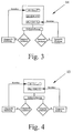
- a measured value acquisition is first carried out using appropriate measuring means. Both the longitudinal and the transverse profile are measured. The longitudinal profile or cross profile detection is then carried out, the control deviation between the actual value and the target value of the respective control variable being determined. The respective correction values are then fed to a control loop.
- longitudinal profile detection the change ⁇ h in the thickness of the metal strip is corrected to the predetermined target value in accordance with the predetermined target value. A corresponding change ⁇ S of the roll gap is required for this.
- the back bending forces F B to be applied to the respective work rolls 2 depend on the change in the roll gap S.
- the control circuit 15 shown in Fig. 4 are referred.
- the process for flexible rolling of a metal strip is such that the roll gap and / or specifically influences the rolling speed during the rolling process is the influence of temperature on rolling, which affects thickness and length of the metal strip has to compensate.
- first a profile recognition is carried out, with system deviations being determined.
- the roll gap control takes place depending on the measured longitudinal profiles and actual temperatures of the rolling stock.
- the method described above does not take account of the profile change of the metal strip when straightening the metal strip following the flexible Rollers.
- the method according to the invention for flexible rolling taking into account of the straightening influence is such that the roll gap and / or the rolling speed is specifically influenced during the rolling process, in order to Aligning profile changes to compensate during the rolling process.
- the roll gap and / or the feed speed of the rolling speed are changed in such a way via a control and / or regulating circuit that a shortened and thicker profile of the metal strip compared to the directed target profile results that corresponds to the specified target profile after straightening.
Landscapes
- Engineering & Computer Science (AREA)
- Mechanical Engineering (AREA)
- Control Of Metal Rolling (AREA)
- Metal Rolling (AREA)
Applications Claiming Priority (8)
| Application Number | Priority Date | Filing Date | Title |
|---|---|---|---|
| DE19936522 | 1999-08-06 | ||
| DE19936522 | 1999-08-06 | ||
| DE19951889 | 1999-10-28 | ||
| DE19951889 | 1999-10-28 | ||
| DE19954425 | 1999-11-11 | ||
| DE19954425 | 1999-11-11 | ||
| DE19962754 | 1999-12-23 | ||
| DE19962754A DE19962754A1 (de) | 1999-08-06 | 1999-12-23 | Verfahren zum flexiblen Walzen eines Metallbandes |
Publications (3)
| Publication Number | Publication Date |
|---|---|
| EP1080800A2 true EP1080800A2 (fr) | 2001-03-07 |
| EP1080800A3 EP1080800A3 (fr) | 2003-01-22 |
| EP1080800B1 EP1080800B1 (fr) | 2005-01-12 |
Family
ID=27438974
Family Applications (1)
| Application Number | Title | Priority Date | Filing Date |
|---|---|---|---|
| EP00116083A Expired - Lifetime EP1080800B1 (fr) | 1999-08-06 | 2000-07-27 | Procédé pour le laminage flexible d'une bande métallique |
Country Status (4)
| Country | Link |
|---|---|
| US (1) | US6336350B1 (fr) |
| EP (1) | EP1080800B1 (fr) |
| JP (1) | JP2001071013A (fr) |
| AT (1) | ATE286789T1 (fr) |
Cited By (3)
| Publication number | Priority date | Publication date | Assignee | Title |
|---|---|---|---|---|
| WO2008113426A3 (fr) * | 2007-03-22 | 2009-03-19 | Voestalpine Stahl Gmbh | Procédé de laminage flexible de bandes d'acier revêtues |
| EP3342494A1 (fr) * | 2016-12-30 | 2018-07-04 | Outokumpu Oyj | Appareil et procédé de laminage de bandes métalliques |
| CN114273463A (zh) * | 2020-09-27 | 2022-04-05 | 宝山钢铁股份有限公司 | 钢板自动多道次矫直方法 |
Families Citing this family (4)
| Publication number | Priority date | Publication date | Assignee | Title |
|---|---|---|---|---|
| DE19846900C2 (de) * | 1998-10-12 | 2000-08-10 | Thyssenkrupp Stahl Ag | Verfahren und Vorrichtung zum Herstellen eines Metallbandes für abzulängende Tailored Blanks |
| DE10246164B4 (de) * | 2002-10-02 | 2014-03-20 | Benteler Automobiltechnik Gmbh | Verfahren zum Herstellen von Strukturbauteilen |
| DE102005057742B3 (de) | 2005-12-02 | 2007-06-14 | Voestalpine Automotive Holding Gmbh | Verfahren und Vorrichtung zum Aufheizen von Stahlbauteilen |
| EP3168570A1 (fr) | 2015-11-10 | 2017-05-17 | Primetals Technologies France SAS | Méthode de mesure de planéité d'un produit métallique et dispositif associé |
Family Cites Families (24)
| Publication number | Priority date | Publication date | Assignee | Title |
|---|---|---|---|---|
| JPS5035900B2 (fr) * | 1972-03-28 | 1975-11-19 | ||
| DE2264333C3 (de) | 1973-12-17 | 1981-11-26 | Schloemann-Siemag Ag, 4000 Duesseldorf | Regelungsvorrichtung zum Ausregeln der walzkraftbedingten Walzendurchbiegung in einem Walzgerüst |
| DE2554246A1 (de) * | 1975-12-03 | 1977-06-16 | Achenbach Buschhuetten Gmbh | Verfahren und einrichtung zum regeln der planheit beim walzen von bandmaterial |
| JPS58135711A (ja) * | 1982-02-05 | 1983-08-12 | Toshiba Corp | 連続圧延機の制御方法およびその制御装置 |
| JPS6127111A (ja) * | 1984-07-16 | 1986-02-06 | Hitachi Ltd | 圧延材の形状制御方法 |
| JPS61172603A (ja) * | 1985-01-29 | 1986-08-04 | Sumitomo Metal Ind Ltd | 厚板圧延法 |
| JPS62158825A (ja) * | 1985-12-28 | 1987-07-14 | Nippon Steel Corp | 熱間圧延鋼板の冷却方法 |
| JPS62240105A (ja) * | 1986-04-11 | 1987-10-20 | Hitachi Cable Ltd | 高形状精度条の圧延方法 |
| JPS63119920A (ja) * | 1986-11-07 | 1988-05-24 | Kawasaki Steel Corp | 板圧延形状制御方法及び装置 |
| JPS63130205A (ja) * | 1986-11-19 | 1988-06-02 | Sumitomo Metal Ind Ltd | テ−パ金属板の板厚制御方法 |
| JPS63260604A (ja) * | 1987-04-20 | 1988-10-27 | Nippon Steel Corp | 薄鋼板の連続熱間圧延方法 |
| JPH03184612A (ja) * | 1989-12-12 | 1991-08-12 | Sumitomo Metal Ind Ltd | 板圧延における平坦度制御方法 |
| JPH04143608A (ja) * | 1990-10-05 | 1992-05-18 | Nkk Corp | 鋼板の平坦度測定装置 |
| DE4040360A1 (de) * | 1990-12-17 | 1991-06-27 | Siemens Ag | Regelung eines mehrgeruestigen warm- und/oder kaltband-walzwerks |
| JP2584922Y2 (ja) * | 1992-03-17 | 1998-11-11 | 石川島播磨重工業株式会社 | 形状検出装置 |
| FR2695049B1 (fr) * | 1992-09-03 | 1994-11-10 | Lorraine Laminage | Procédé et dispositif d'évaluation de la planéité d'une bande et ligne de fabrication d'une bande en continu comportant un dispositif d'évaluation de la planéité de la bande. |
| JPH06154806A (ja) * | 1992-11-20 | 1994-06-03 | Nkk Corp | 熱延ストリップの走間板厚変更圧延方法 |
| DE4309986A1 (de) | 1993-03-29 | 1994-10-06 | Schloemann Siemag Ag | Verfahren und Vorrichtung zum Walzen eines Walzbandes |
| JP2735145B2 (ja) * | 1993-10-28 | 1998-04-02 | 川崎製鉄株式会社 | 異形鋼板の圧延方法 |
| JP2861854B2 (ja) * | 1995-03-24 | 1999-02-24 | 住友金属工業株式会社 | テーパ厚鋼板の平坦矯正方法 |
| JP3045043B2 (ja) * | 1995-06-08 | 2000-05-22 | 住友金属工業株式会社 | テーパプレートの板厚制御方法 |
| EP0753359B1 (fr) * | 1995-07-10 | 2001-06-06 | Kawasaki Steel Corporation | Procédé et dispositif pour le laminage final en continu d'une bande en acier chaud |
| JP3116786B2 (ja) | 1995-10-31 | 2000-12-11 | 住友金属工業株式会社 | 熱延鋼帯の仕上圧延における仕上温度制御方法 |
| JP3186646B2 (ja) * | 1997-05-20 | 2001-07-11 | 住友金属工業株式会社 | テーパ鋼板の圧延方法 |
-
2000
- 2000-07-27 AT AT00116083T patent/ATE286789T1/de not_active IP Right Cessation
- 2000-07-27 EP EP00116083A patent/EP1080800B1/fr not_active Expired - Lifetime
- 2000-08-03 JP JP2000235782A patent/JP2001071013A/ja active Pending
- 2000-08-07 US US09/634,718 patent/US6336350B1/en not_active Expired - Fee Related
Cited By (12)
| Publication number | Priority date | Publication date | Assignee | Title |
|---|---|---|---|---|
| WO2008113426A3 (fr) * | 2007-03-22 | 2009-03-19 | Voestalpine Stahl Gmbh | Procédé de laminage flexible de bandes d'acier revêtues |
| US8522586B2 (en) | 2007-03-22 | 2013-09-03 | Voestalpine Stahl Gmbh | Method for flexibly rolling coated steel strips |
| EP3342494A1 (fr) * | 2016-12-30 | 2018-07-04 | Outokumpu Oyj | Appareil et procédé de laminage de bandes métalliques |
| WO2018122020A1 (fr) * | 2016-12-30 | 2018-07-05 | Outokumpu Oyj | Procédé et dispositif de laminage de bandes métalliques |
| CN110177627A (zh) * | 2016-12-30 | 2019-08-27 | 奥托库姆普联合股份公司 | 用于轧制金属条的方法及装置 |
| CN110177627B (zh) * | 2016-12-30 | 2021-08-06 | 奥托库姆普联合股份公司 | 用于轧制金属条的方法及装置 |
| TWI746756B (zh) * | 2016-12-30 | 2021-11-21 | 芬蘭商奧托昆布公司 | 用於軋延金屬條之方法與裝置 |
| RU2764727C2 (ru) * | 2016-12-30 | 2022-01-19 | Оутокумпу Оюй | Способ и устройство для прокатки металлических полос |
| AU2017387446B2 (en) * | 2016-12-30 | 2023-12-14 | Outokumpu Oyj | Method and device for rolling metal strips |
| US11865598B2 (en) | 2016-12-30 | 2024-01-09 | Outokumpu Oyj | Method for manufacturing flexible rolling of metal strips |
| CN114273463A (zh) * | 2020-09-27 | 2022-04-05 | 宝山钢铁股份有限公司 | 钢板自动多道次矫直方法 |
| CN114273463B (zh) * | 2020-09-27 | 2024-03-08 | 宝山钢铁股份有限公司 | 钢板自动多道次矫直方法 |
Also Published As
| Publication number | Publication date |
|---|---|
| ATE286789T1 (de) | 2005-01-15 |
| JP2001071013A (ja) | 2001-03-21 |
| EP1080800B1 (fr) | 2005-01-12 |
| EP1080800A3 (fr) | 2003-01-22 |
| US6336350B1 (en) | 2002-01-08 |
Similar Documents
| Publication | Publication Date | Title |
|---|---|---|
| EP1074317B1 (fr) | Procédé pour le laminage flexible d'une bande métallique | |
| EP1781429B1 (fr) | Procede pour dresser une bande metallique et dresseuse | |
| EP2477764B1 (fr) | Procédé et dispositif pour le dressage par traction et flexion continu de bandes métalliques | |
| EP0121148B1 (fr) | Procédé pour la fabrication de feuillard à chaud avec section et planéité de bande de haute qualité | |
| DE69404527T2 (de) | Walzwerk und Verfahren | |
| DE2543738A1 (de) | Verfahren und kalander zur herstellung von folien | |
| EP1955787B1 (fr) | Procédé et dispositif destinés à l'étirement de bandes de métal | |
| DE4136013C2 (de) | Verfahren und Vorrichtung zum Steuern eines Walzwerks | |
| DE2532710A1 (de) | Walzwerk zur herstellung nahtloser stahlrohre | |
| DE1427888B2 (de) | Einrichtung zur Dickenverringerung von Bandmaterial | |
| DE10037867A1 (de) | Verfahren zum flexiblen Walzen eines Metallbandes | |
| WO2022157312A1 (fr) | Utilisations de dispositifs de laminage à froid et procédé de laminage à froid contrôlé de feuille d'aluminium | |
| DE19962754A1 (de) | Verfahren zum flexiblen Walzen eines Metallbandes | |
| EP1080800B1 (fr) | Procédé pour le laminage flexible d'une bande métallique | |
| DE3240602C2 (fr) | ||
| EP3231522B1 (fr) | Controle robuste de tension de bande | |
| EP0734795B1 (fr) | Procédé pour la régulation à action directe d'épaisseur dans le laminage de feuillards | |
| DE4391396C2 (de) | Verfahren zum Walzen von H-Profilstahl | |
| EP3823771B1 (fr) | Procédé permettant de déterminer des grandeurs de réglage pour des éléments actifs de réglage du profil et de la planéité d'une cage de laminoir et des valeurs de profil et de planéité moyenne d'une bande métallique laminée à chaud | |
| DE3401894A1 (de) | Verfahren zum herstellen von walzband mit hoher bandprofil- und bandplanheitsguete | |
| DE69109945T2 (de) | Umkehrbares Walzverfahren. | |
| DE19939166B4 (de) | Verfahren zum flexiblen Walzen eines Metallbandes | |
| EP4178735B1 (fr) | Procédé et produit programme d'ordinateur pour calculer un programme de passes afin d'obtenir un procédé de laminage stable | |
| DE69612225T2 (de) | Verfahren und Vorrichtung zum Richten von flachen metallischen Produkten sowie Blechen, Metallbanden | |
| EP3097992A1 (fr) | Procédé de laminage échelonné d'une bande métallique |
Legal Events
| Date | Code | Title | Description |
|---|---|---|---|
| PUAI | Public reference made under article 153(3) epc to a published international application that has entered the european phase |
Free format text: ORIGINAL CODE: 0009012 |
|
| AK | Designated contracting states |
Kind code of ref document: A2 Designated state(s): AT BE CH CY DE DK ES FI FR GB GR IE IT LI LU MC NL PT SE |
|
| AX | Request for extension of the european patent |
Free format text: AL;LT;LV;MK;RO;SI |
|
| RIN1 | Information on inventor provided before grant (corrected) |
Inventor name: DR.-ING. ANDREAS HAUGER Inventor name: KLEIN, FRIEDRICH, DR.-ING. |
|
| PUAL | Search report despatched |
Free format text: ORIGINAL CODE: 0009013 |
|
| AK | Designated contracting states |
Kind code of ref document: A3 Designated state(s): AT BE CH CY DE DK ES FI FR GB GR IE IT LI LU MC NL PT SE |
|
| AX | Request for extension of the european patent |
Free format text: AL;LT;LV;MK;RO;SI |
|
| 17P | Request for examination filed |
Effective date: 20030314 |
|
| AKX | Designation fees paid |
Designated state(s): AT DE FR GB IT NL |
|
| 17Q | First examination report despatched |
Effective date: 20031107 |
|
| GRAP | Despatch of communication of intention to grant a patent |
Free format text: ORIGINAL CODE: EPIDOSNIGR1 |
|
| GRAS | Grant fee paid |
Free format text: ORIGINAL CODE: EPIDOSNIGR3 |
|
| GRAA | (expected) grant |
Free format text: ORIGINAL CODE: 0009210 |
|
| AK | Designated contracting states |
Kind code of ref document: B1 Designated state(s): AT DE FR GB IT NL |
|
| REG | Reference to a national code |
Ref country code: GB Ref legal event code: FG4D Free format text: NOT ENGLISH |
|
| REF | Corresponds to: |
Ref document number: 50009198 Country of ref document: DE Date of ref document: 20050217 Kind code of ref document: P |
|
| REG | Reference to a national code |
Ref country code: IE Ref legal event code: FG4D Free format text: GERMAN |
|
| GBT | Gb: translation of ep patent filed (gb section 77(6)(a)/1977) |
Effective date: 20050413 |
|
| PG25 | Lapsed in a contracting state [announced via postgrant information from national office to epo] |
Ref country code: IT Free format text: LAPSE BECAUSE OF NON-PAYMENT OF DUE FEES Effective date: 20050727 Ref country code: AT Free format text: LAPSE BECAUSE OF NON-PAYMENT OF DUE FEES Effective date: 20050727 |
|
| PLBE | No opposition filed within time limit |
Free format text: ORIGINAL CODE: 0009261 |
|
| STAA | Information on the status of an ep patent application or granted ep patent |
Free format text: STATUS: NO OPPOSITION FILED WITHIN TIME LIMIT |
|
| ET | Fr: translation filed | ||
| 26N | No opposition filed |
Effective date: 20051013 |
|
| PG25 | Lapsed in a contracting state [announced via postgrant information from national office to epo] |
Ref country code: NL Free format text: LAPSE BECAUSE OF NON-PAYMENT OF DUE FEES Effective date: 20060201 |
|
| GBPC | Gb: european patent ceased through non-payment of renewal fee |
Effective date: 20050727 |
|
| NLV4 | Nl: lapsed or anulled due to non-payment of the annual fee |
Effective date: 20060201 |
|
| PGFP | Annual fee paid to national office [announced via postgrant information from national office to epo] |
Ref country code: DE Payment date: 20070704 Year of fee payment: 8 |
|
| PG25 | Lapsed in a contracting state [announced via postgrant information from national office to epo] |
Ref country code: FR Free format text: LAPSE BECAUSE OF NON-PAYMENT OF DUE FEES Effective date: 20050731 |
|
| PG25 | Lapsed in a contracting state [announced via postgrant information from national office to epo] |
Ref country code: DE Free format text: LAPSE BECAUSE OF NON-PAYMENT OF DUE FEES Effective date: 20090203 |
|
| REG | Reference to a national code |
Ref country code: FR Ref legal event code: ST Effective date: 20111007 |