EP1080818A2 - Méthode et appareil de commande de l'amenée de fil d'un appareil de soudage TIG - Google Patents
Méthode et appareil de commande de l'amenée de fil d'un appareil de soudage TIG Download PDFInfo
- Publication number
- EP1080818A2 EP1080818A2 EP00116939A EP00116939A EP1080818A2 EP 1080818 A2 EP1080818 A2 EP 1080818A2 EP 00116939 A EP00116939 A EP 00116939A EP 00116939 A EP00116939 A EP 00116939A EP 1080818 A2 EP1080818 A2 EP 1080818A2
- Authority
- EP
- European Patent Office
- Prior art keywords
- movement
- wire
- welding wire
- welding
- wire feed
- Prior art date
- Legal status (The legal status is an assumption and is not a legal conclusion. Google has not performed a legal analysis and makes no representation as to the accuracy of the status listed.)
- Withdrawn
Links
Images
Classifications
-
- B—PERFORMING OPERATIONS; TRANSPORTING
- B23—MACHINE TOOLS; METAL-WORKING NOT OTHERWISE PROVIDED FOR
- B23K—SOLDERING OR UNSOLDERING; WELDING; CLADDING OR PLATING BY SOLDERING OR WELDING; CUTTING BY APPLYING HEAT LOCALLY, e.g. FLAME CUTTING; WORKING BY LASER BEAM
- B23K9/00—Arc welding or cutting
- B23K9/12—Automatic feeding or moving of electrodes or work for spot or seam welding or cutting
- B23K9/133—Means for feeding electrodes, e.g. drums, rolls, motors
- B23K9/1336—Driving means
Definitions
- the present invention relates to a method for controlling the wire feed movement of a welding wire for TIG manual welding and TIG automatic welding
- the TIG welding process is therefore preferred for welds where high Requirements for the weld seam quality (such as with X-ray seams, sealing seams or Root welds), as well as good appearance of the weld is required
- the quality of the weld seam is primarily based on the craftsmanship and the Experience of the TIG welder.
- weld seam consists of a series of individual drops of the molten welding wire.
- the quality of the weld results derive from the uniformity of the overlap of the drops, which in turn is immediate depends on the skill of the welder.
- the present invention sets itself the task by controlled automated feeding of the welding wire, even if the welder is less skilled, a higher weld quality to achieve and at the same time the time required for the production of the weld seam reduce significantly.
- the wire feed movement is a linear back-and-forth movement (Pendulum stroke movement), which is the characteristic of the material addition of the Hand welder is modeled.
- This type of movement is caused by that the jacking device (4-roll wire feed) for the automatic Welding wire feed is set in a linear back-and-forth movement (pendulum stroke) and a simultaneous feed movement of the wire takes place.
- the jacking device with integrated drive motor is mounted directly on one Lift carriage mounted.
- the lifting slide preferably consists of a high-performance plastic and is powered by a separate eccentric motor.
- the continuously driven one Welding wire also performs a pendulum stroke movement.
- both the frequency of the Pentelhub movement and the The driving speed can be adjusted independently of one another in defined areas.
- the frequency range of the pendulum stroke movement is between 100 and 1000 per minute.
- the Driving speed is in the range of 0.5 to 7 meters per minute.
- the welding wire is fed through the torch hose package up to approximately Middle of the handle, is then led out at the bottom of the handle and over brought a specially designed feeder to the welding position.
- a further increase in the quality of the weld seam is achieved in that the welding wire exits via a feed device, the outlet opening of the wire being none has central bore, but is slightly offset laterally and around the outlet opening Is bevelled 45 °.
- the emerging welding wire becomes an additional one Pendulum movement imposed by superimposing this pendulum movement on the Pendulum stroke motion of the jacking turns the tip of the welding wire into an elliptical Rotation offset and thus a rotational movement of the weld pool is achieved.
- the main features of this rotation of the weld pool are a broader, but flatter weld, better flank wettability, which causes binding errors be prevented, a higher welding speed, an improvement in Seam quality and a significant improvement in the visual appearance of the Weld seam, which has a fine-scaled appearance of continuous uniformity.
- the melting rate, d.i. the amount of welding wire introduced per unit of time increases by approximately 100 % increased, the welding in all welding positions - even overhead - essential can be carried out more easily.
- a further increase in the melting rate without a negative impact on the weld quality is achieved in that the welding wire in the feed by means of another Power source is preheated (hot wire process).
- the melting rate achievable in this way is about 150% compared to cold wire welding.
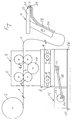
- the device according to the invention is shown in the figure. This is where the welding wire is 1 from the wire coil 2 via a wire feed device 3 continuously to a TIG welding torch 4 fed. This can be done by hand or on one Device be constructed.
- the wire feed device 3 consists of a housing 5 which is immobile is connected to a guide carriage 6, which preferably consists of a High-performance plastic is made.
- the guide carriage 6 is mounted on rollers 7, which along slot-shaped recesses 8 of the partially shown Guide carriage housing 9 are kept freely movable.
- a drive rod 10 engages on the guide carriage 6 via a holder 11 which is firmly connected to the guide carriage 6.
- the fixed on the gear motor 12 Eccentric disc 13 sets the drive rod 10 in an eccentrically rotating movement and this movement is transmitted to the carriage 6 through the bracket 11. Due to the bearing on the rollers 7, the guide carriage 6 executes a linear forward-backward movement parallel to the direction of advance of the welding wire.
- the point of attack 14 of the drive rod 10 on the eccentric disc 13 can be in one area from 0.5 to 10 millimeters, preferably in a range from 2 to 6 millimeters from The center of the pane can be staggered. This is a variable setting of the Pendulum stroke of the guide carriage 6 guaranteed.
- the gear motor 12 and that Guide carriage housing 9 are located on a common mounting plate 25, wherein a vibration damping plate 15 is arranged under the mounting plate 25.
- the wire feed device 3 has two pairs of feed rollers 16, 16a, which of a drive roller 17 are rotated, whereby the welding wire 1st is conveyed to the TIG welding torch 4 at a constant speed.
- the Drive roller 17 is of a not visible here, firmly on the Wire feeder-mounted drive motor driven.
- the TIG welding torch 4 consists of a handle 19 with one not here shown integrated actuation switch for controlling the wire feed and the On-off switch of the welding system.
- the wire feed line 20 leads through the handle 19, an inert gas supply line, not shown, and one, also not shown Cooling water line, as well as the power line for the burner body 22.
- the tungsten electrode 21 is integrated in the burner body 22.
- the wire feed line 20 has a bore 23 through which the welding wire 1 for Weld is performed.
- the outlet opening 24 is not exactly in the center of the Wire feed line 20, but is around 0.5 to 2 millimeters, preferably around 1.25 millimeters shifted from the center.
- the welding wire 1 leads immediately after it Exit 24 from the wire feed line 20 another, directed transversely to the exit direction Pendulum motion.
- this effect further reinforced by the outlet opening 24 against the axis of the feed line 20 by one Angle of 30 ° to 60 °, particularly preferably beveled by 45 °.
Landscapes
- Engineering & Computer Science (AREA)
- Physics & Mathematics (AREA)
- Plasma & Fusion (AREA)
- Mechanical Engineering (AREA)
- Arc Welding In General (AREA)
- Butt Welding And Welding Of Specific Article (AREA)
Applications Claiming Priority (2)
| Application Number | Priority Date | Filing Date | Title |
|---|---|---|---|
| AT59499U | 1999-09-01 | ||
| AT0059499U AT3863U1 (de) | 1999-09-02 | 1999-09-02 | Verfahren zur steuerung der drahtzufuhrbewegung für wig-schweissgeräte und vorrichtung zur durchführung des verfahrens |
Publications (2)
| Publication Number | Publication Date |
|---|---|
| EP1080818A2 true EP1080818A2 (fr) | 2001-03-07 |
| EP1080818A3 EP1080818A3 (fr) | 2003-07-23 |
Family
ID=3494724
Family Applications (1)
| Application Number | Title | Priority Date | Filing Date |
|---|---|---|---|
| EP00116939A Withdrawn EP1080818A3 (fr) | 1999-09-01 | 2000-08-07 | Méthode et appareil de commande de l'amenée de fil d'un appareil de soudage TIG |
Country Status (2)
| Country | Link |
|---|---|
| EP (1) | EP1080818A3 (fr) |
| AT (1) | AT3863U1 (fr) |
Cited By (14)
| Publication number | Priority date | Publication date | Assignee | Title |
|---|---|---|---|---|
| AT413955B (de) * | 2003-04-01 | 2006-07-15 | Plasch Siegfried Ing | Vorrichtung zum zuführen eines schweissdrahtes zu einer schweisseinrichtung |
| DE102008012615A1 (de) * | 2008-02-27 | 2009-09-03 | Lorch Schweißtechnik GmbH | Lichtbogenschweißgerät |
| US8367962B2 (en) | 2007-10-26 | 2013-02-05 | Ariel Andre Waitzman | Automated welding of moulds and stamping tools |
| WO2013056280A1 (fr) | 2011-10-21 | 2013-04-25 | Siegfried Plasch | Dispositif d'amenage d'un fil de soudage à un dispositif de soudage |
| EP2781291A1 (fr) | 2013-03-22 | 2014-09-24 | Siegfried Plasch | Dispositif permettant d'acheminer un fil de soudage jusqu'à un dispositif de soudage |
| DE102013105956A1 (de) | 2013-06-07 | 2014-12-24 | Schunk Lasertechnik GmbH | Vorrichtung zum Zuführen eines länglichen Gegenstandes |
| US9292016B2 (en) | 2007-10-26 | 2016-03-22 | Ariel Andre Waitzman | Automated welding of moulds and stamping tools |
| US9776274B2 (en) | 2007-10-26 | 2017-10-03 | Ariel Andre Waitzman | Automated welding of moulds and stamping tools |
| CN108188544A (zh) * | 2018-01-30 | 2018-06-22 | 苏州迈德焊接科技有限公司 | 一种低飞溅短路气保焊设备 |
| CN111215750A (zh) * | 2019-12-31 | 2020-06-02 | 广州汉马自动化控制设备有限公司 | 一种激光送丝焊机 |
| US10792682B2 (en) | 2017-10-02 | 2020-10-06 | Illinois Tool Works Inc. | Metal manufacturing systems and methods using mechanical oscillation |
| US10974337B2 (en) | 2015-08-17 | 2021-04-13 | Illinois Tool Works Inc. | Additive manufacturing systems and methods |
| CN113200408A (zh) * | 2021-05-17 | 2021-08-03 | 深圳市镒锦科技有限公司 | 一种自动焊接机的送丝装置 |
| CN115041781A (zh) * | 2022-05-20 | 2022-09-13 | 国家石油天然气管网集团有限公司 | 自动送丝装置及自动焊接系统 |
Families Citing this family (2)
| Publication number | Priority date | Publication date | Assignee | Title |
|---|---|---|---|---|
| DE102009031360A1 (de) * | 2009-07-02 | 2011-01-05 | Bayerische Motoren Werke Aktiengesellschaft | Drahtverbraucher mit einer Drahtfördereinrichtung |
| CN108098114B (zh) * | 2018-01-30 | 2024-10-29 | 吴钩科技(苏州)有限公司 | 一种氩弧焊脉冲送丝装置 |
Family Cites Families (4)
| Publication number | Priority date | Publication date | Assignee | Title |
|---|---|---|---|---|
| US4165829A (en) * | 1977-11-09 | 1979-08-28 | Fedorov Stanislav G | Method of feeding electrode wire and apparatus for performing same |
| EP0112422A1 (fr) * | 1982-12-22 | 1984-07-04 | Carl C. Heuckroth | Système d'avancement du fil |
| NL8301483A (nl) * | 1983-04-27 | 1984-11-16 | Philips Nv | Inrichting voor het axiaal verplaatsen van een draad. |
| US4873419A (en) * | 1985-03-01 | 1989-10-10 | Acheson Rees H | Automatic welding apparatus for weld build-up and method of achieving weld build-up |
-
1999
- 1999-09-02 AT AT0059499U patent/AT3863U1/de not_active IP Right Cessation
-
2000
- 2000-08-07 EP EP00116939A patent/EP1080818A3/fr not_active Withdrawn
Cited By (20)
| Publication number | Priority date | Publication date | Assignee | Title |
|---|---|---|---|---|
| AT413955B (de) * | 2003-04-01 | 2006-07-15 | Plasch Siegfried Ing | Vorrichtung zum zuführen eines schweissdrahtes zu einer schweisseinrichtung |
| US9292016B2 (en) | 2007-10-26 | 2016-03-22 | Ariel Andre Waitzman | Automated welding of moulds and stamping tools |
| US8367962B2 (en) | 2007-10-26 | 2013-02-05 | Ariel Andre Waitzman | Automated welding of moulds and stamping tools |
| US10279413B2 (en) | 2007-10-26 | 2019-05-07 | Ariel Andre Waitzman | Automated welding of moulds and stamping tools |
| US9776274B2 (en) | 2007-10-26 | 2017-10-03 | Ariel Andre Waitzman | Automated welding of moulds and stamping tools |
| US8857697B2 (en) | 2007-10-26 | 2014-10-14 | Ariel Andre Waitzman | Automated welding of moulds and stamping tools |
| DE102008012615A1 (de) * | 2008-02-27 | 2009-09-03 | Lorch Schweißtechnik GmbH | Lichtbogenschweißgerät |
| WO2013056280A1 (fr) | 2011-10-21 | 2013-04-25 | Siegfried Plasch | Dispositif d'amenage d'un fil de soudage à un dispositif de soudage |
| US9770778B2 (en) | 2013-03-22 | 2017-09-26 | Siegfried Plasch | Device for feeding a welding wire to a welding device |
| WO2014147245A1 (fr) | 2013-03-22 | 2014-09-25 | Siegfried Plasch | Dispositif d'amenée d'un fil de soudage à un dispositif de soudage |
| EP2781291A1 (fr) | 2013-03-22 | 2014-09-24 | Siegfried Plasch | Dispositif permettant d'acheminer un fil de soudage jusqu'à un dispositif de soudage |
| DE102013105956B4 (de) * | 2013-06-07 | 2016-08-18 | Schunk Lasertechnik GmbH | Vorrichtung zum Zuführen eines Schweissdrahtes |
| DE102013105956A1 (de) | 2013-06-07 | 2014-12-24 | Schunk Lasertechnik GmbH | Vorrichtung zum Zuführen eines länglichen Gegenstandes |
| US10974337B2 (en) | 2015-08-17 | 2021-04-13 | Illinois Tool Works Inc. | Additive manufacturing systems and methods |
| US10792682B2 (en) | 2017-10-02 | 2020-10-06 | Illinois Tool Works Inc. | Metal manufacturing systems and methods using mechanical oscillation |
| US12145223B2 (en) | 2017-10-02 | 2024-11-19 | Illinois Tool Works Inc. | Metal manufacturing systems and methods using mechanical oscillation |
| CN108188544A (zh) * | 2018-01-30 | 2018-06-22 | 苏州迈德焊接科技有限公司 | 一种低飞溅短路气保焊设备 |
| CN111215750A (zh) * | 2019-12-31 | 2020-06-02 | 广州汉马自动化控制设备有限公司 | 一种激光送丝焊机 |
| CN113200408A (zh) * | 2021-05-17 | 2021-08-03 | 深圳市镒锦科技有限公司 | 一种自动焊接机的送丝装置 |
| CN115041781A (zh) * | 2022-05-20 | 2022-09-13 | 国家石油天然气管网集团有限公司 | 自动送丝装置及自动焊接系统 |
Also Published As
| Publication number | Publication date |
|---|---|
| AT3863U1 (de) | 2000-09-25 |
| EP1080818A3 (fr) | 2003-07-23 |
Similar Documents
| Publication | Publication Date | Title |
|---|---|---|
| EP1080818A2 (fr) | Méthode et appareil de commande de l'amenée de fil d'un appareil de soudage TIG | |
| DE2324629C3 (de) | Schienengeführtes Lichtbogenschweißgerät | |
| DE2140545A1 (de) | Vorrichtung zum automatischen Lichtbogenschweißen durch programmierte Takte | |
| DE2723063A1 (de) | Vorrichtung zum automatischen bahnschweissen unter schutzgas nach dem tig- und/oder dem plasma-verfahren mit oder ohne verwendung von schweissmetall, zum stumpfschweissen von rohren, flanschen, fittings o.dgl. an rohre oder massivteile mit kreisquerschnitt | |
| EP2644306A1 (fr) | Dispositif de soudage et procédé de réglage d'un procédé de soudage | |
| DE19738785A1 (de) | Elektronische Schweißenergiequelle | |
| DE1440629B1 (de) | Schweissvorrichtung fuer rohrrundnaehte | |
| DE4207902A1 (de) | Automatische lichtbogen-schweissvorrichtung | |
| DE102009009180A1 (de) | Drahtvorschubvorrichtung | |
| DE1515167B2 (de) | Maschine zum automatischen elektrischen aufwaertsschweissen von senkrechten platten | |
| DE20013547U1 (de) | Vorrichtung zur Steuerung der Drahtzufuhr für WIG-Schweißgeräte | |
| DE1949903A1 (de) | Vorrichtung zum Verschweissen von Platten | |
| DE1615202A1 (de) | Vorrichtung und Verfahren zum Aufbringen einer Metallschicht | |
| DE102009009179A1 (de) | Vorrichtung zum Stellitieren von Sägezähnen und Verfahren | |
| EP1996365B1 (fr) | Procede et dispositif de soudage d'elements en materiaux metalliques | |
| DE202014011237U1 (de) | Vorrichtung zum Auftragsschweißen | |
| EP3674027A1 (fr) | Methode de controle d'un procede de soudage utilisant une electrode consommable, et appareil de soudage avec un tel controleur | |
| DE69815538T2 (de) | Verbesserte schweissbrenner und verwendungsverfahren | |
| DE1515160A1 (de) | Verfahren und Vorrichtung zum Schmelzschweissen | |
| AT347206B (de) | Verfahren zum mechanischen wig-schweissen mit zusatzmaterial | |
| DE102017126698B4 (de) | Verfahren und Vorrichtung zur additiven Fertigung | |
| AT238006B (de) | Verfahren und Vorrichtung zur Verbindung von verlegten Rohren miteinander durch Lichtbogenschweißung mit Hilfe einer sich verbrauchenden, schutzgasumgebenen Elektrode | |
| DE3304469C2 (de) | Verfahren und Vorrichtung zum Elektroschlackeschweißen | |
| DE3221897A1 (de) | Verfahren und vorrichtung zum aufbringen von stellitbezuegen durch schweissen auf die zaehne von band- oder kreissaegen | |
| DE3330545C2 (fr) |
Legal Events
| Date | Code | Title | Description |
|---|---|---|---|
| PUAI | Public reference made under article 153(3) epc to a published international application that has entered the european phase |
Free format text: ORIGINAL CODE: 0009012 |
|
| AK | Designated contracting states |
Kind code of ref document: A2 Designated state(s): AT BE CH CY DE DK ES FI FR GB GR IE IT LI LU MC NL PT SE |
|
| AX | Request for extension of the european patent |
Free format text: AL;LT;LV;MK;RO;SI |
|
| PUAL | Search report despatched |
Free format text: ORIGINAL CODE: 0009013 |
|
| AK | Designated contracting states |
Designated state(s): AT BE CH CY DE DK ES FI FR GB GR IE IT LI LU MC NL PT SE |
|
| AX | Request for extension of the european patent |
Extension state: AL LT LV MK RO SI |
|
| AKX | Designation fees paid | ||
| REG | Reference to a national code |
Ref country code: DE Ref legal event code: 8566 |
|
| STAA | Information on the status of an ep patent application or granted ep patent |
Free format text: STATUS: THE APPLICATION IS DEEMED TO BE WITHDRAWN |
|
| 18D | Application deemed to be withdrawn |
Effective date: 20040124 |