EP1080844B1 - Pince - Google Patents
Pince Download PDFInfo
- Publication number
- EP1080844B1 EP1080844B1 EP00116605A EP00116605A EP1080844B1 EP 1080844 B1 EP1080844 B1 EP 1080844B1 EP 00116605 A EP00116605 A EP 00116605A EP 00116605 A EP00116605 A EP 00116605A EP 1080844 B1 EP1080844 B1 EP 1080844B1
- Authority
- EP
- European Patent Office
- Prior art keywords
- pliers
- jaw
- plier
- forceps
- operating
- Prior art date
- Legal status (The legal status is an assumption and is not a legal conclusion. Google has not performed a legal analysis and makes no representation as to the accuracy of the status listed.)
- Expired - Lifetime
Links
- 238000006073 displacement reaction Methods 0.000 claims 3
- 230000014759 maintenance of location Effects 0.000 abstract 1
- 238000000418 atomic force spectrum Methods 0.000 description 15
- 239000000463 material Substances 0.000 description 4
- 125000006850 spacer group Chemical group 0.000 description 4
- 229910000831 Steel Inorganic materials 0.000 description 1
- 230000004308 accommodation Effects 0.000 description 1
- 238000005452 bending Methods 0.000 description 1
- 230000006835 compression Effects 0.000 description 1
- 238000007906 compression Methods 0.000 description 1
- 238000010276 construction Methods 0.000 description 1
- 238000002788 crimping Methods 0.000 description 1
- 230000002349 favourable effect Effects 0.000 description 1
- 210000003746 feather Anatomy 0.000 description 1
- 238000003754 machining Methods 0.000 description 1
- 238000004519 manufacturing process Methods 0.000 description 1
- 239000002184 metal Substances 0.000 description 1
- 238000000034 method Methods 0.000 description 1
- 230000002093 peripheral effect Effects 0.000 description 1
- 239000010959 steel Substances 0.000 description 1
Images


Classifications
-
- B—PERFORMING OPERATIONS; TRANSPORTING
- B25—HAND TOOLS; PORTABLE POWER-DRIVEN TOOLS; MANIPULATORS
- B25B—TOOLS OR BENCH DEVICES NOT OTHERWISE PROVIDED FOR, FOR FASTENING, CONNECTING, DISENGAGING OR HOLDING
- B25B7/00—Pliers; Other hand-held gripping tools with jaws on pivoted limbs; Details applicable generally to pivoted-limb hand tools
- B25B7/12—Pliers; Other hand-held gripping tools with jaws on pivoted limbs; Details applicable generally to pivoted-limb hand tools involving special transmission means between the handles and the jaws, e.g. toggle levers, gears
- B25B7/123—Pliers; Other hand-held gripping tools with jaws on pivoted limbs; Details applicable generally to pivoted-limb hand tools involving special transmission means between the handles and the jaws, e.g. toggle levers, gears with self-locking toggle levers
-
- B—PERFORMING OPERATIONS; TRANSPORTING
- B25—HAND TOOLS; PORTABLE POWER-DRIVEN TOOLS; MANIPULATORS
- B25B—TOOLS OR BENCH DEVICES NOT OTHERWISE PROVIDED FOR, FOR FASTENING, CONNECTING, DISENGAGING OR HOLDING
- B25B27/00—Hand tools, specially adapted for fitting together or separating parts or objects whether or not involving some deformation, not otherwise provided for
- B25B27/14—Hand tools, specially adapted for fitting together or separating parts or objects whether or not involving some deformation, not otherwise provided for for assembling objects other than by press fit or detaching same
- B25B27/146—Clip clamping hand tools
-
- B—PERFORMING OPERATIONS; TRANSPORTING
- B25—HAND TOOLS; PORTABLE POWER-DRIVEN TOOLS; MANIPULATORS
- B25B—TOOLS OR BENCH DEVICES NOT OTHERWISE PROVIDED FOR, FOR FASTENING, CONNECTING, DISENGAGING OR HOLDING
- B25B7/00—Pliers; Other hand-held gripping tools with jaws on pivoted limbs; Details applicable generally to pivoted-limb hand tools
- B25B7/12—Pliers; Other hand-held gripping tools with jaws on pivoted limbs; Details applicable generally to pivoted-limb hand tools involving special transmission means between the handles and the jaws, e.g. toggle levers, gears
-
- B—PERFORMING OPERATIONS; TRANSPORTING
- B25—HAND TOOLS; PORTABLE POWER-DRIVEN TOOLS; MANIPULATORS
- B25B—TOOLS OR BENCH DEVICES NOT OTHERWISE PROVIDED FOR, FOR FASTENING, CONNECTING, DISENGAGING OR HOLDING
- B25B7/00—Pliers; Other hand-held gripping tools with jaws on pivoted limbs; Details applicable generally to pivoted-limb hand tools
- B25B7/14—Locking means
Definitions
- the invention relates to a pair of pliers according to the preamble of patent claim 1.
- This known pliers includes a first working jaw and a fixed thereto first pliers handle, a pivotally mounted by means of a pivot axis on the first working jaws second working jaw, which forms a forceps jaw with the first working jaws, a second handle pivotally mounted on a pointing to the rear end of the clamp section the second working jaw is mounted, and a resilient connecting member, one end of which is attached to the second forceps handle just behind the second working jaw and the other end is attached to the first forceps handle.
- the connecting link serves to improve the elasticity of the pliers.
- the local figure 1 shows a toggle pliers, which has both a resilient toggle link connection and a sprung pivot axis.
- a toggle pliers is shown in the figures 11 and 12, in which a pivot axis is fixed to one of the working jaws and in the other working jaws a slot for receiving the pivot axis, the longitudinal direction in the forceps plane and at least approximately perpendicular to the forceps longitudinal direction, wherein a tension spring is fastened with one end to the pivot axis and with its other end to which the slot having working jaws.
- the invention has the object of developing a pair of pliers of the type mentioned so that can be achieved with her better work results.
- the solution of the problem is that the pivot axis is attached to one of the working jaws and in the other working jaws a slot for receiving the pivot axis is located, whose longitudinal direction in the forceps plane and at least approximately perpendicular to the forceps longitudinal direction, and that a tension spring is attached at one end to the pivot axis and with its other end to the slot having working jaws, wherein to produce a desired Force curve in the forceps jaw, the tension spring and the connecting member are formed so that over a limited by the length of the slot closing the working jaws the required mouth force is applied by the tension spring and the connecting member and is provided via an adjoining closing of the working jaws alone by the connecting member ,
- tension spring and resilient connecting member it is inventively possible to adjust the force curve in the forceps jaw in response to the closing movement of the working jaws very fine to desired conditions, even in the event that different sized objects are to be processed in the forceps jaw, so that from therefore achieve better work results. This is especially true when it is the pliers to a crimping tool with which, for example, wire end ferrules or other contact elements to be pressed onto cable ends.
- the force curve in the forceps jaw in response to the closing movement of the working jaws is adjusted by the fact that the respective spring characteristics of tension spring and link are combined.
- the tension spring otherwise used for the exact adjustment of the mouth force would be overstretched if the mouth jaws or the closing jaws of the working jaws are too large, the tension spring is switched off and the required jaw force is then applied only by the connecting link via a further closing path of the working jaws. As a result, the production can be over relatively large closing paths of the working jaws ensure a desired force curve in the forceps mouth.
- the spring characteristics of tension spring and connecting member can be adapted to each other so that when reaching the limited by the length of the slot closing path of the working jaws and further closing movement a jump-free force curve in the forceps jaw is achieved.
- the connecting member may be formed so that it gives way after exceeding a predetermined forceps jaw limit force.
- the pivot axis is preferably attached to the second working jaws, wherein the slot is located in the first working jaws.
- the tension spring can be fixed to the first and immovable working jaws, so that it is not pivoted during operation of the forceps and therefore does not distort their characteristic.
- the tension spring itself may have any suitable shape, but preferably also be formed, for example, as a V-shaped, U-shaped or ⁇ -shaped leaf spring.
- the desired characteristic can be adjusted in a particularly simple manner by selecting the appropriate dimensions or material thicknesses.
- a connecting member may preferably be a flat plate-like spring plate are used or a package of such feather plates, which can be easily predefined by appropriate material dimensions and material thicknesses in these sheets, the spring characteristic.
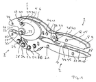
- a pair of pliers contains the following components: a first working jaw 1, a first gripper handle 2, a second working jaw 3, a second gripper handle 4, V-shaped spring plates 5 and 6 and a resilient connecting member 7, for example a compression spring.
- the first working jaws 1 and the first forceps handle 2 are integrally connected to each other and consist of a total of two mutually parallel sheets 8 and 9, which are held by a plurality of spacers 10, 11 and 12 at a distance from each other.
- the spacers 10, 11 and 12 each have a passage opening through which a bolt 13, 14 and 15 passes, which holds the sheets 8 and 9 together.
- the first working jaw 1 has a recess pointing in the direction of the second working jaw 3 for forming a forceps jaw 16 together with a corresponding recess in the second working jaw 3.
- the second forceps handle 4 is constructed in the same way as the first forceps handle 2. It also consists of two parallel plates 17 and 18, which are held by spacers 19 and 20 at a distance from each other. These spacers 19 and 20 are also hollow and receive bolts 21 and 22 which hold the sheets 17 and 18 together. In this case, the distance between the sheets 17 and 18 from one another corresponds to the spacing of the sheets 8 and 9.
- the plates 17 and 18 are extended in their plane. They take there a rear portion 23 of the second working jaw 3 between them.
- This rear portion 23 of the second working jaw 3 is pivotally mounted on the front portion of the second forceps handle 4 and arranged for this purpose rotatable about an axis 24 which is held by the sheets 17 and 18 and passes through an opening 46 in the rear portion 23.
- the second working jaw 3 As will be described in more detail with reference to Figure 2, belonging to the second working jaw 3 two lateral jaw plates 25 and 26, which laterally nestle against a central node element 27 of the second working jaw 3 and are held at a distance from each other, which is also the distance of Sheets 17, 18 and 8, 9 corresponds to each other. For cohesion of the jaw plates 25 and 26 with the central node element 27 are screws 28 and bolts 29, which enforce these elements.
- the second working jaw 3 is rotatably mounted on the first working jaw 1 via a pivot axis 30.
- pivot axis 30 On both outer and the second working jaws 3 outwardly projecting ends of the pivot axis 30 is seated one end of the V-shaped spring plates 5 and 6, the other end is attached in each case via a bolt 31 at the upper region of the upper working jaw 1, ie above the Pivot axis 30.
- the pivot axis 30 fits in a Recess 32 of the second working jaw 3 and on the other hand is in slots 33 which are located respectively in the sheets 8 and 9 of the first working jaw 1, wherein the longitudinal direction of the slots 33 is at least approximately perpendicular to the forceps longitudinal direction.
- the resilient connecting member 7 consists of two mutually parallel spring plates 34 and 35 and is articulated at its lower end in the front region of the second forceps handle 4, to which it is pivotable about an axis 36 which passes through the connecting member 7 and the sheets 17 and 18th is held.
- the axis 36 is shifted relative to the axis 24 to the rear end of the tong.
- the other end of the resilient connecting member 7 is pivotable on an eccentrically mounted shaft 37 and mounted on it on the first handle 2.
- the eccentrically mounted shaft 37 is displaced with respect to the axis 36 to the rear end of the pliers.
- axle stub 38 which are rotatably mounted in the sheets 8 and 9.
- FIG. 2 shows the more detailed construction of the pliers according to FIG. 1. The same elements are again provided with the same reference numerals and will not be described again.
- the central region of Figure 2 shows the more detailed structure of the lower working jaw 3.
- the central node element 27 consists in the present case of a middle plate 41, which consists for example of plastic, and two adjacent to both sides of the middle plate 41 outer plates 42nd and 43, which are made of steel. All plates 41, 42 and 43 form an approximately U-shaped component, the free legs facing the rear end of the pliers.
- the two jaw plates 25 and 26 are mounted laterally in the region of the base and the lower leg, wherein the sheets are held together by the screw 28.
- As an anti-rotation serve the bolts 29, which are held by retaining rings.
- the jaw plates 25 and 26 protrude from the bottom of the U-shaped component and together with the front portions of the sheets 8 and 9, the forceps jaw 16.
- both the jaw plates 25 and 26 and the sheets 8 and 9 bevelled so that their opposite edges to the rear tong end away from each other. From the clamping jaw plates 25, 26 and the sheets 8 and 9 carried machining elements in the forceps jaw 16 can therefore tilt according to the closed position of the pliers, namely about respective tilting axes which are passed through openings 44 and 45 of the working jaws 1 and 3 and the processing elements in Hold pliers mouth 16.
- the U-shaped component shown in the middle region of FIG. 2 has, in its remaining region of the base, the passage opening 32, which serves for the suitable accommodation of the pivot axis 30.
- This pivot axis 30 is, as already mentioned, taken up by the oblong holes 33, so that in this way the second working jaw 3 is pivotally mounted on the first working jaw 1.
- the free end of the lower leg of the U-shaped component in the central region of Figure 2 forms the said rear portion 23 of the second working jaw 3 and is provided there with a through-hole 46 through which the axis 24 passes to thus the second handle 4 to store the second working jaw 3 pivotally.
- the upper leg of the U-shaped component 27 in Figure 2 has on its inside a toothing 47 which is coaxial with the through hole 46.
- a pawl 48 In the toothing 47 engages a pawl 48, which can be seen in Figures 3 and 4.
- This pawl 48 may also be a pair of pawls, one of which engages in a toothing 47 on one of the plates 42, 43.
- the pawl 48 is pivotally mounted in the front region of the lower pliers handle 4 about an axis 49, which can be seen in the lower part of Figure 2.
- the axis 49 is movable on a path concentric with the axis 24.
- the length of the pawl 48 is greater than the distance between the axis 49 and teeth 47.
- Semicircular openings 50 coaxial with the axis 49 in the sheets 17 and 18 serve for manual actuation of the pawl 48 to bring it out of engagement with the teeth 47.
- In the front region of the second forceps handle 4 in Figure 2 are still through holes 51 and 52 can be seen in the sheets 17 and 18, which serve to receive the axes 24 and 36 in Figure 1.
- the pawl 48 can rotate about the axis 49 and held by a spring 57 which is fixed in the lower region of the connecting member 7 in a zero position, which is actually achieved only when the pawl 48 is disengaged from the toothing 47. If the pawl 48 engages with the toothing 47, it can give way, for example, when the forceps jaw 16 closes and not in the opposite direction. In order to bring the pawl 48 out of engagement with the teeth 47 in an intermediate position of the pliers handles 2, 4, connected to the pawl approach 58 can be manually operated through the slots 50 therethrough. The pawl 48 itself is practically in the interior of the central node element 27, so that no additional space inside the pliers is needed for this ratchet mechanism of teeth 47 and pawl 48. The pliers can therefore be reduced relatively compact.
- FIG. 3 shows the pliers in the fully opened state.
- both the total as a tension spring to be designated spring plates 5 and 6 are relieved and the connecting member. 7
- the force in the forceps jaw 16 is determined both by the spring plates 5 and 6 and by the connecting member 7.
- the characteristics of all springs add up and lead to a predetermined force curve in the forceps jaw 16 in response to the closing movement of the working jaws 1 and 3.
- the force curve in the forceps jaw is here essentially defined by the spring plates 5 and 6, with increasing closing movement of the forceps handles the pivot axis 30 is moved away in Figure 3 or from the first working jaw 1.
- the force curve in the forceps jaw can be generated by the V-shaped spring plates 5 and 6 for this short working path, with only a relatively small support by the connecting member 7 takes place.
- the working path then begins after the tool elements have come into contact with the object to be processed.
- These spring plates can be bent only over the length of the slot 33, since only in this case ensures that they actually deliver the desired force curve. A bending of the spring plates 5 and 6 beyond would lead to a distortion of the force curve, since then change their elastic properties in an undefined manner.
- FIG. 4 shows the pliers in the fully closed state.
- all the spring elements 5, 6, 7 still charged and the pawl 48 out of engagement with the teeth 47, so that the forceps can be opened again, if in the forceps jaw 16 is a machined (not shown) object.
- the connecting member 7 ensures due to its chosen spring characteristic that when a given forceps jaw limit force is exceeded due to the then incipient behavior of the connecting member 7, the forceps handles can still be closed, so that then the pliers can be opened again.
- FIG. 5 once again shows the forceps according to the invention in a perspective view, now supplemented with grip shells 59 and 60 arranged on the metal sheets 8, 9 and 17, 18.
- the inventive pliers can be present as a single tool or as an integral part of a machine tool.
- the forceps handles 2, 4 may be formed so that the forceps can be connected via their forceps handles with a machine for forceps drive.
- the pliers but also in whole or in parts may be a permanent part of a machine tool for driving the pliers.
- At least the forceps handles of the forceps can be parts of this machine tool.
- the pliers handles could be coupled to the rest of the pliers parts, which could be the pliers handles combine with each other different pliers parts of the type described above. One could thus take into account different dimensions of the material to be processed.
- FIG. 4 for example, a machine M connected to the forceps handles 2, 4 is shown with dashed lines.
- the machine M is practically simulated the movement of the pliers handles 2, 4 for driving the pliers.
Landscapes
- Engineering & Computer Science (AREA)
- Mechanical Engineering (AREA)
- Gripping Jigs, Holding Jigs, And Positioning Jigs (AREA)
- Surgical Instruments (AREA)
- Scissors And Nippers (AREA)
- Manipulator (AREA)
- Crystals, And After-Treatments Of Crystals (AREA)
Claims (9)
- Pince, comprenant une première mâchoire de travail (1) et une première poignée de pince (2) reliée rigidement à celle-ci; une deuxième mâchoire de travail (3), montée à pivotement au moyen d'un axe de pivotement (30) et formant avec la première mâchoire de travail (1) une gueule de pince; une deuxième poignée de pince (4), montée à pivotement sur un tronçon (23), tourné vers l'extrémité arrière de pince, de la deuxième mâchoire de travail (3); et un organe de liaison (7) élastique, dont une extrémité est montée sur la deuxième poignée de pince (4), à faible distance derrière la deuxième mâchoire de travail (3), et dont l'autre extrémité est montée sur la première poignée de pince (2); caractérisée en ce que- l'axe de pivotement (30) est fixé sur l'une des mâchoires de travail (3) et, dans l'autre mâchoire de travail (1), se trouve un trou oblong (33), pour recevoir l'axe de pivotement (30), dont la direction longitudinale s'étend dans le plan de pince et au moins à peu près perpendiculairement à la direction longitudinale de la pince;- un ressort de traction (5, 6) est fixé, par une première extrémité, sur l'axe de pivotement (30) et, par son autre extrémité, sur la mâchoire de travail (1) présentant le trou oblong (33),et en ce que- pour produire une allure souhaitée de la courbe de la force à la gueule de pince (16), le ressort de traction (5, 6) et l'organe de liaison (7) sont réalisés de manière que, sur la valeur d'une course de fermeture, limitée par la longueur du trou oblong (33), des mâchoires de travail (1, 3) la force à la gueule nécessaire, est appliquée par le ressort de traction (5, 6) et par l'organe de liaison (7) et, sur une course de fermeture s'y rapportant des mâchoires de travail (1, 3), est fournie seulement par l'organe de liaison (7).
- Pince selon la revendication 1, caractérisée en ce que les caractéristiques élastiques du ressort de traction (5, 6) et de l'organe de liaison (7) sont adaptées les unes aux autres, de manière que, à l'atteinte de la course de fermeture, limitée par la longueur du trou oblong (33), des mâchoires de travail (1, 3) et en poursuivant le déplacement de fermeture, on obtienne dans la gueule de pince (16)une évolution de la force la plus possible exempte de sursaut.
- Pince selon la revendication 1 ou 2, caractérisée en en ce que l'organe de liaison (7) est réalisé de manière que, après avoir dépassé une force limite prédéterminée à la gueule de pince, il se relâche fortement.
- Pince selon l'une des revendications 1 à 3, caractérisée en ce que l'axe de pivotement (30) est fixé sur la deuxième mâchoire de travail (3), et le trou oblong (33) se trouve dans la première mâchoire de travail (1).
- Pince selon l'une des revendications 1 à 4, caractérisée en ce que le ressort de traction (5, 6) est réalisé sous la forme de ressort à lame en forme de V, en forme de U, ou en forme de Ω.
- Pince selon l'une des revendications 1 à 5, caractérisée en ce que l'organe de liaison (7) présente au moins une tôle à ressort (34, 35) du genre d'une plaque plate.
- Pince selon l'une des revendications 1 à 6, caractérisée en ce qu'au moins ses poignées de pince (2, 4) sont des parties d'une machine (M) servant à l'entraînement de la pince.
- Pince selon la revendication 7, caractérisée en ce que les poignées de pince (2, 4) sont susceptibles d'être couplées aux parties restantes de la pince.
- Pince selon l'une des revendications 1 à 8, caractérisée en ce que les poignées de pince (2, 4) sont réalisées de manière qu'elles puissent être reliées à une machine (M) servant à l'entraînement de la pince.
Applications Claiming Priority (2)
| Application Number | Priority Date | Filing Date | Title |
|---|---|---|---|
| DE29914764U | 1999-08-24 | ||
| DE29914764U DE29914764U1 (de) | 1999-08-24 | 1999-08-24 | Zange |
Publications (3)
| Publication Number | Publication Date |
|---|---|
| EP1080844A2 EP1080844A2 (fr) | 2001-03-07 |
| EP1080844A3 EP1080844A3 (fr) | 2002-12-11 |
| EP1080844B1 true EP1080844B1 (fr) | 2007-11-07 |
Family
ID=8077900
Family Applications (1)
| Application Number | Title | Priority Date | Filing Date |
|---|---|---|---|
| EP00116605A Expired - Lifetime EP1080844B1 (fr) | 1999-08-24 | 2000-08-01 | Pince |
Country Status (6)
| Country | Link |
|---|---|
| US (1) | US6612206B1 (fr) |
| EP (1) | EP1080844B1 (fr) |
| AT (1) | ATE377483T1 (fr) |
| DE (2) | DE29914764U1 (fr) |
| ES (1) | ES2294987T3 (fr) |
| PT (1) | PT1080844E (fr) |
Cited By (1)
| Publication number | Priority date | Publication date | Assignee | Title |
|---|---|---|---|---|
| TWI793300B (zh) * | 2018-04-11 | 2023-02-21 | 德商韋扎格有限責任兩合公司 | 板結構方式的鉗擺動顎和具有鉗擺動顎的壓接鉗 |
Families Citing this family (10)
| Publication number | Priority date | Publication date | Assignee | Title |
|---|---|---|---|---|
| EP1225288A3 (fr) * | 2001-01-23 | 2004-05-12 | Erico International Corporation | Outil et méthode pour barres d'armature |
| US7814817B1 (en) | 2007-01-08 | 2010-10-19 | Swanstrom Tools Usa Inc. | Manual setting and forming tools |
| US8281637B2 (en) * | 2009-08-20 | 2012-10-09 | Swanstrom Tools Usa Inc. | Forming tools and associated methods |
| EP3012924B1 (fr) * | 2014-10-20 | 2017-12-13 | Wezag GmbH Werkzeugfabrik | Pince de pression |
| SE541047C2 (en) * | 2017-07-11 | 2019-03-19 | Pressmaster Ab | Hand tool with self-resilient handle |
| EP3553899B1 (fr) * | 2018-04-11 | 2021-01-27 | Wezag GmbH Werkzeugfabrik | Outil de sertissage |
| US11986935B2 (en) * | 2020-04-28 | 2024-05-21 | Zhejiang Vasung Tools Co., Ltd. | Crimping pliers |
| CN112045629B (zh) * | 2020-08-04 | 2022-02-18 | 东风商用车有限公司 | 一种u型螺栓上穿安装的辅助安装工具及方法 |
| DE102022101938A1 (de) * | 2022-01-27 | 2023-07-27 | Weidmüller Interface GmbH & Co. KG | Handbetätigbares Presswerkzeug |
| TWI877036B (zh) * | 2024-06-21 | 2025-03-11 | 李有信 | 具儲存置換之壓接鉗 |
Family Cites Families (12)
| Publication number | Priority date | Publication date | Assignee | Title |
|---|---|---|---|---|
| US3243880A (en) * | 1963-09-03 | 1966-04-05 | Robert W Weller | Power pincers |
| US3253487A (en) * | 1964-06-09 | 1966-05-31 | Automated Information Man Syst | Pliers having a rack and pawl coupling to produce greater force after the jaws closeabout the work |
| US3888003A (en) * | 1974-07-12 | 1975-06-10 | Frank R Brown | Power handle for pivotally interconnected lever tools |
| US4048877A (en) * | 1975-03-25 | 1977-09-20 | Pressmaster Ltd. | Device, particularly of the pliers or scissors type |
| US4381661A (en) * | 1980-03-19 | 1983-05-03 | C. A. Weidmuller Gmbh & Co. | Tool having two working jaws |
| SE8804083D0 (sv) * | 1988-11-11 | 1988-11-11 | C A Weidmueller Gmbh & Co | Taangvertyg |
| DE4117305C2 (de) * | 1991-05-27 | 1994-07-21 | Weidmueller Interface | Zange zum Ergreifen und/oder Verpressen von Bearbeitungsgegenständen |
| SE9302452D0 (sv) * | 1993-07-19 | 1993-07-19 | Stockholms Digitalmekanik Ab | Taang |
| SE9400658L (sv) * | 1994-02-25 | 1994-12-05 | Pressmaster Tool Ab | Anordning vid verktyg |
| DE29623005U1 (de) * | 1996-07-11 | 1997-11-06 | Weidmüller Interface GmbH & Co, 32760 Detmold | Zange |
| DE19748034C2 (de) * | 1997-10-30 | 1999-09-02 | Connectool Gmbh & Co | Zange |
| DE29914763U1 (de) * | 1999-08-24 | 2001-01-04 | Connectool GmbH & Co., 32758 Detmold | Zange |
-
1999
- 1999-08-24 DE DE29914764U patent/DE29914764U1/de not_active Expired - Lifetime
-
2000
- 2000-08-01 PT PT00116605T patent/PT1080844E/pt unknown
- 2000-08-01 DE DE50014757T patent/DE50014757D1/de not_active Expired - Lifetime
- 2000-08-01 EP EP00116605A patent/EP1080844B1/fr not_active Expired - Lifetime
- 2000-08-01 AT AT00116605T patent/ATE377483T1/de active
- 2000-08-01 ES ES00116605T patent/ES2294987T3/es not_active Expired - Lifetime
- 2000-08-24 US US09/644,673 patent/US6612206B1/en not_active Expired - Lifetime
Cited By (1)
| Publication number | Priority date | Publication date | Assignee | Title |
|---|---|---|---|---|
| TWI793300B (zh) * | 2018-04-11 | 2023-02-21 | 德商韋扎格有限責任兩合公司 | 板結構方式的鉗擺動顎和具有鉗擺動顎的壓接鉗 |
Also Published As
| Publication number | Publication date |
|---|---|
| EP1080844A2 (fr) | 2001-03-07 |
| DE50014757D1 (de) | 2007-12-20 |
| ATE377483T1 (de) | 2007-11-15 |
| EP1080844A3 (fr) | 2002-12-11 |
| ES2294987T3 (es) | 2008-04-16 |
| PT1080844E (pt) | 2007-11-26 |
| DE29914764U1 (de) | 2001-01-04 |
| US6612206B1 (en) | 2003-09-02 |
Similar Documents
| Publication | Publication Date | Title |
|---|---|---|
| DE3109289C2 (fr) | ||
| DE19963097C5 (de) | Zange zum Verpressen eines Werkstücks | |
| EP0868978B1 (fr) | Pince à sertir pour sertir une pièce | |
| EP0516598B1 (fr) | Pince avec introduction avant et côté facultative | |
| DE4026332C2 (fr) | ||
| EP1080845B1 (fr) | Pince | |
| EP1080844B1 (fr) | Pince | |
| DE60015633T2 (de) | Anordnung zum Verbinden eines Betätigungsseiles | |
| EP0490066A2 (fr) | Pince pour sertir des embouts | |
| DE19828647A1 (de) | Handwerkzeug zum Crimpen eines Anschlusses an einen Leiter | |
| EP0295725B1 (fr) | Pince | |
| DE69222531T2 (de) | Selbstverriegelnde handwerkzeuge | |
| EP1979112B1 (fr) | Dispositif de transport de pieces | |
| EP0124919B1 (fr) | Pince à pressage munie d'une pièce d'arrêt utilisée pour presser des souliers de câble | |
| DE29816558U1 (de) | Zange | |
| EP1055487A1 (fr) | Pince avec machoires paralleles | |
| DE69317128T2 (de) | Motorangetriebener greifer mit zwei greiferbacken | |
| DE2824071A1 (de) | Spann- und schneidezange fuer ein band bzw. einen riemen | |
| EP0635199B1 (fr) | Outil avec deux bras et deux poignées | |
| DE4424493C2 (de) | Zangenartiges Werkzeug zum formschlüssigen Verbinden von Blechteilen | |
| DE19955289C2 (de) | Buchsenziehvorrichtung | |
| EP1377395B1 (fr) | Machine de pliage, en particulier presse a estamper ou a plier, pourvue d'un outil inferieur reglable | |
| EP1045499A1 (fr) | Pince | |
| DE10217266B4 (de) | Preßzange zum Verpressen von Hohlkörpern | |
| DE29623005U1 (de) | Zange |
Legal Events
| Date | Code | Title | Description |
|---|---|---|---|
| PUAI | Public reference made under article 153(3) epc to a published international application that has entered the european phase |
Free format text: ORIGINAL CODE: 0009012 |
|
| AK | Designated contracting states |
Kind code of ref document: A2 Designated state(s): AT BE CH CY DE DK ES FI FR GB GR IE IT LI LU MC NL PT SE |
|
| AX | Request for extension of the european patent |
Free format text: AL;LT;LV;MK;RO;SI |
|
| PUAL | Search report despatched |
Free format text: ORIGINAL CODE: 0009013 |
|
| AK | Designated contracting states |
Kind code of ref document: A3 Designated state(s): AT BE CH CY DE DK ES FI FR GB GR IE IT LI LU MC NL PT SE |
|
| AX | Request for extension of the european patent |
Free format text: AL;LT;LV;MK;RO;SI |
|
| 17P | Request for examination filed |
Effective date: 20021120 |
|
| AKX | Designation fees paid |
Designated state(s): AT BE CH CY DE DK ES FI FR GB GR IE IT LI LU MC NL PT SE |
|
| 17Q | First examination report despatched |
Effective date: 20070212 |
|
| GRAP | Despatch of communication of intention to grant a patent |
Free format text: ORIGINAL CODE: EPIDOSNIGR1 |
|
| GRAS | Grant fee paid |
Free format text: ORIGINAL CODE: EPIDOSNIGR3 |
|
| GRAA | (expected) grant |
Free format text: ORIGINAL CODE: 0009210 |
|
| AK | Designated contracting states |
Kind code of ref document: B1 Designated state(s): AT BE CH CY DE DK ES FI FR GB GR IE IT LI LU MC NL PT SE |
|
| REG | Reference to a national code |
Ref country code: GB Ref legal event code: FG4D Free format text: NOT ENGLISH |
|
| REG | Reference to a national code |
Ref country code: PT Ref legal event code: SC4A Free format text: AVAILABILITY OF NATIONAL TRANSLATION Effective date: 20071113 |
|
| REG | Reference to a national code |
Ref country code: IE Ref legal event code: FG4D Free format text: LANGUAGE OF EP DOCUMENT: GERMAN |
|
| REG | Reference to a national code |
Ref country code: CH Ref legal event code: NV Representative=s name: A. BRAUN, BRAUN, HERITIER, ESCHMANN AG PATENTANWAE Ref country code: CH Ref legal event code: EP |
|
| REF | Corresponds to: |
Ref document number: 50014757 Country of ref document: DE Date of ref document: 20071220 Kind code of ref document: P |
|
| REG | Reference to a national code |
Ref country code: SE Ref legal event code: TRGR |
|
| GBT | Gb: translation of ep patent filed (gb section 77(6)(a)/1977) |
Effective date: 20080211 |
|
| REG | Reference to a national code |
Ref country code: ES Ref legal event code: FG2A Ref document number: 2294987 Country of ref document: ES Kind code of ref document: T3 |
|
| ET | Fr: translation filed | ||
| REG | Reference to a national code |
Ref country code: CH Ref legal event code: PFA Owner name: WEIDMUELLER INTERFACE GMBH & CO. Free format text: WEIDMUELLER INTERFACE GMBH & CO.#PADERBORNER STRASSE 175#32760 DETMOLD (DE) -TRANSFER TO- WEIDMUELLER INTERFACE GMBH & CO.#PADERBORNER STRASSE 175#32760 DETMOLD (DE) |
|
| PG25 | Lapsed in a contracting state [announced via postgrant information from national office to epo] |
Ref country code: DK Free format text: LAPSE BECAUSE OF FAILURE TO SUBMIT A TRANSLATION OF THE DESCRIPTION OR TO PAY THE FEE WITHIN THE PRESCRIBED TIME-LIMIT Effective date: 20071107 |
|
| PLBE | No opposition filed within time limit |
Free format text: ORIGINAL CODE: 0009261 |
|
| STAA | Information on the status of an ep patent application or granted ep patent |
Free format text: STATUS: NO OPPOSITION FILED WITHIN TIME LIMIT |
|
| REG | Reference to a national code |
Ref country code: IE Ref legal event code: FD4D |
|
| 26N | No opposition filed |
Effective date: 20080808 |
|
| PG25 | Lapsed in a contracting state [announced via postgrant information from national office to epo] |
Ref country code: IE Free format text: LAPSE BECAUSE OF FAILURE TO SUBMIT A TRANSLATION OF THE DESCRIPTION OR TO PAY THE FEE WITHIN THE PRESCRIBED TIME-LIMIT Effective date: 20071107 |
|
| PG25 | Lapsed in a contracting state [announced via postgrant information from national office to epo] |
Ref country code: GR Free format text: LAPSE BECAUSE OF FAILURE TO SUBMIT A TRANSLATION OF THE DESCRIPTION OR TO PAY THE FEE WITHIN THE PRESCRIBED TIME-LIMIT Effective date: 20080208 |
|
| PG25 | Lapsed in a contracting state [announced via postgrant information from national office to epo] |
Ref country code: FI Free format text: LAPSE BECAUSE OF FAILURE TO SUBMIT A TRANSLATION OF THE DESCRIPTION OR TO PAY THE FEE WITHIN THE PRESCRIBED TIME-LIMIT Effective date: 20071107 |
|
| PG25 | Lapsed in a contracting state [announced via postgrant information from national office to epo] |
Ref country code: MC Free format text: LAPSE BECAUSE OF NON-PAYMENT OF DUE FEES Effective date: 20080831 |
|
| PG25 | Lapsed in a contracting state [announced via postgrant information from national office to epo] |
Ref country code: CY Free format text: LAPSE BECAUSE OF FAILURE TO SUBMIT A TRANSLATION OF THE DESCRIPTION OR TO PAY THE FEE WITHIN THE PRESCRIBED TIME-LIMIT Effective date: 20071107 |
|
| PG25 | Lapsed in a contracting state [announced via postgrant information from national office to epo] |
Ref country code: LU Free format text: LAPSE BECAUSE OF NON-PAYMENT OF DUE FEES Effective date: 20080801 |
|
| PGFP | Annual fee paid to national office [announced via postgrant information from national office to epo] |
Ref country code: PT Payment date: 20130201 Year of fee payment: 14 Ref country code: AT Payment date: 20130813 Year of fee payment: 14 Ref country code: ES Payment date: 20130829 Year of fee payment: 14 Ref country code: NL Payment date: 20130815 Year of fee payment: 14 Ref country code: SE Payment date: 20130821 Year of fee payment: 14 Ref country code: DE Payment date: 20130821 Year of fee payment: 14 Ref country code: CH Payment date: 20130821 Year of fee payment: 14 |
|
| PGFP | Annual fee paid to national office [announced via postgrant information from national office to epo] |
Ref country code: GB Payment date: 20130821 Year of fee payment: 14 Ref country code: FR Payment date: 20130823 Year of fee payment: 14 |
|
| PGFP | Annual fee paid to national office [announced via postgrant information from national office to epo] |
Ref country code: IT Payment date: 20130826 Year of fee payment: 14 |
|
| PGFP | Annual fee paid to national office [announced via postgrant information from national office to epo] |
Ref country code: BE Payment date: 20130823 Year of fee payment: 14 |
|
| REG | Reference to a national code |
Ref country code: CH Ref legal event code: PCAR Free format text: NEW ADDRESS: HOLBEINSTRASSE 36-38, 4051 BASEL (CH) |
|
| REG | Reference to a national code |
Ref country code: PT Ref legal event code: MM4A Free format text: LAPSE DUE TO NON-PAYMENT OF FEES Effective date: 20150202 |
|
| REG | Reference to a national code |
Ref country code: DE Ref legal event code: R119 Ref document number: 50014757 Country of ref document: DE |
|
| REG | Reference to a national code |
Ref country code: NL Ref legal event code: V1 Effective date: 20150301 |
|
| REG | Reference to a national code |
Ref country code: SE Ref legal event code: EUG Ref country code: CH Ref legal event code: PL |
|
| REG | Reference to a national code |
Ref country code: AT Ref legal event code: MM01 Ref document number: 377483 Country of ref document: AT Kind code of ref document: T Effective date: 20140801 |
|
| GBPC | Gb: european patent ceased through non-payment of renewal fee |
Effective date: 20140801 |
|
| PG25 | Lapsed in a contracting state [announced via postgrant information from national office to epo] |
Ref country code: BE Free format text: LAPSE BECAUSE OF NON-PAYMENT OF DUE FEES Effective date: 20140831 Ref country code: NL Free format text: LAPSE BECAUSE OF NON-PAYMENT OF DUE FEES Effective date: 20150301 Ref country code: LI Free format text: LAPSE BECAUSE OF NON-PAYMENT OF DUE FEES Effective date: 20140831 Ref country code: PT Free format text: LAPSE BECAUSE OF NON-PAYMENT OF DUE FEES Effective date: 20150202 Ref country code: IT Free format text: LAPSE BECAUSE OF NON-PAYMENT OF DUE FEES Effective date: 20140801 Ref country code: CH Free format text: LAPSE BECAUSE OF NON-PAYMENT OF DUE FEES Effective date: 20140831 |
|
| PG25 | Lapsed in a contracting state [announced via postgrant information from national office to epo] |
Ref country code: AT Free format text: LAPSE BECAUSE OF NON-PAYMENT OF DUE FEES Effective date: 20140801 Ref country code: SE Free format text: LAPSE BECAUSE OF NON-PAYMENT OF DUE FEES Effective date: 20140802 |
|
| REG | Reference to a national code |
Ref country code: FR Ref legal event code: ST Effective date: 20150430 |
|
| REG | Reference to a national code |
Ref country code: DE Ref legal event code: R119 Ref document number: 50014757 Country of ref document: DE Effective date: 20150303 |
|
| PG25 | Lapsed in a contracting state [announced via postgrant information from national office to epo] |
Ref country code: GB Free format text: LAPSE BECAUSE OF NON-PAYMENT OF DUE FEES Effective date: 20140801 Ref country code: DE Free format text: LAPSE BECAUSE OF NON-PAYMENT OF DUE FEES Effective date: 20150303 |
|
| PG25 | Lapsed in a contracting state [announced via postgrant information from national office to epo] |
Ref country code: FR Free format text: LAPSE BECAUSE OF NON-PAYMENT OF DUE FEES Effective date: 20140901 |
|
| REG | Reference to a national code |
Ref country code: ES Ref legal event code: FD2A Effective date: 20150925 |
|
| PG25 | Lapsed in a contracting state [announced via postgrant information from national office to epo] |
Ref country code: ES Free format text: LAPSE BECAUSE OF NON-PAYMENT OF DUE FEES Effective date: 20140802 |