EP1081003A1 - Baugruppe für eine Brennkraftmaschine - Google Patents
Baugruppe für eine Brennkraftmaschine Download PDFInfo
- Publication number
- EP1081003A1 EP1081003A1 EP00117619A EP00117619A EP1081003A1 EP 1081003 A1 EP1081003 A1 EP 1081003A1 EP 00117619 A EP00117619 A EP 00117619A EP 00117619 A EP00117619 A EP 00117619A EP 1081003 A1 EP1081003 A1 EP 1081003A1
- Authority
- EP
- European Patent Office
- Prior art keywords
- assembly according
- primary
- shaft
- retarder
- clutch
- Prior art date
- Legal status (The legal status is an assumption and is not a legal conclusion. Google has not performed a legal analysis and makes no representation as to the accuracy of the status listed.)
- Granted
Links
Images


Classifications
-
- B—PERFORMING OPERATIONS; TRANSPORTING
- B60—VEHICLES IN GENERAL
- B60T—VEHICLE BRAKE CONTROL SYSTEMS OR PARTS THEREOF; BRAKE CONTROL SYSTEMS OR PARTS THEREOF, IN GENERAL; ARRANGEMENT OF BRAKING ELEMENTS ON VEHICLES IN GENERAL; PORTABLE DEVICES FOR PREVENTING UNWANTED MOVEMENT OF VEHICLES; VEHICLE MODIFICATIONS TO FACILITATE COOLING OF BRAKES
- B60T1/00—Arrangements of braking elements, i.e. of those parts where braking effect occurs specially for vehicles
- B60T1/02—Arrangements of braking elements, i.e. of those parts where braking effect occurs specially for vehicles acting by retarding wheels
- B60T1/08—Arrangements of braking elements, i.e. of those parts where braking effect occurs specially for vehicles acting by retarding wheels using fluid or powdered medium
- B60T1/087—Arrangements of braking elements, i.e. of those parts where braking effect occurs specially for vehicles acting by retarding wheels using fluid or powdered medium in hydrodynamic, i.e. non-positive displacement, retarders
-
- B—PERFORMING OPERATIONS; TRANSPORTING
- B60—VEHICLES IN GENERAL
- B60T—VEHICLE BRAKE CONTROL SYSTEMS OR PARTS THEREOF; BRAKE CONTROL SYSTEMS OR PARTS THEREOF, IN GENERAL; ARRANGEMENT OF BRAKING ELEMENTS ON VEHICLES IN GENERAL; PORTABLE DEVICES FOR PREVENTING UNWANTED MOVEMENT OF VEHICLES; VEHICLE MODIFICATIONS TO FACILITATE COOLING OF BRAKES
- B60T10/00—Control or regulation for continuous braking making use of fluid or powdered medium, e.g. for use when descending a long slope
- B60T10/02—Control or regulation for continuous braking making use of fluid or powdered medium, e.g. for use when descending a long slope with hydrodynamic brake
Definitions
- the invention relates to an assembly for an internal combustion engine Driving an auxiliary unit, for example the impeller of a fan.
- the internal combustion engine has a hydrodynamic Assign retarders.
- the rotor of the retarder stands with the Main drive shaft, generally the crankshaft, the internal combustion engine in drive connection to generate a braking force if necessary.
- the invention is based on the object an assembly for an internal combustion engine, comprising a retarder, a Coupling and an auxiliary unit even more compact and even lighter design than has been the case since then.
- the assembly accordingly comprises an auxiliary drive train with a Primary wave and a secondary wave.
- the primary shaft stands with the Internal combustion engine, for example a diesel engine, in drive connection.
- the primary shaft and secondary shaft are arranged coaxially to one another.
- the primary shaft carries a retarder.
- the rotor of this retarder stands with the Primary shaft in drive connection.
- a clutch is provided for the secondary shaft.
- the arrangement is like this made that one coupling part is driven by the primary shaft, and that the other coupling part with the secondary shaft in drive connection stands.
- the secondary shaft in turn drives the auxiliary unit, for example the impeller of a fan.
- the drive connection between the internal combustion engine and the primary shaft will generally be accomplished mechanically.
- a can Intermediate gear can be interposed, which the primary shaft in fast translated.
- the drive connection between the primary shaft and the rotor of the retarder will generally also be made mechanically. Also in this case - in addition or as an alternative to the aforementioned gear - a further ramp up will be provided.
- the clutch is preferably a hydrodynamic clutch.
- the primary part is a pump impeller that runs from the primary shaft is driven and in turn drives the turbine wheel.
- Both retarders, and the clutch will generally be at least switchable, especially adjustable. The same applies to the gear or for the climbs.
- the primary shaft can, in addition to the parts mentioned - rotor of the retarder and Primary part of the clutch - also drive the impeller of a pump serves for example to circulate a working medium.
- the retarder and clutch usually have a housing.
- the housing parts these two units can be structurally combined with one another.
- a single housing can be provided for these two parts become.
- At least two of the three units - retarder, clutch, Pump - use the same working medium.
- the assembly according to the invention is compact in construction, light in weight and inexpensive to manufacture.
- the ramp can be realized in any way, for example by a gear set, a chain drive or a Belt drive.
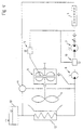
- the assembly according to the invention shown in FIG. 1 contains the following components, seen in the direction of the power flow from the engine during normal driving: A motor drive shaft 1, a primary shaft 2, a retarder 3, a turbo coupling 4, a secondary shaft 5 and the impeller 6 of a fan.
- Figure 1 is between the motor drive shaft 1 and the primary shaft 2 Provided gear, comprising two gears 1.1, 2.1.
- the primary wave is stored by means of two bearings 2.2.
- a bearing housing 2.3 is provided, also a seal 2.4.
- the retarder comprises a rotor 3.1 and a stator 3.2.
- the turbo coupling comprises a pump wheel 4.1 and a turbine wheel 4.2.
- Rotor 3.1 and Pump wheel 4.1 are connected to the primary shaft 2 in a rotationally fixed manner. At the same time they form a single component.
- a seal 7 is also provided the only component mentioned against a component not dealt with here Seals the housing.
- the secondary shaft 5 is mounted in bearings 5.2. It's a turn again Bearing housing 5.3 is provided, as is a seal 5.4.
- FIG. 2 shows only relatively minor ones Differences from that of Figure 1. These mainly exist in the arrangement of the bearings 2.2 and the bearing housing 2.3.
- the gear 2.1 is thus arranged to the left of the bearing 2.2 with the bearing housing 2.3.
- According to rotor 3.1 and pump wheel 4.1 are mounted "on the left".
- the storage is again somewhat different.
- the two camps 2.2 are on both sides of the Drive pinion 2.1.
- the bearing housing 2.3 encompasses the drive pinion 2.1.
- rotor 3.1 and pump wheel 4.1 are mounted "on the left”.
- the return flow of the working medium from the turbo coupling 4 is between Cooler 12 and pump 8 initiated, thus relatively low at one point Pressure.
Landscapes
- Engineering & Computer Science (AREA)
- Physics & Mathematics (AREA)
- Fluid Mechanics (AREA)
- Transportation (AREA)
- Mechanical Engineering (AREA)
- Braking Arrangements (AREA)
- Valve-Gear Or Valve Arrangements (AREA)
- Cylinder Crankcases Of Internal Combustion Engines (AREA)
Abstract

Description
- Fig. 1-3
- zeigen jeweils eine Ausführungsform einer erfindungsgemäßen Baugruppe.
- Fig. 4 u.5
- zeigen jeweils ein Steuerschema, das eine erfindungsgemäße Baugruppe enthält.
Eine Motorantriebswelle 1, eine Primärwelle 2, einen Retarder 3, eine Turbokupplung 4, eine Sekundärwelle 5 sowie das Laufrad 6 eines Lüfters.
Claims (14)
- Baugruppe für eine Brennkraftmaschine (1);1.1 mit einer Primärwelle (2);1.2 mit einer Sekundärwelle (5);1.3 mit einem hydrodynamischen Retarder (3), umfassend einen Rotor (3.1) und einen Stator (3.2);1.4 mit einer Kupplung (4), umfassend ein Primärteil (4.1) und ein Sekundärteil (4.2);1.5 der Rotor (3.1) des Retarders (3) und das Primärteil (4.1) der Kupplung (4) sind von der Primärwelle (2) angetrieben;1.6 das Sekundärteil (4.2) der Kupplung (4) und das Laufrad (6) eines Hilfsaggregates stehen mit der Sekundärwelle (5) in Triebverbindung.
- Baugruppe nach Anspruch 1, dadurch gekennzeichnet, daß die Kupplung (4) eine Turbokupplung (4) mit einem Primärrad und einem Sekundärrad ist.
- Baugruppe nach Anspruch 1 oder 2, dadurch gekennzeichnet, daß Primärwelle (2) und Sekundärwelle (5) koaxial zueinander angeordnet sind.
- Baugruppe nach einem der Ansprüche 1 bis 3, dadurch gekennzeichnet, daß Gehäuseteile von Retarder (3) und Kupplung (4) baulich miteinander vereinigt sind.
- Baugruppe nach einem der Ansprüche 1 bis 4, dadurch gekennzeichnet, daß das Laufrad einer Pumpe (8) ebenfalls mit der Primärwelle (2) in Triebverbindung steht.
- Baugruppe nach einem der Ansprüche 1 bis 5, dadurch gekennzeichnet, daß zwischen der Primärwelle (2) und dem Rotor (3.1) des Retarders (3) ein Hochgang geschaltet ist.
- Baugruppe nach einem der Ansprüche 1 bis 6, dadurch gekennzeichnet, daß der Rotor (3.1) des Retarders (3) und das Primärteil(4.1) der Kupplung (4) baulich miteinander vereinigt sind.
- Baugruppe nach einem der Ansprüche 1 bis 7, dadurch gekennzeichnet, daß wenigstens zwei der drei Aggregate - Retarder (3), Kupplung (4), Pumpe (8) - ein und dasselbe Arbeitsmedium verwenden.
- Baugruppe nach einem der Ansprüche 1 bis 8, dadurch gekennzeichnet, daß zwischen der Brennkraftmaschine (1) und der Primärwelle (2) ein Hochgang (1.1, 2.1) geschaltet ist.
- Baugruppe nach Anspruch 9, dadurch gekennzeichnet, daß der Hochgang zwischen der Hauptwelle der Brennkraftmaschine (1) und der Primärwelle (2) geschaltet ist.
- Baugruppe nach einem der Ansprüche 1 bis 10, dadurch gekennzeichnet, daß wenigstens eines der folgenden Aggregate - Hochgang, Retarder (3), Kupplung (4) - schaltbar oder regelbar ist.
- Baugruppe nach einem der Ansprüche 1 bis 11, dadurch gekennzeichnet, daß zwei Kupplungen unterschiedlicher Bauarten vorgesehen sind.
- Baugruppe nach einem der Ansprüche 1 bis 12, dadurch gekennzeichnet durch die Anordnung zwischen der Frontpartie der Brennkraftmaschine (1) und einem Kühler(12).
- Baugruppe nach einem der Ansprüche 1 bis 13, dadurch gekennzeichnet, daß das Hilfsaggregat das Laufrad (6) eines Lüfters ist.
Applications Claiming Priority (2)
| Application Number | Priority Date | Filing Date | Title |
|---|---|---|---|
| DE19939726 | 1999-08-21 | ||
| DE19939726A DE19939726A1 (de) | 1999-08-21 | 1999-08-21 | Baugruppe für eine Brennkraftmaschine |
Publications (2)
| Publication Number | Publication Date |
|---|---|
| EP1081003A1 true EP1081003A1 (de) | 2001-03-07 |
| EP1081003B1 EP1081003B1 (de) | 2002-07-31 |
Family
ID=7919176
Family Applications (1)
| Application Number | Title | Priority Date | Filing Date |
|---|---|---|---|
| EP00117619A Expired - Lifetime EP1081003B1 (de) | 1999-08-21 | 2000-08-16 | Baugruppe für eine Brennkraftmaschine |
Country Status (3)
| Country | Link |
|---|---|
| EP (1) | EP1081003B1 (de) |
| AT (1) | ATE221477T1 (de) |
| DE (2) | DE19939726A1 (de) |
Cited By (6)
| Publication number | Priority date | Publication date | Assignee | Title |
|---|---|---|---|---|
| EP1264748A1 (de) * | 2001-06-08 | 2002-12-11 | South West Research Patents Pty Ltd | Retardersystem für Fahrzeuge |
| WO2005068800A1 (de) * | 2004-01-15 | 2005-07-28 | Voith Turbo Gmbh & Co. Kg | Antriebskraftübertragungsvorrichtung mit hydrodynamischer gegenlaufkupplung |
| WO2007107314A1 (de) * | 2006-03-22 | 2007-09-27 | Voith Turbo Gmbh & Co. Kg | Hydrodynamische baugruppe mit einem retarder und einer hydrodynamischen kupplung |
| DE102007013489A1 (de) * | 2007-03-21 | 2008-09-25 | Zf Friedrichshafen Ag | Dichteinrichtung zum Abdichten eines Retarders |
| DE102004016904B4 (de) * | 2004-04-06 | 2012-08-09 | Man Truck & Bus Ag | Anordnung und Verfahren zur Ankopplung eines Luftpressers an die Antriebswelle einer Brennkraftmaschine |
| CN109715985A (zh) * | 2016-09-13 | 2019-05-03 | 福伊特专利有限公司 | 用于轨道车辆的液力传动器 |
Families Citing this family (4)
| Publication number | Priority date | Publication date | Assignee | Title |
|---|---|---|---|---|
| DE102008034973A1 (de) * | 2008-07-25 | 2010-01-28 | Voith Patent Gmbh | Kühlsystem, insbesondere eines Kraftfahrzeuges |
| DE102010051717A1 (de) | 2010-11-19 | 2012-05-24 | Voith Patent Gmbh | Antriebsstrang mit einem hydrodynamischen Retarder und Verfahren zum Einstellen des Bremsmomentes |
| DE102010051715A1 (de) | 2010-11-19 | 2012-05-24 | Voith Patent Gmbh | Antriebsstrang mit einem hydrodynamischen Retarder |
| DE102019105047A1 (de) * | 2019-02-28 | 2020-09-03 | Voith Patent Gmbh | Drehrichtungsneutrale hydrodynamische Bremse |
Citations (5)
| Publication number | Priority date | Publication date | Assignee | Title |
|---|---|---|---|---|
| FR1521399A (fr) * | 1967-01-18 | 1968-04-19 | Labavia | Perfectionnements aux transmissions de véhicules équipés de ralentisseurs et à leurs dispositifs de commande |
| DE2112742A1 (de) * | 1971-03-17 | 1972-09-28 | Voith Getriebe Kg | Kuehlvorrichtung fuer eine hydrodynamische Bremse |
| GB1394450A (en) * | 1971-12-04 | 1975-05-14 | Kloeckner Humboldt Deutz Ag | Power unit for vehicles including an air-cooled internal combustion engine and an hydrodynamic brake |
| US4191072A (en) * | 1976-12-15 | 1980-03-04 | Zahnradfabrik Friedrichshafen Ag | Transmission with hydrodynamic torque converter and retarder |
| EP0716966A2 (de) * | 1994-12-16 | 1996-06-19 | Voith Turbo GmbH | Antriebseinheit |
Family Cites Families (8)
| Publication number | Priority date | Publication date | Assignee | Title |
|---|---|---|---|---|
| US2827133A (en) * | 1952-06-09 | 1958-03-18 | Schneider Brothers Company | Hydraulic turbo brake |
| DE1245790B (de) * | 1962-12-21 | 1967-07-27 | Ass Elect Ind | Umsteuerbares Schiffsgetriebe |
| DE1780591A1 (de) * | 1966-03-17 | 1970-07-16 | Glamann Dr Ing Paul Wilhelm | Anordnung eines hydrodynamischen Bremsgeraets an der Kraftuebertragung eines Antriebsblocks fuer Fahrzeuge,besonders fuer Nutzfahrzeuge |
| DE1625838A1 (de) * | 1967-11-11 | 1970-08-20 | Voith Getriebe Kg | Hydrodynamische Bremse |
| DE3229951C2 (de) * | 1981-02-12 | 1986-08-28 | J.M. Voith Gmbh, 7920 Heidenheim | Antriebsaggregat mit einer Antriebsmaschine und einer hydrodynamischen Bremse |
| DE3838404A1 (de) * | 1988-11-12 | 1990-05-17 | Bosch Gmbh Robert | Regeleinrichtung fuer den antrieb des luefters einer brennkraftmaschine |
| DE4041158C1 (de) * | 1990-12-21 | 1992-08-20 | Mercedes-Benz Aktiengesellschaft, 7000 Stuttgart, De | |
| US5482148A (en) * | 1994-08-26 | 1996-01-09 | General Motors Corporation | System for transmission overspeed and horsepower limit protection |
-
1999
- 1999-08-21 DE DE19939726A patent/DE19939726A1/de not_active Withdrawn
-
2000
- 2000-08-16 EP EP00117619A patent/EP1081003B1/de not_active Expired - Lifetime
- 2000-08-16 AT AT00117619T patent/ATE221477T1/de not_active IP Right Cessation
- 2000-08-16 DE DE50000330T patent/DE50000330D1/de not_active Expired - Lifetime
Patent Citations (5)
| Publication number | Priority date | Publication date | Assignee | Title |
|---|---|---|---|---|
| FR1521399A (fr) * | 1967-01-18 | 1968-04-19 | Labavia | Perfectionnements aux transmissions de véhicules équipés de ralentisseurs et à leurs dispositifs de commande |
| DE2112742A1 (de) * | 1971-03-17 | 1972-09-28 | Voith Getriebe Kg | Kuehlvorrichtung fuer eine hydrodynamische Bremse |
| GB1394450A (en) * | 1971-12-04 | 1975-05-14 | Kloeckner Humboldt Deutz Ag | Power unit for vehicles including an air-cooled internal combustion engine and an hydrodynamic brake |
| US4191072A (en) * | 1976-12-15 | 1980-03-04 | Zahnradfabrik Friedrichshafen Ag | Transmission with hydrodynamic torque converter and retarder |
| EP0716966A2 (de) * | 1994-12-16 | 1996-06-19 | Voith Turbo GmbH | Antriebseinheit |
Cited By (10)
| Publication number | Priority date | Publication date | Assignee | Title |
|---|---|---|---|---|
| EP1264748A1 (de) * | 2001-06-08 | 2002-12-11 | South West Research Patents Pty Ltd | Retardersystem für Fahrzeuge |
| WO2005068800A1 (de) * | 2004-01-15 | 2005-07-28 | Voith Turbo Gmbh & Co. Kg | Antriebskraftübertragungsvorrichtung mit hydrodynamischer gegenlaufkupplung |
| CN100430579C (zh) * | 2004-01-15 | 2008-11-05 | 福伊特涡轮机两合公司 | 具有液力对向耦合器的驱动力传递装置 |
| US7647851B2 (en) | 2004-01-15 | 2010-01-19 | Voith Turbo Gmbh & Co. Kg | Propulsion power transmission device with a hydrodynamic reverse clutch |
| DE102004016904B4 (de) * | 2004-04-06 | 2012-08-09 | Man Truck & Bus Ag | Anordnung und Verfahren zur Ankopplung eines Luftpressers an die Antriebswelle einer Brennkraftmaschine |
| WO2007107314A1 (de) * | 2006-03-22 | 2007-09-27 | Voith Turbo Gmbh & Co. Kg | Hydrodynamische baugruppe mit einem retarder und einer hydrodynamischen kupplung |
| DE102007013489A1 (de) * | 2007-03-21 | 2008-09-25 | Zf Friedrichshafen Ag | Dichteinrichtung zum Abdichten eines Retarders |
| EP1972515A3 (de) * | 2007-03-21 | 2011-01-26 | ZF Friedrichshafen AG | Dichteinrichtung zum Abdichten eines Retarders |
| CN109715985A (zh) * | 2016-09-13 | 2019-05-03 | 福伊特专利有限公司 | 用于轨道车辆的液力传动器 |
| CN109715985B (zh) * | 2016-09-13 | 2022-05-13 | 福伊特专利有限公司 | 用于轨道车辆的液力传动器 |
Also Published As
| Publication number | Publication date |
|---|---|
| DE50000330D1 (de) | 2002-09-05 |
| ATE221477T1 (de) | 2002-08-15 |
| DE19939726A1 (de) | 2001-03-22 |
| EP1081003B1 (de) | 2002-07-31 |
Similar Documents
| Publication | Publication Date | Title |
|---|---|---|
| DE102004002215B3 (de) | Antriebskraftübertragungsvorrichtung mit hydrodynamischer Gegenlaufkupplung | |
| DE2951961A1 (de) | Getriebeabdeckung | |
| DE102010051715A1 (de) | Antriebsstrang mit einem hydrodynamischen Retarder | |
| EP1081003B1 (de) | Baugruppe für eine Brennkraftmaschine | |
| DE102004060417B4 (de) | Kompakter Schraubenkompressor zum mobilen Einsatz in einem Fahrzeug | |
| DE102014220377A1 (de) | Hybrid-Kühlmittelpumpe | |
| DE4108658A1 (de) | Kraftfahrzeug mit einem einem zahnraederwechselgetriebe nachgeschalteten, hydrodynamischen retarder | |
| DE60202606T2 (de) | Gasturbinenanordnung | |
| EP0835993A2 (de) | Antriebseinheit mit einem Motor, einem Getriebe und einer Wasserpumpe | |
| DE102018127710A1 (de) | Elektrische Antriebseinheit sowie Antriebsanordnung für eine elektrische Antriebseinheit | |
| WO2006079386A1 (de) | Turbo-compound-system | |
| EP0085889A1 (de) | Zwei-oder mehrstufige Drehkolbenmaschine | |
| EP0445407B1 (de) | Antriebs-Aggregat, insbesondere zum Antrieb eines Fahrzeuges | |
| EP1079085A2 (de) | Brennkraftmaschine zum Antrieb eines Kraftfahrzeuges | |
| WO2010066520A1 (de) | Brennkraftmaschine mit einem nebenaggregatetrieb | |
| DE29522268U1 (de) | Querantrieb | |
| DE102015219204A1 (de) | Mehrfachpumpe und Getriebe | |
| DE102015008721A1 (de) | Lüfterantrieb für ein Kraftfahrzeug | |
| DE10149388A1 (de) | Fluidpumpe, insbesondere Hydraulik- oder Schmiermittelpumpe, für eine Brennkraftmaschine, sowie Baueinheit aus mindestens zwei Fluidpumpen für eine Brennkraftmaschine | |
| DE19544189A1 (de) | Antriebseinheit | |
| EP3494038B1 (de) | Unterseebootantriebssystem | |
| EP0880217A2 (de) | Baueinheit aus Verbrennungsmotor, Generator und Pumpenaggregat | |
| EP0835992A2 (de) | Antriebseinheit, insbesondere für ein Kraftfahrzeug | |
| DE102010015564A1 (de) | Brennkraftmaschine für ein Kraftfahrzeug | |
| DE10326887A1 (de) | Mehrstufiges Ölpumpensystem |
Legal Events
| Date | Code | Title | Description |
|---|---|---|---|
| PUAI | Public reference made under article 153(3) epc to a published international application that has entered the european phase |
Free format text: ORIGINAL CODE: 0009012 |
|
| AK | Designated contracting states |
Kind code of ref document: A1 Designated state(s): AT BE CH CY DE DK ES FI FR GB GR IE IT LI LU MC NL PT SE |
|
| AX | Request for extension of the european patent |
Free format text: AL;LT;LV;MK;RO;SI |
|
| 17P | Request for examination filed |
Effective date: 20010404 |
|
| 17Q | First examination report despatched |
Effective date: 20010529 |
|
| AKX | Designation fees paid |
Free format text: AT BE CH CY DE DK ES FI FR GB GR IE IT LI LU MC NL PT SE |
|
| GRAG | Despatch of communication of intention to grant |
Free format text: ORIGINAL CODE: EPIDOS AGRA |
|
| GRAG | Despatch of communication of intention to grant |
Free format text: ORIGINAL CODE: EPIDOS AGRA |
|
| GRAH | Despatch of communication of intention to grant a patent |
Free format text: ORIGINAL CODE: EPIDOS IGRA |
|
| GRAH | Despatch of communication of intention to grant a patent |
Free format text: ORIGINAL CODE: EPIDOS IGRA |
|
| GRAA | (expected) grant |
Free format text: ORIGINAL CODE: 0009210 |
|
| AK | Designated contracting states |
Kind code of ref document: B1 Designated state(s): AT BE CH CY DE DK ES FI FR GB GR IE IT LI LU MC NL PT SE |
|
| PG25 | Lapsed in a contracting state [announced via postgrant information from national office to epo] |
Ref country code: GB Free format text: LAPSE BECAUSE OF FAILURE TO SUBMIT A TRANSLATION OF THE DESCRIPTION OR TO PAY THE FEE WITHIN THE PRESCRIBED TIME-LIMIT Effective date: 20020731 Ref country code: GR Free format text: LAPSE BECAUSE OF FAILURE TO SUBMIT A TRANSLATION OF THE DESCRIPTION OR TO PAY THE FEE WITHIN THE PRESCRIBED TIME-LIMIT Effective date: 20020731 Ref country code: FI Free format text: LAPSE BECAUSE OF FAILURE TO SUBMIT A TRANSLATION OF THE DESCRIPTION OR TO PAY THE FEE WITHIN THE PRESCRIBED TIME-LIMIT Effective date: 20020731 Ref country code: IE Free format text: LAPSE BECAUSE OF FAILURE TO SUBMIT A TRANSLATION OF THE DESCRIPTION OR TO PAY THE FEE WITHIN THE PRESCRIBED TIME-LIMIT Effective date: 20020731 |
|
| REF | Corresponds to: |
Ref document number: 221477 Country of ref document: AT Date of ref document: 20020815 Kind code of ref document: T |
|
| REG | Reference to a national code |
Ref country code: CH Ref legal event code: EP Ref country code: GB Ref legal event code: FG4D Free format text: NOT ENGLISH |
|
| PG25 | Lapsed in a contracting state [announced via postgrant information from national office to epo] |
Ref country code: LU Free format text: LAPSE BECAUSE OF NON-PAYMENT OF DUE FEES Effective date: 20020816 Ref country code: AT Free format text: LAPSE BECAUSE OF NON-PAYMENT OF DUE FEES Effective date: 20020816 |
|
| PG25 | Lapsed in a contracting state [announced via postgrant information from national office to epo] |
Ref country code: BE Free format text: LAPSE BECAUSE OF NON-PAYMENT OF DUE FEES Effective date: 20020831 Ref country code: CY Free format text: LAPSE BECAUSE OF FAILURE TO SUBMIT A TRANSLATION OF THE DESCRIPTION OR TO PAY THE FEE WITHIN THE PRESCRIBED TIME-LIMIT Effective date: 20020831 |
|
| REG | Reference to a national code |
Ref country code: IE Ref legal event code: FG4D Free format text: GERMAN |
|
| REF | Corresponds to: |
Ref document number: 50000330 Country of ref document: DE Date of ref document: 20020905 |
|
| PG25 | Lapsed in a contracting state [announced via postgrant information from national office to epo] |
Ref country code: DK Free format text: LAPSE BECAUSE OF FAILURE TO SUBMIT A TRANSLATION OF THE DESCRIPTION OR TO PAY THE FEE WITHIN THE PRESCRIBED TIME-LIMIT Effective date: 20021031 |
|
| PG25 | Lapsed in a contracting state [announced via postgrant information from national office to epo] |
Ref country code: PT Free format text: LAPSE BECAUSE OF FAILURE TO SUBMIT A TRANSLATION OF THE DESCRIPTION OR TO PAY THE FEE WITHIN THE PRESCRIBED TIME-LIMIT Effective date: 20021118 |
|
| GBV | Gb: ep patent (uk) treated as always having been void in accordance with gb section 77(7)/1977 [no translation filed] |
Effective date: 20020731 |
|
| PG25 | Lapsed in a contracting state [announced via postgrant information from national office to epo] |
Ref country code: ES Free format text: LAPSE BECAUSE OF FAILURE TO SUBMIT A TRANSLATION OF THE DESCRIPTION OR TO PAY THE FEE WITHIN THE PRESCRIBED TIME-LIMIT Effective date: 20030130 |
|
| ET | Fr: translation filed | ||
| BERE | Be: lapsed |
Owner name: *MAN NUTZFAHRZEUGE A.G. Effective date: 20020831 Owner name: *VOITH TURBO G.M.B.H. & CO. K.G. Effective date: 20020831 |
|
| PG25 | Lapsed in a contracting state [announced via postgrant information from national office to epo] |
Ref country code: MC Free format text: LAPSE BECAUSE OF NON-PAYMENT OF DUE FEES Effective date: 20030301 |
|
| REG | Reference to a national code |
Ref country code: IE Ref legal event code: FD4D Ref document number: 1081003E Country of ref document: IE |
|
| PLBE | No opposition filed within time limit |
Free format text: ORIGINAL CODE: 0009261 |
|
| STAA | Information on the status of an ep patent application or granted ep patent |
Free format text: STATUS: NO OPPOSITION FILED WITHIN TIME LIMIT |
|
| 26N | No opposition filed |
Effective date: 20030506 |
|
| PGFP | Annual fee paid to national office [announced via postgrant information from national office to epo] |
Ref country code: FR Payment date: 20030814 Year of fee payment: 4 |
|
| PGFP | Annual fee paid to national office [announced via postgrant information from national office to epo] |
Ref country code: SE Payment date: 20030820 Year of fee payment: 4 |
|
| PG25 | Lapsed in a contracting state [announced via postgrant information from national office to epo] |
Ref country code: SE Free format text: LAPSE BECAUSE OF NON-PAYMENT OF DUE FEES Effective date: 20040817 |
|
| PG25 | Lapsed in a contracting state [announced via postgrant information from national office to epo] |
Ref country code: CH Free format text: LAPSE BECAUSE OF NON-PAYMENT OF DUE FEES Effective date: 20040831 Ref country code: LI Free format text: LAPSE BECAUSE OF NON-PAYMENT OF DUE FEES Effective date: 20040831 |
|
| PG25 | Lapsed in a contracting state [announced via postgrant information from national office to epo] |
Ref country code: NL Free format text: LAPSE BECAUSE OF NON-PAYMENT OF DUE FEES Effective date: 20050301 |
|
| EUG | Se: european patent has lapsed | ||
| REG | Reference to a national code |
Ref country code: CH Ref legal event code: PL |
|
| PG25 | Lapsed in a contracting state [announced via postgrant information from national office to epo] |
Ref country code: FR Free format text: LAPSE BECAUSE OF NON-PAYMENT OF DUE FEES Effective date: 20050429 |
|
| NLV4 | Nl: lapsed or anulled due to non-payment of the annual fee |
Effective date: 20050301 |
|
| REG | Reference to a national code |
Ref country code: FR Ref legal event code: ST |
|
| PG25 | Lapsed in a contracting state [announced via postgrant information from national office to epo] |
Ref country code: IT Free format text: LAPSE BECAUSE OF NON-PAYMENT OF DUE FEES Effective date: 20050816 |
|
| REG | Reference to a national code |
Ref country code: DE Ref legal event code: R081 Ref document number: 50000330 Country of ref document: DE Owner name: VOITH TURBO GMBH & CO. KG, DE Free format text: FORMER OWNERS: VOITH TURBO GMBH & CO. KG, 89522 HEIDENHEIM, DE; MAN NUTZFAHRZEUGE AG, 80995 MUENCHEN, DE Effective date: 20110818 Ref country code: DE Ref legal event code: R081 Ref document number: 50000330 Country of ref document: DE Owner name: MAN TRUCK & BUS AG, DE Free format text: FORMER OWNERS: VOITH TURBO GMBH & CO. KG, 89522 HEIDENHEIM, DE; MAN NUTZFAHRZEUGE AG, 80995 MUENCHEN, DE Effective date: 20110818 Ref country code: DE Ref legal event code: R081 Ref document number: 50000330 Country of ref document: DE Owner name: MAN TRUCK & BUS AG, DE Free format text: FORMER OWNER: VOITH TURBO GMBH & CO. KG, MAN NUTZFAHRZEUGE AG, , DE Effective date: 20110818 Ref country code: DE Ref legal event code: R082 Ref document number: 50000330 Country of ref document: DE Representative=s name: DR. WEITZEL & PARTNER PATENT- UND RECHTSANWAEL, DE Effective date: 20110818 Ref country code: DE Ref legal event code: R081 Ref document number: 50000330 Country of ref document: DE Owner name: VOITH TURBO GMBH & CO. KG, DE Free format text: FORMER OWNER: VOITH TURBO GMBH & CO. KG, MAN NUTZFAHRZEUGE AG, , DE Effective date: 20110818 |
|
| REG | Reference to a national code |
Ref country code: DE Ref legal event code: R082 Ref document number: 50000330 Country of ref document: DE Representative=s name: DR. WEITZEL & PARTNER PATENT- UND RECHTSANWAEL, DE Ref country code: DE Ref legal event code: R081 Ref document number: 50000330 Country of ref document: DE Owner name: MAN TRUCK & BUS SE, DE Free format text: FORMER OWNERS: MAN TRUCK & BUS AG, 80995 MUENCHEN, DE; VOITH TURBO GMBH & CO. KG, 89522 HEIDENHEIM, DE Ref country code: DE Ref legal event code: R081 Ref document number: 50000330 Country of ref document: DE Owner name: VOITH TURBO GMBH & CO. KG, DE Free format text: FORMER OWNERS: MAN TRUCK & BUS AG, 80995 MUENCHEN, DE; VOITH TURBO GMBH & CO. KG, 89522 HEIDENHEIM, DE |
|
| PGFP | Annual fee paid to national office [announced via postgrant information from national office to epo] |
Ref country code: DE Payment date: 20190830 Year of fee payment: 20 |
|
| REG | Reference to a national code |
Ref country code: DE Ref legal event code: R071 Ref document number: 50000330 Country of ref document: DE |