EP1081018B1 - Méthode et dispositif pour la reproduction d'un couplage mécanique - Google Patents
Méthode et dispositif pour la reproduction d'un couplage mécanique Download PDFInfo
- Publication number
- EP1081018B1 EP1081018B1 EP00115284A EP00115284A EP1081018B1 EP 1081018 B1 EP1081018 B1 EP 1081018B1 EP 00115284 A EP00115284 A EP 00115284A EP 00115284 A EP00115284 A EP 00115284A EP 1081018 B1 EP1081018 B1 EP 1081018B1
- Authority
- EP
- European Patent Office
- Prior art keywords
- actuator
- torque
- actuated
- force
- coupling
- Prior art date
- Legal status (The legal status is an assumption and is not a legal conclusion. Google has not performed a legal analysis and makes no representation as to the accuracy of the status listed.)
- Expired - Lifetime
Links
- 230000008878 coupling Effects 0.000 title claims abstract description 66
- 238000010168 coupling process Methods 0.000 title claims abstract description 66
- 238000005859 coupling reaction Methods 0.000 title claims abstract description 66
- 238000000034 method Methods 0.000 title claims abstract description 13
- 239000011159 matrix material Substances 0.000 claims description 19
- 230000005540 biological transmission Effects 0.000 claims description 15
- 238000006243 chemical reaction Methods 0.000 description 6
- 230000000694 effects Effects 0.000 description 5
- 230000001419 dependent effect Effects 0.000 description 4
- 238000010586 diagram Methods 0.000 description 3
- 230000007613 environmental effect Effects 0.000 description 3
- 238000004088 simulation Methods 0.000 description 2
- 239000000654 additive Substances 0.000 description 1
- 230000000996 additive effect Effects 0.000 description 1
- 238000013016 damping Methods 0.000 description 1
- 230000000704 physical effect Effects 0.000 description 1
- 230000003068 static effect Effects 0.000 description 1
- 230000001629 suppression Effects 0.000 description 1
Images


Classifications
-
- B—PERFORMING OPERATIONS; TRANSPORTING
- B62—LAND VEHICLES FOR TRAVELLING OTHERWISE THAN ON RAILS
- B62D—MOTOR VEHICLES; TRAILERS
- B62D5/00—Power-assisted or power-driven steering
- B62D5/001—Mechanical components or aspects of steer-by-wire systems, not otherwise provided for in this maingroup
- B62D5/005—Mechanical components or aspects of steer-by-wire systems, not otherwise provided for in this maingroup means for generating torque on steering wheel or input member, e.g. feedback
- B62D5/006—Mechanical components or aspects of steer-by-wire systems, not otherwise provided for in this maingroup means for generating torque on steering wheel or input member, e.g. feedback power actuated
-
- B—PERFORMING OPERATIONS; TRANSPORTING
- B62—LAND VEHICLES FOR TRAVELLING OTHERWISE THAN ON RAILS
- B62D—MOTOR VEHICLES; TRAILERS
- B62D6/00—Arrangements for automatically controlling steering depending on driving conditions sensed and responded to, e.g. control circuits
- B62D6/008—Control of feed-back to the steering input member, e.g. simulating road feel in steer-by-wire applications
Definitions
- the invention relates to a method and a device for simulating a mechanical coupling according to the preamble of claims 1 and 8, respectively.
- a mechanical coupling between a control element and an element to be actuated has some disadvantages.
- the coupling size be difficult and structurally complicated between the two elements.
- constructive problems may arise because the mechanical connection between the two elements must be made spatially.
- a steering system conventionally used for a steering column which not only represents a potential hazard in an accident, but miss a desired variability with respect to the arrangement of a steering wheel in the vehicle interior.
- a known steering system without mechanical connection between a steering wheel and the steerable wheels will serve to further explain the invention.
- a vehicle operator inputs a desired steering angle via a steering wheel 10 fixed to a steering wheel shaft 11.
- the steering angle predetermined by the vehicle operator is detected by a steering angle sensor 12.
- a steering angle corresponding signal 14 is delivered to a controller 18.
- the controller 18 calculates due to the driver's desired steering angle and possibly other vehicle sizes, such.
- As the vehicle speed, a desired wheel angle generates a corresponding signal and passes this to a Radstellech 20 on.
- the Radstellech 20 acts on a shaft 21 which is connected to a steering gear 26.
- the steering gear 26 actuates the wheels 28 according to the output from the control unit 18 signal.
- a counter-torque or a counterforce is generated in the rule, which acts on the steering shaft 21 via the wheels 28 and the steering gear 26.
- This counterforce (or counter torque) is detected by a counter force sensor 22 and reported back in the form of a corresponding counter force signal 24 to the control unit.
- the control unit generates at least from the counterforce signal 24 a restoring moment and communicates this with a torque setting unit 16, which is connected to the steering wheel shaft 11.
- This feedback gives the driver, despite mechanically decoupled steering feedback on the forces acting on the wheels forces and moments and thus on the driving situation. This information is crucial for safe vehicle guidance. Based on the feedback, the driver can assess the driving situation and assess whether he is in a critical or non-critical driving situation, whether he drives a curve quickly or slowly, etc.
- a device for controlling the steering angle of a motor vehicle in which a steering angle setpoint value is specified as a function of a steering angle force and the vehicle speed.
- DE 196 07 028 A1 relates to a steering system for a non-track-bound vehicle in which a restoring torque for a steering wheel is calculated as a function of the steering angle and a steering angle speed on the steering wheel.
- a driving speed-dependent coefficient is used.
- This system corresponds to an emulation of an artificial spring-damper element for imparting a driving feeling. A real feedback of a bike / road contact does not take place.
- DE 198 04 821 A1 describes a steering control device for turning steered wheels in accordance with the rotation of a mechanically decoupled steering wheel, wherein the steering control device comprises a steering angle detecting unit for detecting the steering angle, a steering force detecting means for detecting the steering force applied to the steering shaft, a rotational reaction force detecting means for detecting a rotational reaction force applied to the steered wheel and rotational amount detecting means for detecting the rotational amount of the steered wheel.
- the steering shaft is driven by a steering shaft drive based on a force proportional to the steering force, the rotational reaction force and a deviation between a target control amount based on the steering angle and the amount of rotation, thereby undesirably occurring in the initial state of steering Increase in the deviation between the force proportional to the steering force and the rotational reaction force to be reduced.
- a restoring torque is calculated as a function of the driving speed, a motor current of a wheel angle adjusting unit, the outside temperature, a windscreen wiper switch and an ultrasonic sensor. Also, this system is only an artificial spring-damper system over which no sufficiently authentic feedback can be conveyed.
- the object of the invention is to provide a method and a device of the type mentioned, in which an authentic feedback effect is achieved by a real image of a mechanical coupling to be emulated.
- a key idea of the invention is to be seen in that the present at a mechanical coupling between a control element and an element to be actuated coupling is simulated with the aid of a control device between the two actuators.
- the size of a mechanical coupling to be simulated between an operating element and an element to be actuated is predetermined. Then, from this size and taking into account the couplings between the actuator and the control element as well determines an actuator coupling size between the actuator and the element to be actuated.
- the Aktuatorkopplungs lymph defines exactly that coupling size between the two actuators, which is necessary to give the nachzubende mechanical coupling together with the couplings between the first actuator and the control element and the second actuator and the element to be actuated.
- At least one control variable for at least one of the two actuators is determined.
- an authentic replica of a mechanical coupling to be emulated is achieved, in particular with regard to the elasticity behavior in the overall system.
- an operator of the operating element can also recognize no difference to a conventional feedback.
- a vehicle operator does not have to adjust to a different feel when operating a vehicle when switching from a conventional system to a "by-wire" system.
- the present invention can be applied to any hitherto mechanical couplings which, however, are now to be realized without direct mechanical connection and in which feedback is necessary to inform the operator of forces or moments acting on the element to be actuated.
- transmission matrices are used that define coupling quantities between angles and moments of actuators.
- the Aktuatorkopplungs bulge must be calculated so that in combination with other coupling matrices between the actuators and the control element on the one hand or the element to be actuated on the other hand a nachzubende mechanical coupling Z LS is achieved.
- claims 2 and 9 are placed on an application in a steering system.
- the quantities ⁇ AM and ⁇ AM which represent angles or moments according to claims 2 and 9, can also be lengths or forces. In this way, the invention can be applied not only to rotary but also to length actuators.
- the coupling to be achieved between the control element and actuated element can be changed in a desired manner or superimposed with another moment.
- the size it is possible to make the size to be specified dependent on input parameters such as the vehicle speed for the mechanical coupling to be simulated.
- the mechanical coupling changes according to the input variable used, allowing the simulation of various effects.
- the steering ratio is used to improve comfort, in which the ratio between a steering wheel angle ⁇ LR and a steering gear angle ⁇ LG or even a torque ratio, ie the ratio between steering wheel torque ⁇ LR and steering gear torque ⁇ LR can be changed.
- the steering wheel torque can also be selected in dependence on the steering wheel or steering gear angle. This could be mechanical to the authentic acting system superimposed on an artificial spring-damping system, which causes an effect as in DE 196 07 028 C1 in an additive manner.
- a Vorhalteglied can be used, with which the steering input of the driver is filtered on the control.
- the reaction of the vehicle can be accelerated to a steering specification (Vorlenk steering).
- a steering angle specification can be calculated from other variables, such as the yaw rate of the vehicle. This measure could be used to compensate for time and environmental influences.
- a local moment or force circuit in a module of the element to be actuated.
- a high-pass behavior is chosen in order not to jeopardize the stationary accuracy of the control.
- Static friction effects in the steering gear can also be simulated by non-linear consideration in the generation of the actuator coupling size or the control variable.
- FIG. 2 schematically shows a steering system with a control unit 10 in the form of a steering wheel, which is mechanically connected to a steering column 50.
- the steering column 50 in turn is mechanically coupled via a pinion 40 with a steering gear 26, which is designed for the deflection of steerable wheels 28 in a known manner.
- Fig. 3 differs from Fig. 2 only in that a vehicle steering system is described with servo assistance, which is expressed in the stiffness parameter C LS and an additional assistance torque ⁇ LS .
- FIG. 4 shows by way of example two characteristic curves of the assistance torque ⁇ LS as a function of the steering wheel torque ⁇ LR , namely for two different vehicle speeds.
- FIG. 5 differs from FIGS. 2 and 3 in that the operating unit 10 is mechanically decoupled from the steering gear 26.
- the coupling is realized via two actuators, namely a torque setting unit 16 and a wheel adjusting unit 20, which are electrically driven and deliver the torques generated by them to a steering wheel shaft 11 or a steering shaft 21 with the interposition of rigidities C LR or C LG .
- the two actuators that is to say the torque setting unit 16 and the wheel adjusting unit 20, are acted upon by a control unit 18 (cf., FIG. 1).
- a control unit 18 cf., FIG. 1
- transmission matrices are used for the representation of reaction equations, with angles and moments being used as reference variables in deviation from the usual representation as speed-force ratio.
- Z 11 describes the angular transmission
- Z 22 the torque transmission
- the sizes Z 12 and Z 21 represent the input and output stiffnesses.
- ⁇ R ⁇ L G + ( J R s 2 + d L G s ) ⁇ L G
- Fig. 4 two gain characteristics ⁇ LS are shown, representing the assist torque in response to the steering wheel torque ⁇ LR .
- the chosen speeds are a parking speed and a speed of v> 80 km / h.
- the steering column 50 is split into the steering wheel shaft 11 for the control unit 10 and the steering shaft 21 for the steering gear.
- Modules namely a steering wheel module, which includes the steering wheel shaft 11, the control element 10, the torsion bar 44 and the torque adjusting unit 16 and a steering gear module, which the steering pinion 40, the steering gear 26, the torsion bar 46, the wheel 20 and the wheels to be steered 28 comprises.
- the torque adjusting unit 16 for generating the steering feel on the control unit 10 is another torsion bar 44 of the rigidity C LR connected to the steering wheel shaft 11 and the operating element 10.
- the wheel-adjusting unit 20 for steering the steerable wheels 28 is likewise connected to the pinion 40 of the steering gear via a further torsion bar 46 with stiffness C LG (compare FIG. 5).
- the present invention provides an authentic replica of a driving feel, as in a mechanical steering with or without power steering or an authentic feedback.
- the present invention can be applied wherever a previously mechanical coupling between a control element and an element to be actuated is replaced by a mechanically decoupled connection, wherein feedback can not be dispensed with.
Landscapes
- Engineering & Computer Science (AREA)
- Chemical & Material Sciences (AREA)
- Combustion & Propulsion (AREA)
- Transportation (AREA)
- Mechanical Engineering (AREA)
- Steering Control In Accordance With Driving Conditions (AREA)
- Arrangement And Mounting Of Devices That Control Transmission Of Motive Force (AREA)
- Telephone Set Structure (AREA)
- Paper (AREA)
Claims (12)
- Procédé pour la reproduction d'un couplage mécanique entre un élément de manoeuvre (10) à actionner par un utilisateur et un élément à actionner (28) dans un véhicule, qui ne sont pas directement couplés mécaniquement entre eux, un premier actionneur électrique (16) appliquant un couple ou une force de rotation à l'élément de manoeuvre (10) et un deuxième actionneur électrique (20) appliquant un couple ou une force de rotation à l'élément à actionner (28), comprenant les étapes suivantes :- application d'un couple de rotation actif ou d'une force active à l'élément à actionner (28) par le deuxième actionneur électrique (20),- enregistrement du couple résistant (τLG) ou de la force antagoniste agissant sur l'élément à actionner (28),- calcul d'un couple de rotation de rétrocouplage ou d'une force de rétrocouplage en fonction du couple résistant ou de la force antagoniste,- application du couple de rotation de rétrocouplage ou de la force de rétrocouplage à l'élément de manoeuvre (10) par le premier actionneur électrique (16),caractérisé en ce qu'
on prédéfinit une grandeur sous la forme d'une matrice (ZLS, ZLSS) pour le couplage mécanique à reproduire entre l'élément de manoeuvre (10) et l'élément à actionner (28),
on détermine au moins une grandeur de couplage d'actionneurs à partir de la grandeur du couplage mécanique à reproduire et en tenant compte des couplages entre le premier actionneur (16) et l'élément de manoeuvre (10) ainsi qu'entre le deuxième actionneur (20) et l'élément à actionner (28), et
on détermine au moins une grandeur de commande pour le premier actionneur (16) au moins à partir de la ou des grandeurs de couplage d'actionneur et du couple résistant enregistré ou de la force antagoniste enregistrée. - Procédé selon la revendication 1,
caractérisé en ce qu'
on calcule comme grandeur de couplage d'actionneurs, une matrice de transmission ZReg qui définit le couplage entre les deux actionneurs (16, 20) selon
OÙ ϕAM définit un angle ou une longueur au niveau du premier actionneur, ϕBM un angle ou une longueur au niveau du deuxième actionneur, τAM un couple ou une force au niveau du premier actionneur et τBM un couple ou une force au niveau du deuxième actionneur,
en tenant compte de la condition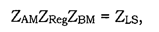
avec ZAM comme matrice de couplage entre l'élément de manoeuvre (10) et un premier actionneur (16), ZBM comme matrice de couplage entre l'élément à actionner (28) et le deuxième actionneur (20) et ZLS comme matrice d'un couplage mécanique à reproduire entre l'élément de manoeuvre (10) et l'élément à actionner (28), - Procédé selon l'une des revendications précédentes,
caractérisé en ce qu'
on détermine le couplage de telle sorte qu'il y a une transmission d'angle et/ou une transmission de couple ou de force entre les deux actionneurs. - Procédé selon la revendication 3,
caractérisé en ce qu'
on détermine la transmission d'angle, de couple ou de force en fonction de paramètres de fonctionnement du véhicule. - Procédé selon une des revendications précédentes,
caractérisé en ce que
la détermination de la ou des grandeurs de couplage d'actionneurs ou de la ou des grandeurs de commande tient compte de paramètres de fonctionnement du véhicule et/ ou de paramètres environnants. - Procédé selon la revendication 5,
caractérisé en ce qu'
comme paramètres de fonctionnement du véhicule ou de paramètre environnement, on utilise une grandeur d'actionnement de l'élément de manoeuvre (10), une vitesse du véhicule, l'état de la route ou un signal d'angle de lacet. - Procédé selon l'une des revendications précédentes,
caractérisé en ce que
pour éliminer les défaillances, on utilise un circuit de couple ou de force local dans un module de l'élément à actionner (28). - Dispositif pour la reproduction d'un couplage mécanique entre un élément de manoeuvre (10) à actionner par un utilisateur et un élément à actionner (28) dans un véhicule, qui ne sont pas directement couplés mécaniquement entre eux, avec
un premier actionneur électrique (16) couplé mécaniquement avec l'élément de manoeuvre (10),
un deuxième actionneur électrique (20) couplée mécaniquement avec l'élément à actionner (28),
un détecteur (22) pour enregistrer un couple résistant ou une force antagoniste sur l'élément à enregistrer (28), et
un dispositif de commande (18) relié aux deux actionneurs (16, 20) et qui commande ceux-ci en fonction du couple résistant enregistré ou de la force antagoniste enregistrée,
caractérisé en ce que
l'unité de commande (18) contient une grandeur pour le couplage mécanique à reproduire entre l'élément de manoeuvre (10) et l'élément à actionner (28) sous la forme d'une matrice (ZLS, ZLSS), ou le dispositif de commande (18) est conçu pour recevoir une telle grandeur,
l'unité de commande (18) est conçue pour calculer au moins une grandeur de couplage d'actionneurs sur la base de la grandeur du couplage mécanique à reproduire et en tenant compte des couplages entre le premier actionneur (16) et l'élément de manoeuvre (10) ainsi qu'entre le deuxième actionneur (20) et l'élément à actionner (28), et
l'unité de commande (18) est conçue pour déterminer au moins une grandeur de commande pour le premier actionneur (16) au moins à partir d'au moins une grandeur de couplage d'actionneurs et du couple résistant ou de la force antagoniste enregistrés. - Dispositif selon la revendication 8,
caractérisé en ce que
le couplage mécanique à reproduire sous la forme d'une matrice ZLS est enregistré dans le dispositif de commande (18) ou peut être transmis à celui-ci et une unité de calcul du dispositif de commande est conçue pour calculer une relation
où ϕAM représente un angle ou une longueur au niveau du premier actionneur, ϕBM un angle ou une longueur au niveau du deuxième actionneur, τAM un couple ou une force au niveau du premier actionneur et τBM un couple ou une force au niveau du deuxième actionneur,
en tenant compte de la condition
avec ZAM comme matrice de couplage entre l'élément de manoeuvre et le premier actionneur et ZBM comme matrice de couplage entre l'élément à actionner et le deuxième actionneur. - Dispositif selon l'une des revendications 8 ou 9,
caractérisé en ce que
le dispositif de commande (18) présente une unité de filtrage pour éliminer les défaillances. - Dispositif selon une des revendications 8 à 10,
caractérisé en ce que
l'appareil de commande (18) est conçu de sorte que la grandeur correspondant au couplage mécanique enregistrée dedans ou pouvant lui être transmise peut être modifiée en fonction de paramètres tels que la vitesse du véhicule, la vitesse de fonctionnement de l'élément de manoeuvre ou l'état de la route. - Dispositif selon l'une des revendications 8 à 11,
caractérisé en ce qu'
un circuit de couple ou de force local est prévu sur les côtés de l'élément à actionner (28) pour éliminer les défaillances.
Applications Claiming Priority (2)
| Application Number | Priority Date | Filing Date | Title |
|---|---|---|---|
| DE19940964 | 1999-08-28 | ||
| DE19940964A DE19940964B4 (de) | 1999-08-28 | 1999-08-28 | Verfahren und Vorrichtung zur Nachbildung einer mechanischen Kopplung |
Publications (3)
| Publication Number | Publication Date |
|---|---|
| EP1081018A2 EP1081018A2 (fr) | 2001-03-07 |
| EP1081018A3 EP1081018A3 (fr) | 2005-01-12 |
| EP1081018B1 true EP1081018B1 (fr) | 2006-09-13 |
Family
ID=7919980
Family Applications (1)
| Application Number | Title | Priority Date | Filing Date |
|---|---|---|---|
| EP00115284A Expired - Lifetime EP1081018B1 (fr) | 1999-08-28 | 2000-07-14 | Méthode et dispositif pour la reproduction d'un couplage mécanique |
Country Status (4)
| Country | Link |
|---|---|
| EP (1) | EP1081018B1 (fr) |
| AT (1) | ATE339340T1 (fr) |
| DE (2) | DE19940964B4 (fr) |
| ES (1) | ES2270765T3 (fr) |
Families Citing this family (8)
| Publication number | Priority date | Publication date | Assignee | Title |
|---|---|---|---|---|
| US7073622B2 (en) | 2004-06-15 | 2006-07-11 | Ford Global Technologies, Llc | On and off road steering ratios |
| DE102006017714B4 (de) * | 2006-04-15 | 2009-04-09 | Audi Ag | Verfahren zum kennlinien- oder kennfeldabhängigen Variieren des über ein Lenkrad eines aktiven oder semiaktiven Lenksystems oder über ein Pedal eines Kraftfahrzeugs aufzubringenden Lenk- oder Drehmoments |
| EP2934986B1 (fr) * | 2012-12-20 | 2018-05-30 | Volvo Truck Corporation | Procédé et agencement destinés à un système de direction électrique |
| JP7145389B2 (ja) * | 2018-10-09 | 2022-10-03 | 株式会社ジェイテクト | 操舵装置 |
| KR102660346B1 (ko) * | 2018-12-11 | 2024-04-23 | 현대자동차주식회사 | 전동식 조향시스템의 조향 제어방법 및 장치 |
| KR102719119B1 (ko) | 2019-06-24 | 2024-10-16 | 현대자동차주식회사 | 전동식 파워 조향 제어방법 및 제어시스템 |
| CN112572595A (zh) * | 2019-09-30 | 2021-03-30 | 比亚迪股份有限公司 | 方向盘的控制方法和系统、转向系统以及汽车 |
| CN112747895A (zh) * | 2020-12-29 | 2021-05-04 | 中国航天空气动力技术研究院 | 一种无位置反馈舵机的加载测试装置 |
Family Cites Families (7)
| Publication number | Priority date | Publication date | Assignee | Title |
|---|---|---|---|---|
| US4771846A (en) * | 1986-09-22 | 1988-09-20 | Trw Inc. | Apparatus for establishing steering feel |
| JP3521249B2 (ja) * | 1995-11-24 | 2004-04-19 | 光洋精工株式会社 | 自動車の舵取り装置 |
| DE19607028C1 (de) * | 1996-02-24 | 1997-08-21 | Daimler Benz Ag | Lenkung für nicht spurgebundenes Fahrzeug |
| JPH10203393A (ja) * | 1997-01-21 | 1998-08-04 | Koyo Seiko Co Ltd | 車両用操舵装置 |
| DE19702313C1 (de) * | 1997-01-23 | 1998-04-02 | Daimler Benz Ag | Einrichtung zur Steuerung des Lenkwinkels eines Kraftfahrzeuges |
| JP3517863B2 (ja) * | 1997-02-07 | 2004-04-12 | トヨタ自動車株式会社 | 操舵制御装置 |
| JP3627120B2 (ja) * | 1997-02-19 | 2005-03-09 | 光洋精工株式会社 | 車両用操舵装置 |
-
1999
- 1999-08-28 DE DE19940964A patent/DE19940964B4/de not_active Expired - Fee Related
-
2000
- 2000-07-14 EP EP00115284A patent/EP1081018B1/fr not_active Expired - Lifetime
- 2000-07-14 ES ES00115284T patent/ES2270765T3/es not_active Expired - Lifetime
- 2000-07-14 DE DE50013455T patent/DE50013455D1/de not_active Expired - Lifetime
- 2000-07-14 AT AT00115284T patent/ATE339340T1/de not_active IP Right Cessation
Also Published As
| Publication number | Publication date |
|---|---|
| DE50013455D1 (de) | 2006-10-26 |
| EP1081018A2 (fr) | 2001-03-07 |
| ES2270765T3 (es) | 2007-04-16 |
| DE19940964B4 (de) | 2005-08-11 |
| DE19940964A1 (de) | 2001-03-22 |
| ATE339340T1 (de) | 2006-10-15 |
| EP1081018A3 (fr) | 2005-01-12 |
Similar Documents
| Publication | Publication Date | Title |
|---|---|---|
| EP3856611B1 (fr) | Procédé pour déterminer une force exercée par une crémaillère d'un système de direction à commande par câble électrique, système de direction à commande par câble électrique et véhicule | |
| DE3610461C2 (de) | Lenkeinrichtung für ein Fahrzeug | |
| DE10332581B4 (de) | Fahrzeugfahrbedienungsvorrichtung mit einer Vorrichtung zum Bestimmen der Linearität einer Reifencharakteristik | |
| EP1373051B1 (fr) | Systeme de direction de vehicule pour la commande d'un angle de direction ou de braquage d'au moins une roue d'un vehicule | |
| EP3898383B1 (fr) | Procédé de détermination d'une sensation de direction d'un système de direction à commande électrique | |
| EP3943368B1 (fr) | Génération du couple de direction en tant que rétroaction haptique dans les systèmes de direction de véhicule | |
| DE19833189A1 (de) | Lenksystem für ein Fahrzeug | |
| DE112019001855B4 (de) | Fahrzeugsteuervorrichtung und eigenschaftsabschätzverfahren | |
| WO2019120699A1 (fr) | Procédé destiné à faire fonctionner un système de direction à orientation par câbles pour un véhicule automobile et système de direction pour un véhicule automobile | |
| EP4108544B1 (fr) | Direction par câble pour un véhicule automobile | |
| DE102019134568A1 (de) | Verfahren zum Betreiben einer Hilfskraftlenkung eines Fahrzeugs, Hilfskraftlenkung sowie Fahrzeug | |
| DE19601825B4 (de) | Lenksystem für ein Kraftfahrzeug | |
| DE102004001984B4 (de) | System und Verfahren zum Steuern bzw. Regeln eines elektronischen Fahrzeuglenkers unter Anwendung einer Verstärkungsplanungssteuerung bzw. Regelung | |
| DE19940964B4 (de) | Verfahren und Vorrichtung zur Nachbildung einer mechanischen Kopplung | |
| WO2024199568A1 (fr) | Procédé de génération d'une rétroaction de chaussée pour un conducteur de véhicule à partir d'excitations de chaussée basse fréquence d'un système de direction à commande électrique, et système de direction à commande électrique | |
| DE102005058200B4 (de) | Fahrzeuglenkgerät | |
| EP2977297B1 (fr) | Procede de determination d'un angle de direction d'un vehicule automobile, dispositif d'assistance et vehicule automobile | |
| DE60203755T2 (de) | Elektrische Servolenkung für ein Motorfahrzeug und dazu passendes Steuerungsverfahren | |
| DE10325484A1 (de) | Verfahren zum Lenken eines Fahrzeugs mit einer Überlagerungslenkung | |
| DE102020203212B4 (de) | Berücksichtigen von Handmomentenoffsets bei Fahrzeuglenksystem | |
| DE102010049580A1 (de) | Verfahren zum Betreiben eines Kraftwagens | |
| DE102024112908B3 (de) | Regelverfahren für ein Steer-By-Wire Lenksystem eines Kraftfahrzeugs | |
| DE102023201648B4 (de) | Steuergerät, Steer-by-Wire-Lenksystem und Verfahren zur Erzeugung eines Gegenmoments an einem Lenkrad eines Steer-by-Wire-Lenksystems | |
| DE102021110105A1 (de) | Verfahren zur Ansteuerung eines Aktuators zur Bereitstellung eines Force-Feedback-Moments an einem Lenkrad eines Steer-by-Wire Lenksystems | |
| DE102020201589B4 (de) | Verfahren zur Einstellung der Haptik einer Lenkungshandhabe in einem Steer-by-wire-Lenksystem und Steer-by-wire-Lenksystem |
Legal Events
| Date | Code | Title | Description |
|---|---|---|---|
| PUAI | Public reference made under article 153(3) epc to a published international application that has entered the european phase |
Free format text: ORIGINAL CODE: 0009012 |
|
| AK | Designated contracting states |
Kind code of ref document: A2 Designated state(s): AT BE CH CY DE DK ES FI FR GB GR IE IT LI LU MC NL PT SE |
|
| AX | Request for extension of the european patent |
Free format text: AL;LT;LV;MK;RO;SI |
|
| PUAL | Search report despatched |
Free format text: ORIGINAL CODE: 0009013 |
|
| AK | Designated contracting states |
Kind code of ref document: A3 Designated state(s): AT BE CH CY DE DK ES FI FR GB GR IE IT LI LU MC NL PT SE |
|
| AX | Request for extension of the european patent |
Extension state: AL LT LV MK RO SI |
|
| 17P | Request for examination filed |
Effective date: 20050503 |
|
| AKX | Designation fees paid |
Designated state(s): AT BE CH CY DE DK ES FI FR GB GR IE IT LI LU MC NL PT SE |
|
| GRAP | Despatch of communication of intention to grant a patent |
Free format text: ORIGINAL CODE: EPIDOSNIGR1 |
|
| RIC1 | Information provided on ipc code assigned before grant |
Ipc: B62D 6/00 20060101AFI20060404BHEP |
|
| GRAS | Grant fee paid |
Free format text: ORIGINAL CODE: EPIDOSNIGR3 |
|
| GRAA | (expected) grant |
Free format text: ORIGINAL CODE: 0009210 |
|
| AK | Designated contracting states |
Kind code of ref document: B1 Designated state(s): AT BE CH CY DE DK ES FI FR GB GR IE IT LI LU MC NL PT SE |
|
| PG25 | Lapsed in a contracting state [announced via postgrant information from national office to epo] |
Ref country code: IT Free format text: LAPSE BECAUSE OF FAILURE TO SUBMIT A TRANSLATION OF THE DESCRIPTION OR TO PAY THE FEE WITHIN THE PRE;WARNING: LAPSES OF ITALIAN PATENTS WITH EFFECTIVE DATE BEFORE 2007 MAY HAVE OCCURRED AT ANY TIME BEFORE 2007. THE CORRECT EFFECTIVE DATE MAY BE DIFFERENT FROM THE ONE RECORDED.SCRIBED TIME-LIMIT Effective date: 20060913 Ref country code: NL Free format text: LAPSE BECAUSE OF FAILURE TO SUBMIT A TRANSLATION OF THE DESCRIPTION OR TO PAY THE FEE WITHIN THE PRESCRIBED TIME-LIMIT Effective date: 20060913 Ref country code: FI Free format text: LAPSE BECAUSE OF FAILURE TO SUBMIT A TRANSLATION OF THE DESCRIPTION OR TO PAY THE FEE WITHIN THE PRESCRIBED TIME-LIMIT Effective date: 20060913 Ref country code: IE Free format text: LAPSE BECAUSE OF FAILURE TO SUBMIT A TRANSLATION OF THE DESCRIPTION OR TO PAY THE FEE WITHIN THE PRESCRIBED TIME-LIMIT Effective date: 20060913 |
|
| REG | Reference to a national code |
Ref country code: GB Ref legal event code: FG4D Free format text: NOT ENGLISH |
|
| REG | Reference to a national code |
Ref country code: CH Ref legal event code: EP |
|
| REG | Reference to a national code |
Ref country code: IE Ref legal event code: FG4D Free format text: LANGUAGE OF EP DOCUMENT: GERMAN |
|
| REF | Corresponds to: |
Ref document number: 50013455 Country of ref document: DE Date of ref document: 20061026 Kind code of ref document: P |
|
| GBT | Gb: translation of ep patent filed (gb section 77(6)(a)/1977) |
Effective date: 20061101 |
|
| PG25 | Lapsed in a contracting state [announced via postgrant information from national office to epo] |
Ref country code: DK Free format text: LAPSE BECAUSE OF FAILURE TO SUBMIT A TRANSLATION OF THE DESCRIPTION OR TO PAY THE FEE WITHIN THE PRESCRIBED TIME-LIMIT Effective date: 20061213 Ref country code: SE Free format text: LAPSE BECAUSE OF FAILURE TO SUBMIT A TRANSLATION OF THE DESCRIPTION OR TO PAY THE FEE WITHIN THE PRESCRIBED TIME-LIMIT Effective date: 20061213 |
|
| PG25 | Lapsed in a contracting state [announced via postgrant information from national office to epo] |
Ref country code: PT Free format text: LAPSE BECAUSE OF FAILURE TO SUBMIT A TRANSLATION OF THE DESCRIPTION OR TO PAY THE FEE WITHIN THE PRESCRIBED TIME-LIMIT Effective date: 20070226 |
|
| NLV1 | Nl: lapsed or annulled due to failure to fulfill the requirements of art. 29p and 29m of the patents act | ||
| ET | Fr: translation filed | ||
| REG | Reference to a national code |
Ref country code: ES Ref legal event code: FG2A Ref document number: 2270765 Country of ref document: ES Kind code of ref document: T3 |
|
| REG | Reference to a national code |
Ref country code: IE Ref legal event code: FD4D |
|
| PLBE | No opposition filed within time limit |
Free format text: ORIGINAL CODE: 0009261 |
|
| STAA | Information on the status of an ep patent application or granted ep patent |
Free format text: STATUS: NO OPPOSITION FILED WITHIN TIME LIMIT |
|
| 26N | No opposition filed |
Effective date: 20070614 |
|
| BERE | Be: lapsed |
Owner name: BAYERISCHE MOTOREN WERKE A.G. Effective date: 20070731 |
|
| REG | Reference to a national code |
Ref country code: CH Ref legal event code: PL |
|
| PG25 | Lapsed in a contracting state [announced via postgrant information from national office to epo] |
Ref country code: LI Free format text: LAPSE BECAUSE OF NON-PAYMENT OF DUE FEES Effective date: 20070731 Ref country code: CH Free format text: LAPSE BECAUSE OF NON-PAYMENT OF DUE FEES Effective date: 20070731 Ref country code: GR Free format text: LAPSE BECAUSE OF FAILURE TO SUBMIT A TRANSLATION OF THE DESCRIPTION OR TO PAY THE FEE WITHIN THE PRESCRIBED TIME-LIMIT Effective date: 20061214 Ref country code: MC Free format text: LAPSE BECAUSE OF NON-PAYMENT OF DUE FEES Effective date: 20070731 |
|
| PG25 | Lapsed in a contracting state [announced via postgrant information from national office to epo] |
Ref country code: BE Free format text: LAPSE BECAUSE OF NON-PAYMENT OF DUE FEES Effective date: 20070731 |
|
| PG25 | Lapsed in a contracting state [announced via postgrant information from national office to epo] |
Ref country code: AT Free format text: LAPSE BECAUSE OF NON-PAYMENT OF DUE FEES Effective date: 20070714 |
|
| PG25 | Lapsed in a contracting state [announced via postgrant information from national office to epo] |
Ref country code: CY Free format text: LAPSE BECAUSE OF FAILURE TO SUBMIT A TRANSLATION OF THE DESCRIPTION OR TO PAY THE FEE WITHIN THE PRESCRIBED TIME-LIMIT Effective date: 20060913 Ref country code: LU Free format text: LAPSE BECAUSE OF NON-PAYMENT OF DUE FEES Effective date: 20070714 |
|
| PGFP | Annual fee paid to national office [announced via postgrant information from national office to epo] |
Ref country code: DE Payment date: 20110903 Year of fee payment: 12 |
|
| PGFP | Annual fee paid to national office [announced via postgrant information from national office to epo] |
Ref country code: GB Payment date: 20120726 Year of fee payment: 13 |
|
| PGFP | Annual fee paid to national office [announced via postgrant information from national office to epo] |
Ref country code: ES Payment date: 20120629 Year of fee payment: 13 Ref country code: IT Payment date: 20120725 Year of fee payment: 13 Ref country code: FR Payment date: 20120810 Year of fee payment: 13 |
|
| PG25 | Lapsed in a contracting state [announced via postgrant information from national office to epo] |
Ref country code: DE Free format text: LAPSE BECAUSE OF NON-PAYMENT OF DUE FEES Effective date: 20130201 |
|
| REG | Reference to a national code |
Ref country code: DE Ref legal event code: R119 Ref document number: 50013455 Country of ref document: DE Effective date: 20130201 |
|
| GBPC | Gb: european patent ceased through non-payment of renewal fee |
Effective date: 20130714 |
|
| REG | Reference to a national code |
Ref country code: FR Ref legal event code: ST Effective date: 20140331 |
|
| PG25 | Lapsed in a contracting state [announced via postgrant information from national office to epo] |
Ref country code: GB Free format text: LAPSE BECAUSE OF NON-PAYMENT OF DUE FEES Effective date: 20130714 |
|
| PG25 | Lapsed in a contracting state [announced via postgrant information from national office to epo] |
Ref country code: IT Free format text: LAPSE BECAUSE OF NON-PAYMENT OF DUE FEES Effective date: 20130714 Ref country code: FR Free format text: LAPSE BECAUSE OF NON-PAYMENT OF DUE FEES Effective date: 20130731 |
|
| REG | Reference to a national code |
Ref country code: ES Ref legal event code: FD2A Effective date: 20141107 |
|
| PG25 | Lapsed in a contracting state [announced via postgrant information from national office to epo] |
Ref country code: ES Free format text: LAPSE BECAUSE OF NON-PAYMENT OF DUE FEES Effective date: 20130715 |