EP1081045A2 - Dispositif d'alimentation - Google Patents
Dispositif d'alimentation Download PDFInfo
- Publication number
- EP1081045A2 EP1081045A2 EP00117507A EP00117507A EP1081045A2 EP 1081045 A2 EP1081045 A2 EP 1081045A2 EP 00117507 A EP00117507 A EP 00117507A EP 00117507 A EP00117507 A EP 00117507A EP 1081045 A2 EP1081045 A2 EP 1081045A2
- Authority
- EP
- European Patent Office
- Prior art keywords
- cover element
- spherical body
- hollow spherical
- arrangement according
- supply arrangement
- Prior art date
- Legal status (The legal status is an assumption and is not a legal conclusion. Google has not performed a legal analysis and makes no representation as to the accuracy of the status listed.)
- Withdrawn
Links
Images


Classifications
-
- E—FIXED CONSTRUCTIONS
- E02—HYDRAULIC ENGINEERING; FOUNDATIONS; SOIL SHIFTING
- E02D—FOUNDATIONS; EXCAVATIONS; EMBANKMENTS; UNDERGROUND OR UNDERWATER STRUCTURES
- E02D29/00—Independent underground or underwater structures; Retaining walls
- E02D29/12—Manhole shafts; Other inspection or access chambers; Accessories therefor
- E02D29/14—Covers for manholes or the like; Frames for covers
- E02D29/1463—Hinged connection of cover to frame
-
- B—PERFORMING OPERATIONS; TRANSPORTING
- B64—AIRCRAFT; AVIATION; COSMONAUTICS
- B64F—GROUND OR AIRCRAFT-CARRIER-DECK INSTALLATIONS SPECIALLY ADAPTED FOR USE IN CONNECTION WITH AIRCRAFT; DESIGNING, MANUFACTURING, ASSEMBLING, CLEANING, MAINTAINING OR REPAIRING AIRCRAFT, NOT OTHERWISE PROVIDED FOR; HANDLING, TRANSPORTING, TESTING OR INSPECTING AIRCRAFT COMPONENTS, NOT OTHERWISE PROVIDED FOR
- B64F1/00—Ground or aircraft-carrier-deck installations
- B64F1/28—Liquid-handling installations specially adapted for fuelling stationary aircraft
-
- B—PERFORMING OPERATIONS; TRANSPORTING
- B64—AIRCRAFT; AVIATION; COSMONAUTICS
- B64F—GROUND OR AIRCRAFT-CARRIER-DECK INSTALLATIONS SPECIALLY ADAPTED FOR USE IN CONNECTION WITH AIRCRAFT; DESIGNING, MANUFACTURING, ASSEMBLING, CLEANING, MAINTAINING OR REPAIRING AIRCRAFT, NOT OTHERWISE PROVIDED FOR; HANDLING, TRANSPORTING, TESTING OR INSPECTING AIRCRAFT COMPONENTS, NOT OTHERWISE PROVIDED FOR
- B64F1/00—Ground or aircraft-carrier-deck installations
- B64F1/36—Other airport installations
- B64F1/362—Installations for supplying conditioned air to parked aircraft
-
- B—PERFORMING OPERATIONS; TRANSPORTING
- B65—CONVEYING; PACKING; STORING; HANDLING THIN OR FILAMENTARY MATERIAL
- B65D—CONTAINERS FOR STORAGE OR TRANSPORT OF ARTICLES OR MATERIALS, e.g. BAGS, BARRELS, BOTTLES, BOXES, CANS, CARTONS, CRATES, DRUMS, JARS, TANKS, HOPPERS, FORWARDING CONTAINERS; ACCESSORIES, CLOSURES, OR FITTINGS THEREFOR; PACKAGING ELEMENTS; PACKAGES
- B65D88/00—Large containers
- B65D88/76—Large containers for use underground
-
- E—FIXED CONSTRUCTIONS
- E02—HYDRAULIC ENGINEERING; FOUNDATIONS; SOIL SHIFTING
- E02D—FOUNDATIONS; EXCAVATIONS; EMBANKMENTS; UNDERGROUND OR UNDERWATER STRUCTURES
- E02D29/00—Independent underground or underwater structures; Retaining walls
- E02D29/12—Manhole shafts; Other inspection or access chambers; Accessories therefor
- E02D29/14—Covers for manholes or the like; Frames for covers
- E02D29/1418—Covers for manholes or the like; Frames for covers with implements to assist in lifting, e.g. counterweights, springs
-
- H—ELECTRICITY
- H02—GENERATION; CONVERSION OR DISTRIBUTION OF ELECTRIC POWER
- H02G—INSTALLATION OF ELECTRIC CABLES OR LINES, OR OF COMBINED OPTICAL AND ELECTRIC CABLES OR LINES
- H02G9/00—Installations of electric cables or lines in or on the ground or water
- H02G9/10—Installations of electric cables or lines in or on the ground or water in cable chambers, e.g. in manhole or in handhole
-
- Y—GENERAL TAGGING OF NEW TECHNOLOGICAL DEVELOPMENTS; GENERAL TAGGING OF CROSS-SECTIONAL TECHNOLOGIES SPANNING OVER SEVERAL SECTIONS OF THE IPC; TECHNICAL SUBJECTS COVERED BY FORMER USPC CROSS-REFERENCE ART COLLECTIONS [XRACs] AND DIGESTS
- Y02—TECHNOLOGIES OR APPLICATIONS FOR MITIGATION OR ADAPTATION AGAINST CLIMATE CHANGE
- Y02A—TECHNOLOGIES FOR ADAPTATION TO CLIMATE CHANGE
- Y02A20/00—Water conservation; Efficient water supply; Efficient water use
Definitions
- the invention relates to a supply arrangement comprising one in a floor area such as B. recessed on a tarmac with a cover closable opening, the receptacle comprising at least one device from which in particular at least one supply line such as a power and / or air and / or water line or a connection of this runs out.
- the one Shaft having a cuboid-shaped geometry has a device a column element that can be raised and lowered and supply connections for z.
- B. includes electrical energy and / or compressed air and / or water. From the pillar element even a cover element runs out which penetrates the cover. When capturing the Cover element can be raised with little force to the column element Use supply connections, or be lowered to flush the cover close.
- the column element can be connected to counterweights. Also gas springs can be used.
- the shafts themselves are cast from concrete and have z. B. Weights of 12 tons on, so that both manufacture and transport with considerable Effort.
- Shafts of cuboid or cylindrical geometry are e.g. B. DE-C 686 834, DE 89 00 046 U1, DE 94 01 022 U1, GB-C 674,118, GB-C 673,998 US-A 2,434,824 or US 5,535,908.
- the shafts can also be made of metal or fiberglass or formed by a lost body.
- the present invention is based on the problem of a supply arrangement to further develop the type mentioned at the outset so that they are simple in design has high stability with low weight, a prefabrication together with the necessary equipment and a unit manufactured in this way easily to the installation site can be transported.
- the supply arrangement should also be secured in this way that there is no danger to operators when the cover is open.
- the problem is essentially solved in that the inclusion of a Hollow ball body is.
- a cylindrical body goes from the hollow ball body to the bottom surface like tarmac extending neck like neck, which is the lockable with the cover Has opening.
- the hollow spherical body with a buoyancy suppressing Element like plate is connected, which is a concrete slab (foundation / concrete slab) can be.
- a concrete slab foundation / concrete slab
- Concrete slab and hollow spherical body can be manufactured in the factory, then as Unit z. B. to be transported in a container to the installation site. Compared to known cylindrical or cuboid shafts there is both a considerable one Saving transport costs as well as such when placing them in the ground as the necessary ones Machines can be easy.
- the concrete slab (foundation concrete slab) is connected to the bottom of the hollow spherical body, in particular of the hollow spherical body Go out anchor elements that are pourable in the concrete slab.
- the hollow spherical body bottom anchoring elements penetrating the wall like screw or bolt elements arranged on a circle.
- the Hollow ball body is positioned with its bottom area in a formwork that then poured out with concrete. This results in a unit made of concrete slab and Hollow ball body that is portable. If necessary, releasing the Hollow ball body made from the concrete slab.
- the hollow spherical body itself consists in particular of plastic material, preferably Thermoplastic material, especially polyester material.
- the hollow cylindrical neck or neck has a cross section that enables the supply line or the Connection of this device can be lifted through the opening or is lowerable.
- the device is itself with the cover or a penetrating Cover element connected. You can choose a construction that The subject of DE 37 43 393 C2.
- the cover comprises a cover element or as is designed such that one parallel to or approximately parallel to the floor surface extending axis is pivotable bracket, from which in turn a pivoting movement counteracting influence of the cover, and that the opening at located in the open position cover element either by one of the bracket outgoing cover element is largely closed or the opening of one closable at least one ring-shaped or spiral-shaped insert is with the z.
- B. conditioned air can be supplied to an aircraft.
- the corresponding measures ensure that when the Cover element the former is not freely accessible to an extent that an operator can accidentally fall into the recording. Furthermore, the cover element itself in Area of the opening can be locked, so that an uncontrolled pivoting of the cover element, that forms a unit with the cover element, can not be done.
- the holder from which both the cover element and the cover element originate comprises at least one, in particular two, extending in the longitudinal edge region of the cover element and lever element penetrated by the axis, one leg of which with the Cover element and its other leg is connected to the counterweight, which to the Bracket itself is pivotable.
- cover element and cover element are spaced apart, in particular in the axis Area between the cover element and cover element a rectangular free space is provided for passing through at least one supply line.
- cover element in its distal end region at least one of z.
- B. one Have rubber element covered opening through which another supply line can also be passed through if the cover element is locked in the area of the opening.
- the cover element itself is in particular over its free end edge area extending lever or sliding element can be locked and can thus also be unlocked via this.
- a foot lever can be provided for this.
- the hose in a tubular and vertical or hose receptacle running essentially perpendicular to the bottom surface within the Shaft or the hollow spherical body extends
- the hose having a length of this type has that when the hose is placed in the hose holder, this fits with the inserts lying on top of one another or with a cylindrical connection fastened at the end extends to the opening or almost to the opening.
- the hose or its cylindrical connection be closed by means of a cover element, which has a Connecting element is connected to the cover element.
- the cover element with the hose or the cylindrical extension is over e.g. B. connected a bayonet lock or a screw cap.
- a hose penetrates the opening it should at least in certain areas be limited by sliding elements starting from a second holder, which when pivoting of the cover element from the first holder which forms a unit therewith can be raised.
- the lever forming the bracket, the one with the cover element and the counterweight Forms unit consists of a first leg connected to the cover element U-shaped Geometry and a second leg connected to the counterweight in the Essentially rectilinear geometry, the first passing through the lever Axis in a plane extending parallel to the floor surface and outside the opening runs itself, the first U-shaped leg of the axial edge region of the Includes when the cover is open.
- the bottom surface at least in the region of the hollow spherical body is designed as a concrete layer that surrounds the neck or neck of the hollow spherical body or in which it is potted.
- the neck or neck has a floor surface extending flange-like edge at least in some areas.
- the hollow body between the bottom surface and the bottom plate of gravel material, especially compacted Gravel material is surrounded. Since the hollow spherical body stands up on the concrete slab and at the top with its approach taken from the floor surface designed as a concrete layer there is a minimal static load on the hollow spherical body. This too conditionally this can be made relatively thin-walled. So when using Polyester material, a wall thickness can be selected which in the central area is approximately up to 10 mm, preferably in the range of 8 mm for a total diameter of the hollow spherical body is between 50 and 300 cm, in particular approximately 200 cm.
- the approach, d. H. Hollow neck can e.g. B. have a clear width between 600 mm and 700 mm.
- the hollow spherical body should also be in the bottom area have a greater wall thickness than in the middle area.
- a grate is provided around the interior to be able to commit. Furthermore, a sewage pipe starts from the lowest point drain accumulated waste water. If necessary, a feed pump can be provided his.
- connecting pipes open, via which the at least one Supply line is led.
- the supply line such as supply cable, water lines or Lines of conditioned air are routed.
- the cables may be on junction boxes attached, of which line sections to the lifting or lowering device run. Instead of junction boxes, e.g. B. also used clutches become.
- Anchors such as rods can be made from the concrete slab itself, which prevents buoyancy or sleeves go out to grasp the unit hollow ball body - concrete slab without any problems and to be able to transport.
- the teaching of the invention is also for z. B. sleeves containing sleeves or other devices that can be brought into the ground.
- the dimensioning of the hollow spherical body designed for the intended purpose An admission of the ball in a street, a path, a market place or in open terrain is also conceivable. It is also not absolutely necessary that the device or holder for cables etc. is extendable.
- the teaching according to the invention is explained below, using a supply arrangement to be arranged in a runway.
- this is intended to be the inventive Teaching should not be restricted. Rather, the supply arrangement is in Can be positioned in any desired area in which supply connections are required. This applies not only in the field of industry, but e.g. B. also on campsites, marketplaces Etc. .
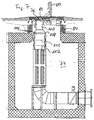
- Hollow ball 12 comprises, are arranged within the devices 14, via which the required Supply lines or connections are made available.
- the neck or extension 16 is in a concrete layer forming the surface 10 20 inset as cast.
- the hollow ball 12 is further connected on the bottom side to a concrete slab 22 which ensures that the hollow ball 12 cannot be raised.
- the concrete slab 12 is then positioned on a cleanliness layer 24.
- the ball 12 there is an unspecified guide or frame, along which a bracket 28 is slidable to connections originating from the bracket 28 how to move panel connector 30 such that they are above the surface 10 to connect with z.
- a bracket 28 is slidable to connections originating from the bracket 28 how to move panel connector 30 such that they are above the surface 10 to connect with z.
- an aircraft can be positioned or within the Hollow ball 12 are located.
- the bracket 28, the two vertically extending in the embodiment of FIGS. 1 and 2 Contains columns 29, 31, with a weight balance when lifting or lowering Counterweights 32 take place, which ensure that the bracket 38 with little force can be raised or lowered, is connected to a cover 34, thus forms with this one unit, which is aligned on the outside with the cover 18 of the neck 16 if necessary with the holder 28 lowered.
- cover 34 and Cover 18 form a unit.
- a connecting cable 38 is connected to the supply arrangement Provided, which are connected to an aircraft via the panel connector 30 can.
- a corresponding supply line is fed into the hollow sphere via a cable pipe 40, 42 12 introduced and first connected to junction boxes 44, 46, of which the cable 38 desired length leads to the panel connector 30.
- junction boxes 44, 46 of which the cable 38 desired length leads to the panel connector 30.
- the panel connector 30 becomes the cable 38 in more or less deposited on the grate 26 on a large scale.
- a connecting cable can also originate from the holder 28. To get involved to prevent the stored cable sections, they are separated from each other Areas placed on the grid 26. A partition 48 is used to separate the areas intended.
- the holder 28, which is mentioned in the exemplary embodiment, consists of two parallel to one another and interconnected columns 29, 31, damping springs 50 can be provided on the bottom side exhibit. In this respect, however, reference is made to well-known constructions.
- sewage pipe 52 which is a Check valve may contain.
- the waste water pipe 52 can be used in the hollow ball 12 run off accumulated water or be sucked off.
- the lid 34 has a handle on the outside in order to grasp it easily and thus together with the bracket 28 to the desired extent to be able to To be able to detect panel connector 30.
- the hollow ball 12 is surrounded by compressed ballast material 54. High static loads do not act on the hollow ball 12, because loads acting on the surface 10 are derived via the concrete layer 20.
- the hollow ball 12 may consist of polyester material and has in Middle area, ie in the area of line 56 a thickness of z. B. 8 mm. In the floor area the wall is stronger and can e.g. B. 20 mm.
- the weight of the Hollow ball 12 with a diameter of 200 cm is approximately 300 kg, provided that the hollow ball 12 is made of polyester.
- 1 and 2 is the underfloor supply arrangement according to the invention designed to provide electricity, so a corresponding construction also used to make a vehicle like air conditioned air supply. This will be illustrated with reference to FIG. 3, with the same elements same reference numerals are used.
- the hollow ball 12 is shown in the Drawings are not secured against buoyancy via a concrete slab 22. However, this should be preferably done.
- the holder 28 consisting of two columns 29, 31 can be seen, which are connected to the cover 34, in order in the manner previously described in the hollow sphere 12 existing and conditioned air-carrying hose 58 or a connection to be able to grasp this.
- the hose 58 can be folded in a zigzag fashion (section 60) when the cover 34 is aligned with the surface 10, that is to say the supply arrangement is closed.
- the hose 58 itself can be connected to a coupling 62 in the bottom region of the hollow ball 12 connecting pipe 64 are connected.
- FIG. 4 is intended to illustrate once again that the Bracket 28 with its columns 29, 31 or equivalent construction elements in guides 66, 68 runs, which are attached in the approach 16.
- the left part of the representation of the Fig. 4 indicates a raised position of the bracket 28, in which the bracket together with cover 34 protrudes above surface 10 of concrete layer 20.
- the right part gives that retracted position again, in which the cover 34 is aligned with the surface 10 becomes.
- the cover 34 has an opening in the cover 36 closes, which has an at least partially peripheral flange edge 70, which in is poured into the concrete layer 20, so that sufficient anchoring is ensured.
- the opening itself should be 600-700 mm in diameter.
- anchoring elements In order to connect the hollow ball 12 to the concrete slab 22, it is provided that on a horizontally extending ring anchoring elements penetrate the wall of the hollow ball 12.
- the corresponding anchoring elements such as bolts or screws point on the inside a head, between which and the inner wall of the hollow ball 12 a disc element runs to ensure a force distribution.
- a corresponding with the Anchoring elements such as hollow ball studs are then with their bottom area positioned in a formwork that is poured with concrete. After setting the Concrete is a connection between the hollow ball 12 and via the anchoring elements given the concrete slab 22.
- Anchoring elements can also be in the concrete slab 22 such as hooks or eyes 72 can be embedded in the unit concrete slab 22 hollow sphere 12 easily z. B. to be able to transport in a container.
- the bracket 28 and the supply line sections leading to it in a production facility in order to then carry out a final assembly on site.
- the hollow ball 12 with the concrete plate 22 in a corresponding Pit are used and then the connection to the supply pipes 40, 42nd on the one hand and between the supply lines supplied through the pipes 40, 42 the explosion-proof junction boxes 44, 46 on the other hand.
- the space around the hollow ball 12 is filled with ballast and compressed to then to pour the concrete layer 20.
- the concrete layer 20 can also be made of precast concrete slabs consist of a neck or neck 16 or cover 36 adapted Has recess, which is then shed to the required extent.
- the recordings either the Embodiments of FIGS. 3 to 4 correspondingly as a hollow ball or in the usual way can have a conventional manhole shape, ie a cylindrical or cuboid Geometry.
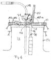
- an opening 76 is one generally designated by the reference numerals 74 provided recording via a first running parallel to the surface Axle 78, pivotable cover element 80, which is part of a cover 82, which covers the neck or neck 84 of the receptacle 74.
- the cover element 80 starts from one Bracket 86, which is penetrated by the first axis 78.
- the bracket 86 includes two in the longitudinal edge region of the cover element 80 extending lever elements 88, one of which first leg 90 has a U-shaped geometry and with cover element 80 connected is.
- a counterweight 96 which is independent of the position of the cover element 80 remains in the receptacle 74 or the neck-shaped extension 84.
- the U-shaped Geometry of the first leg 90 allows the first axis 78 to be outside
- the opening 76 runs so that it extends between the axis 78 and the opening 76
- Edge region 96 of the cover 92 is delimited by the U-shaped leg 90 Area 99 can extend with the cover element 80 open, as shown by FIG. 6 is made clear.
- the counterweight 94 is designed for the weight of the cover element such that the cover element 80 does not close completely. Thus, between the cover element 80 and object located at the edge of the opening 76 are not sheared off. In open Position in which the cover element 80 assumes a stable position is 5 and 6 of the angle ⁇ to more than 90 ° in accordance with the embodiment of FIGS.
- cover element 80 In order to meet safety regulations, 80 must be ensured when the cover element is open be that opening 76 is covered to an extent that is unintended or uncontrolled falling objects into the receptacle 74 or falling does not occur to a person.
- the cover element 80 a cover element 100 is assigned, which extends from the holder 86 and thus forms a rigid unit with the cover element 80.
- the cover element ends 80 spaced from the edge region 99 of the cover 82 which runs on the axis side, so that a free gap 102 results in the supply lines from the receptacle or the shaft 74 103 can be pulled out or introduced.
- Cover element 100 can be locked in the front edge area 102 via a pawl 104, which is retractable via a foot lever 106, namely when a controlled one Locking the cover element 80 in the cover 82 is desired.
- a cover element 100 corresponding to FIGS. 5 and 6 is assigned; because the opening 76 even when the cover element 80 is open, a supply hose 108 or a from this starting cylindrical approach 110, the z. B. with an airplane to supply this is connectable with conditioned air, closed.
- the hose points 108 annular or spiral inserts 111 are dimensioned and based on the length of the hose 108 is designed such that when in a tubular receptacle 112 of the deposited hose 100 with its upper edge region 114 or its cylindrical one Approach 110 extends to opening 76. So this is over the hose 108 closed. If the hose 108 is pulled out of the shaft 74, it is Opening 76 itself closed by the pulled hose 108.
- the approach 110 itself can be closed by a plate-shaped closure 112, which about z. B. a chain is connected to the cover element 80, so that when opening, that is Swiveling the cover element 80 about the axis 78 of the closure 112 with the Hose 108 is raised. Then it is only necessary that the closure 112 is detached from the hose 108 or the cylindrical extension 110.
- the connection between the closure 112 and the cylindrical projection 110 can by a kind Bayonet lock or by a screw cap.
- sliding elements such as rollers that extend at least along the edges along which the first axis 78 does not extend.
- the sliding elements can start from a frame-shaped second holder, which the first bracket 86 can be raised and due to gravity when closing the cover element 80 can be lowered.
Landscapes
- Engineering & Computer Science (AREA)
- Mechanical Engineering (AREA)
- Aviation & Aerospace Engineering (AREA)
- Environmental & Geological Engineering (AREA)
- Life Sciences & Earth Sciences (AREA)
- General Life Sciences & Earth Sciences (AREA)
- Mining & Mineral Resources (AREA)
- Paleontology (AREA)
- Civil Engineering (AREA)
- General Engineering & Computer Science (AREA)
- Structural Engineering (AREA)
- Feeding Of Articles To Conveyors (AREA)
- Sewage (AREA)
- Road Paving Structures (AREA)
Applications Claiming Priority (2)
| Application Number | Priority Date | Filing Date | Title |
|---|---|---|---|
| DE19941434 | 1999-08-30 | ||
| DE19941434A DE19941434A1 (de) | 1999-08-30 | 1999-08-30 | Versorgungsanordnung |
Publications (2)
| Publication Number | Publication Date |
|---|---|
| EP1081045A2 true EP1081045A2 (fr) | 2001-03-07 |
| EP1081045A3 EP1081045A3 (fr) | 2003-11-19 |
Family
ID=7920275
Family Applications (1)
| Application Number | Title | Priority Date | Filing Date |
|---|---|---|---|
| EP00117507A Withdrawn EP1081045A3 (fr) | 1999-08-30 | 2000-08-14 | Dispositif d'alimentation |
Country Status (2)
| Country | Link |
|---|---|
| EP (1) | EP1081045A3 (fr) |
| DE (1) | DE19941434A1 (fr) |
Cited By (3)
| Publication number | Priority date | Publication date | Assignee | Title |
|---|---|---|---|---|
| DE20209857U1 (de) * | 2002-06-25 | 2003-10-30 | Manfred Fladung GmbH, 63776 Mömbris | Verstauvorrichtung |
| ES2331983A1 (es) * | 2007-06-04 | 2010-01-21 | Bienvenido Peña Haro | Recogedor de mangueras de aire acondicionado. |
| CN115402528A (zh) * | 2022-08-09 | 2022-11-29 | 西安睿诺新能源有限公司 | 一种升降式加油系统 |
Families Citing this family (1)
| Publication number | Priority date | Publication date | Assignee | Title |
|---|---|---|---|---|
| FR2985389B1 (fr) * | 2012-01-03 | 2014-12-05 | Lefebure | Dispositif de raccordement a au moins un reseau de donnees, un reseau electrique et/ou un reseau fluidique, comprenant une borne de raccordement retractable |
Citations (8)
| Publication number | Priority date | Publication date | Assignee | Title |
|---|---|---|---|---|
| DE686834C (de) | 1936-06-09 | 1940-01-17 | Karl Wolter | - und Abfuellgeraeten |
| US2434824A (en) | 1946-06-20 | 1948-01-20 | Jr Albert E Watts | Gasoline dispensing system |
| GB674118A (en) | 1949-10-14 | 1952-06-18 | Albert Edward Watts Jr | Improvements in and relating to fuelling systems for aeroplanes |
| GB673998A (en) | 1949-10-14 | 1952-06-18 | Albert Edward Watts Jr | Improvements in and relating to fuelling and servicing systems for airplanes |
| DE8900046U1 (de) | 1989-01-04 | 1989-02-23 | Max Streicher KG, 8360 Deggendorf | Hydrantengehäuse |
| DE3743393C2 (fr) | 1987-09-05 | 1990-10-25 | Manfred Fladung Gmbh, 8752 Moembris, De | |
| DE9401022U1 (de) | 1994-01-24 | 1994-05-19 | Manfred Fladung GmbH, 63776 Mömbris | Versorgungsanordnung |
| US5535908A (en) | 1994-11-04 | 1996-07-16 | Sheu; Miin-Tsang | Receptacle combination for milk powder |
Family Cites Families (5)
| Publication number | Priority date | Publication date | Assignee | Title |
|---|---|---|---|---|
| CH527975A (de) * | 1970-08-04 | 1972-09-15 | Buchs Metallwerk Ag | Verfahren zum Erdeinbau von Tanks, insbesondere aus Kunststoff, und nach dem Verfahren eingebauter Tank |
| DE7318246U (de) * | 1973-05-15 | 1975-11-20 | Deutsche Geraetebau Gmbh | Unterirdisch versenkbare zapfanlage fuer brennkraftstoff zur betankung von fahrzeugen oder flugzeugen |
| US4467932A (en) * | 1983-10-03 | 1984-08-28 | Dabich Robert M | Easy lift pit lid |
| DE4038977A1 (de) * | 1990-12-06 | 1992-06-11 | Kloeckner Wilhelmsburger Gmbh | Doppelwandiger kugeltank fuer fluessigkeiten oder verfluessigte gase sowie verfahren zu seiner herstellung |
| DE19543524C1 (de) * | 1995-11-22 | 1997-03-13 | Horst Hammes | Anlage zum Sammeln und Verteilen von Regenwasser o. dgl. |
-
1999
- 1999-08-30 DE DE19941434A patent/DE19941434A1/de not_active Withdrawn
-
2000
- 2000-08-14 EP EP00117507A patent/EP1081045A3/fr not_active Withdrawn
Patent Citations (9)
| Publication number | Priority date | Publication date | Assignee | Title |
|---|---|---|---|---|
| DE686834C (de) | 1936-06-09 | 1940-01-17 | Karl Wolter | - und Abfuellgeraeten |
| US2434824A (en) | 1946-06-20 | 1948-01-20 | Jr Albert E Watts | Gasoline dispensing system |
| GB674118A (en) | 1949-10-14 | 1952-06-18 | Albert Edward Watts Jr | Improvements in and relating to fuelling systems for aeroplanes |
| GB673998A (en) | 1949-10-14 | 1952-06-18 | Albert Edward Watts Jr | Improvements in and relating to fuelling and servicing systems for airplanes |
| DE3743393C2 (fr) | 1987-09-05 | 1990-10-25 | Manfred Fladung Gmbh, 8752 Moembris, De | |
| DE8900046U1 (de) | 1989-01-04 | 1989-02-23 | Max Streicher KG, 8360 Deggendorf | Hydrantengehäuse |
| DE9401022U1 (de) | 1994-01-24 | 1994-05-19 | Manfred Fladung GmbH, 63776 Mömbris | Versorgungsanordnung |
| EP0664254A1 (fr) | 1994-01-24 | 1995-07-26 | Manfred Fladung GmbH | Dispositif d'alimentation |
| US5535908A (en) | 1994-11-04 | 1996-07-16 | Sheu; Miin-Tsang | Receptacle combination for milk powder |
Cited By (4)
| Publication number | Priority date | Publication date | Assignee | Title |
|---|---|---|---|---|
| DE20209857U1 (de) * | 2002-06-25 | 2003-10-30 | Manfred Fladung GmbH, 63776 Mömbris | Verstauvorrichtung |
| ES2331983A1 (es) * | 2007-06-04 | 2010-01-21 | Bienvenido Peña Haro | Recogedor de mangueras de aire acondicionado. |
| ES2331983B1 (es) * | 2007-06-04 | 2010-10-25 | Bienvenido Peña Haro | Recogedor de mangueras de aire acondicionado. |
| CN115402528A (zh) * | 2022-08-09 | 2022-11-29 | 西安睿诺新能源有限公司 | 一种升降式加油系统 |
Also Published As
| Publication number | Publication date |
|---|---|
| DE19941434A1 (de) | 2001-03-01 |
| EP1081045A3 (fr) | 2003-11-19 |
Similar Documents
| Publication | Publication Date | Title |
|---|---|---|
| DE3743393C2 (fr) | ||
| DE1634585A1 (de) | Auf Wasserflaechen aufstellbare Anlage | |
| EP3441527A1 (fr) | Dispositif de blocage destiné à empêcher la circulation des véhicules terrestres | |
| DE2603126A1 (de) | Arbeitskapsel zum einsatz bei die gesundheit bedrohenden umgebungsbedingungen | |
| EP1081045A2 (fr) | Dispositif d'alimentation | |
| EP2246502B1 (fr) | Elévateur doté d'une douille de réception adaptable | |
| EP0902129B1 (fr) | Procédé et dispositif d'installation des tuyaux dans le sol | |
| DE102009011464A1 (de) | Modulares Tragwerksystem aus schwimmenden Betonwaben | |
| CH423919A (de) | Unterirdische Kabine für elektrische Verteilanlagen | |
| DE2446508C3 (de) | Raumzelle aus Stahlbeton | |
| AT381751B (de) | Turmartiges stationsgebaeude fuer elektrische starkstromversorgungsanlagen | |
| DE69411598T2 (de) | Betankungsanlage | |
| DE1590601C (de) | Verfahren zum Anbringen von Kabelbrunnen od. dgl. in einer dazu vorgesehenen Grube in der Erde | |
| DE7820646U1 (de) | Raumzelle, insbesondere fertiggarage | |
| DE8806348U1 (de) | Verschalung für Baugruben | |
| EP1584757A2 (fr) | Dispositif de puit et arrangement de tuyauteries pour fluides | |
| DE2655032A1 (de) | Vorrichtung zum transport von raumzellen | |
| DE3703936A1 (de) | Ueberdachungskonstruktion fuer grossdeponien | |
| DE1949674U (de) | Vorrichtung zum manipulieren von raumgrossen bauwerken, insbesondere von fertiggaragen. | |
| DE1902014C (de) | Vorgefertigte Bauwerkszelle großen Formats aus Stahlbeton | |
| AT289358B (de) | Vorgefertigter Stahlbetonhohlkörper großen Formats mit aufrechtstehenden Seitenwänden und Verfahren zu dessen Herstellung, Transport und Aufstellung | |
| DE1684769B2 (de) | Gebaeude fuer eine transformatorstation, schaltstation o.dgl. | |
| DE20308637U1 (de) | Kabelschacht von im Erdboden verlegbaren Kabelrohren oder -schläuchen eines örtlichen Kabelrohr-Netzsystems | |
| DE2256658A1 (de) | Vorrichtung zum heben und senken von vorgefertigten, kastenfoermigen werkstuecken mit geschlossenem boden | |
| DE2803210A1 (de) | Tank zum versenken ins erdreich |
Legal Events
| Date | Code | Title | Description |
|---|---|---|---|
| PUAI | Public reference made under article 153(3) epc to a published international application that has entered the european phase |
Free format text: ORIGINAL CODE: 0009012 |
|
| AK | Designated contracting states |
Kind code of ref document: A2 Designated state(s): AT BE CH CY DE DK ES FI FR GB GR IE IT LI LU MC NL PT SE |
|
| AX | Request for extension of the european patent |
Free format text: AL;LT;LV;MK;RO;SI |
|
| PUAL | Search report despatched |
Free format text: ORIGINAL CODE: 0009013 |
|
| AK | Designated contracting states |
Kind code of ref document: A3 Designated state(s): AT BE CH CY DE DK ES FI FR GB GR IE IT LI LU MC NL PT SE |
|
| AX | Request for extension of the european patent |
Extension state: AL LT LV MK RO SI |
|
| AKX | Designation fees paid | ||
| REG | Reference to a national code |
Ref country code: DE Ref legal event code: 8566 |
|
| STAA | Information on the status of an ep patent application or granted ep patent |
Free format text: STATUS: THE APPLICATION IS DEEMED TO BE WITHDRAWN |
|
| 18D | Application deemed to be withdrawn |
Effective date: 20040520 |