EP1081064B1 - Bande transporteuse à espacement variable - Google Patents
Bande transporteuse à espacement variable Download PDFInfo
- Publication number
- EP1081064B1 EP1081064B1 EP99309074A EP99309074A EP1081064B1 EP 1081064 B1 EP1081064 B1 EP 1081064B1 EP 99309074 A EP99309074 A EP 99309074A EP 99309074 A EP99309074 A EP 99309074A EP 1081064 B1 EP1081064 B1 EP 1081064B1
- Authority
- EP
- European Patent Office
- Prior art keywords
- linking portions
- linking
- conveyor belt
- wide
- narrow
- Prior art date
- Legal status (The legal status is an assumption and is not a legal conclusion. Google has not performed a legal analysis and makes no representation as to the accuracy of the status listed.)
- Expired - Lifetime
Links
- 239000000463 material Substances 0.000 description 9
- 238000010276 construction Methods 0.000 description 2
- RLLPVAHGXHCWKJ-IEBWSBKVSA-N (3-phenoxyphenyl)methyl (1s,3s)-3-(2,2-dichloroethenyl)-2,2-dimethylcyclopropane-1-carboxylate Chemical compound CC1(C)[C@H](C=C(Cl)Cl)[C@@H]1C(=O)OCC1=CC=CC(OC=2C=CC=CC=2)=C1 RLLPVAHGXHCWKJ-IEBWSBKVSA-N 0.000 description 1
- 239000011248 coating agent Substances 0.000 description 1
- 238000000576 coating method Methods 0.000 description 1
- 238000010411 cooking Methods 0.000 description 1
- 238000001816 cooling Methods 0.000 description 1
- 230000003247 decreasing effect Effects 0.000 description 1
- 230000001419 dependent effect Effects 0.000 description 1
- 238000001035 drying Methods 0.000 description 1
- 238000009434 installation Methods 0.000 description 1
- 238000012423 maintenance Methods 0.000 description 1
- 238000004519 manufacturing process Methods 0.000 description 1
- 239000002184 metal Substances 0.000 description 1
- 239000007769 metal material Substances 0.000 description 1
- 238000012986 modification Methods 0.000 description 1
- 230000004048 modification Effects 0.000 description 1
- 229910052755 nonmetal Inorganic materials 0.000 description 1
- 229910001220 stainless steel Inorganic materials 0.000 description 1
- 239000010935 stainless steel Substances 0.000 description 1
- 238000006467 substitution reaction Methods 0.000 description 1
- 238000003466 welding Methods 0.000 description 1
Images

Classifications
-
- B—PERFORMING OPERATIONS; TRANSPORTING
- B65—CONVEYING; PACKING; STORING; HANDLING THIN OR FILAMENTARY MATERIAL
- B65G—TRANSPORT OR STORAGE DEVICES, e.g. CONVEYORS FOR LOADING OR TIPPING, SHOP CONVEYOR SYSTEMS OR PNEUMATIC TUBE CONVEYORS
- B65G17/00—Conveyors having an endless traction element, e.g. a chain, transmitting movement to a continuous or substantially-continuous load-carrying surface or to a series of individual load-carriers; Endless-chain conveyors in which the chains form the load-carrying surface
- B65G17/06—Conveyors having an endless traction element, e.g. a chain, transmitting movement to a continuous or substantially-continuous load-carrying surface or to a series of individual load-carriers; Endless-chain conveyors in which the chains form the load-carrying surface having a load-carrying surface formed by a series of interconnected, e.g. longitudinal, links, plates, or platforms
- B65G17/08—Conveyors having an endless traction element, e.g. a chain, transmitting movement to a continuous or substantially-continuous load-carrying surface or to a series of individual load-carriers; Endless-chain conveyors in which the chains form the load-carrying surface having a load-carrying surface formed by a series of interconnected, e.g. longitudinal, links, plates, or platforms the surface being formed by the traction element
-
- B—PERFORMING OPERATIONS; TRANSPORTING
- B65—CONVEYING; PACKING; STORING; HANDLING THIN OR FILAMENTARY MATERIAL
- B65G—TRANSPORT OR STORAGE DEVICES, e.g. CONVEYORS FOR LOADING OR TIPPING, SHOP CONVEYOR SYSTEMS OR PNEUMATIC TUBE CONVEYORS
- B65G15/00—Conveyors having endless load-conveying surfaces, i.e. belts and like continuous members, to which tractive effort is transmitted by means other than endless driving elements of similar configuration
- B65G15/30—Belts or like endless load-carriers
- B65G15/54—Endless load-carriers made of interwoven ropes or wires
-
- B—PERFORMING OPERATIONS; TRANSPORTING
- B65—CONVEYING; PACKING; STORING; HANDLING THIN OR FILAMENTARY MATERIAL
- B65G—TRANSPORT OR STORAGE DEVICES, e.g. CONVEYORS FOR LOADING OR TIPPING, SHOP CONVEYOR SYSTEMS OR PNEUMATIC TUBE CONVEYORS
- B65G17/00—Conveyors having an endless traction element, e.g. a chain, transmitting movement to a continuous or substantially-continuous load-carrying surface or to a series of individual load-carriers; Endless-chain conveyors in which the chains form the load-carrying surface
- B65G17/06—Conveyors having an endless traction element, e.g. a chain, transmitting movement to a continuous or substantially-continuous load-carrying surface or to a series of individual load-carriers; Endless-chain conveyors in which the chains form the load-carrying surface having a load-carrying surface formed by a series of interconnected, e.g. longitudinal, links, plates, or platforms
- B65G17/063—Conveyors having an endless traction element, e.g. a chain, transmitting movement to a continuous or substantially-continuous load-carrying surface or to a series of individual load-carriers; Endless-chain conveyors in which the chains form the load-carrying surface having a load-carrying surface formed by a series of interconnected, e.g. longitudinal, links, plates, or platforms the load carrying surface being formed by profiles, rods, bars, rollers or the like attached to more than one traction element
- B65G17/064—Conveyors having an endless traction element, e.g. a chain, transmitting movement to a continuous or substantially-continuous load-carrying surface or to a series of individual load-carriers; Endless-chain conveyors in which the chains form the load-carrying surface having a load-carrying surface formed by a series of interconnected, e.g. longitudinal, links, plates, or platforms the load carrying surface being formed by profiles, rods, bars, rollers or the like attached to more than one traction element the profiles, rods, bars, rollers or the like being interconnected by a mesh or grid-like structure
-
- B—PERFORMING OPERATIONS; TRANSPORTING
- B65—CONVEYING; PACKING; STORING; HANDLING THIN OR FILAMENTARY MATERIAL
- B65G—TRANSPORT OR STORAGE DEVICES, e.g. CONVEYORS FOR LOADING OR TIPPING, SHOP CONVEYOR SYSTEMS OR PNEUMATIC TUBE CONVEYORS
- B65G2201/00—Indexing codes relating to handling devices, e.g. conveyors, characterised by the type of product or load being conveyed or handled
- B65G2201/02—Articles
Definitions
- the present invention relates to conveyor belts and in particular, to a conveyor belt, such as a flat wire belt or balanced weave belt, having conveyor belt links with alternating wide and narrow regions.
- Conveyor belts are commonly used for conveying articles during cooling, drying, coating, cooking and many other applications.
- Examples of conveyor belts used for such applications include wire mesh belts, flat or ribbon wire belts (also referred to as honeycomb belts), and balanced weave belts.
- One example of a flat wire belt is disclosed in U.S. Patent No. 5,501,319, incorporated herein by reference.
- One example of a balanced weave belt is disclosed in U.S. Patent No. 5,375,695, incorporated herein by reference.
- Each of these belts are advantageous, for food processing in particular, because they provide flexibility, an open, flow-through construction, a sanitary construction, simple installation and maintenance, and the ability to be positively driven.
- German Patent No. DE 15 31 060 discloses a wire belt having a wide link section with a narrow link section on the ends thereof.
- the first and the second narrow pitch sections are designed to improve the only strength of the belt in the areas along the edges of the conveyor belt.
- drive sprockets can only engage the belt along the middle of the belt in the wide link section. As a result, an uneven force distribution is created along the width of the belt that increases the load at the outside edges of the belt.
- the uneven force distribution can lead to the edges curling in two dimensions (i.e., the first dimension of induced curl is in the same plane as the belt where the edges lag behind the center of the belt and the second dimension is for the edges of the belt to curl vertically above the conveying surface), thus creating a conveying surface that is not flat.
- the overall strength of the belt cannot be increased without increasing belt's weight or without creating excessively large spaces between the links.
- Conveyor belt manufacturers have always searched for ways to reduce the amount of material and time needed to manufacture these conveyor belts as well as to reduce the weight. Prior attempts at reducing weight and material, however, have resulted in a significant decrease in belt strength. Reducing belt material can also result in larger spaces through the belt that allow smaller articles to fall through.
- a conveyor belt as specified in claim 1.
- Another aspect of the invention provides a flat wire link for use in a conveyor belt, as specified in claim 9.
- Preferred aspects of the invention are specified in the dependent claims.
- the present invention features a conveyor belt.
- the conveyor belt includes a plurality of links each of which is linked with at least one adjacent wire link in the conveyor belt.
- Each link includes a first end and a second end and a plurality of linking portions between the first end and the second end.
- the plurality of linking portions are linked with respective linking portions in an adjacent link.
- the plurality of linking portions include alternating narrow linking portions and wide linking portions that alternate from proximate the first end to proximate the second end of each of the links.
- the wide linking portions have a width greater than the width of the narrow linking portions.
- the narrow linking portions and wide linking portions are linked with respective narrow linking portions and wide linking portions in the adjacent wire link forming narrow spaces and wide spaces. Alternating the wide linking portions and narrow linking portions reduces the amount of material needed for the conveyor belt.
- Each link preferably includes an odd number of linking portions where the number of wide linking portions equals the number of narrow linking portions minus one.
- Each of the plurality of links preferably has first and second of the narrow linking portions located at the first and second ends of the links.
- the width of the narrow linking portions is preferably dimensioned to receive a sprocket, for driving the conveyor belt.
- the present invention features a flat wire conveyor belt.
- the flat wire conveyor belt comprises a plurality of flat wire links.
- Each of the flat wire links comprises a first end and a second end, and a plurality of linking portions between the first end and the second end.
- the linking portions include alternating wide linking portions and narrow linking portions that alternate from proximate the first end to proximate the second end of each of the wire links.
- Each of the linking portions also have an aperture extending therethrough.
- a linking rod extends through the aperture in each of the linking portions to link each of the flat wire links to adjacent flat wire links.
- the linking rod is secured at first and second rod ends to edges of the belt, for example, by welding or clinching.
- the conveyer belt is a balanced weave belt having wire links woven around linking bars.
- the present invention also features a flat wire link for use in a flat wire conveyor belt.
- the flat wire link includes a first end and a second end, and a plurality of linking portions between the first end and the second end.
- Each of the plurality of linking portions includes apertures for receiving a linking rod for linking the linking portions to adjacent flat wire links in the conveyor belt.
- At least some of the linking portions include alternating wide linking portions and narrow linking portions. The wide linking portions having a width greater than a width of the narrow linking portions.
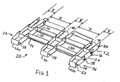
- the flat wire conveyor belt 20 also includes linking rods 34 extending through apertures 28 in the linking portions 30, 32, thereby linking the flat wire links 22 to adjacent flat wire links 22.
- the ends of the linking rods 34 are secured to the respective ends 24, 26 of the flat wire links 22, for example with a welded button head 36 or with a clinched end 38.
- the plurality of flat wire links 22 are preferably linked with linking rods 34 to form an endless flat wire conveyor belt.
- each flat wire link 22 preferably form an undulating shape. Although a modified square sine wave shape is shown in the exemplary embodiment, other shapes are contemplated.
- the flat wire links 22 can be made of stainless steel or any other suitable metal or non-metal material.
- the wide linking portions 30 have a width X that is greater than the width Y of the narrow linking portions 32.
- the larger space or width X is variable and can depend on the size of the articles to be conveyed.
- the narrower space or width Y is preferably dimensioned to receive drive sprockets 40 used to drive the conveyor belt 20.
- the flat wire conveyor belt 20 is formed by essentially dropping or eliminating every other picket from a conventional flat wire conveyor belt.
- the larger width X is preferably at least about twice the narrower width Y to effectively reduce the material used and the weight of the belt 20.
- the conveyor belt 20 preferably includes narrow linking portions 32a, 32b proximate the first and second ends 24, 26 of the flat wire links 22, to drive the conveyor belt 20 with sprockets 40 close to the first and second ends 24, 26 of the wire links 22.
- Driving the conveyer belt 20 with sprockets 40 positioned in narrow linking portions 32a, 32b at the ends 24, 26 reduces the chance of belt failure caused by stress imposed by the drive sprockets 40.
- the conveyor belt can have wide linking portions proximate first and second ends 24, 26.
- each wide linking portion 30 having substantially the same width X and each narrow linking portion 32 having substantially the same width Y .
- the present invention contemplates wide linking portions 30 of varying widths and narrow linking portions 32 of varying widths, provided that the alternating wide linking portions 30 and narrow linking portions 32 match with respective wide linking portions 30 and narrow linking portions 32 of adjacent wire links 22.
- the preferred embodiment includes wide linking portions 30 and narrow linking portions 32 that alternate along the entire width of each flat wire link 22 from the first end 24 to the second end 26.
- the number of wide linking portions 30 is equal to the number of narrow linking portions 32 minus one.
- the wide linking portions 30 and narrow linking portions 32 can alternate along only one or more portions of each flat wire link 22 with the remaining linking portions being of the same width.
- a balanced weave belt 50 includes a plurality of wire links 52 woven around linking rods 54.
- the wire links 52 are woven to form alternating wide and narrow linking portions 56, 58 along at least a portion of the balanced weave belt 50.
- the wide and narrow linking portions 56, 58 are shown as having a consistent wide and narrow spacing, varying wide and narrow spacings are also contemplated.
- Another variation of the balanced weave belt 60 is shown in FIG. 3.
- the balanced weave belt 50, 60 essentially eliminates every other weave in conventional balanced weave belts 50, 60, thereby eliminating material.
- FIG. 1 shows a flat wire belt (FIG. 1) and a balanced weave belt (FIGS. 2 and 3), the concept of alternating wide and narrow linking portions or eliminating linking portions can be used with any type of conveyor belts.
- a conveyor belt can be formed with less material, in less time, and having a lower weight. Depending upon the materials used, this lighter conveyor belt can be made without reducing the belt strength.
Landscapes
- Engineering & Computer Science (AREA)
- Mechanical Engineering (AREA)
- Textile Engineering (AREA)
- Belt Conveyors (AREA)
Claims (10)
- Bande transporteuse (20,50,60) comprenant une pluralité de tiges de liaison (34,54), et une pluralité de liaisons (22,52) liées à ladite pluralité de tiges de liaison (34,54), dans laquelle les liaisons adjacentes (22,52) dans ladite bande transporteuse sont liées à l'une desdites tiges de liaison (34,54), chacune de ladite pluralité de liaisons (22,52) ayant une pluralité de portions de liaisons (30, 32,56,58) entre une première extrémité (24) et une seconde extrémité (26) et dans laquelle,
ladite pluralité de portions de liaison (30,32,56,58) comprend en alternance des portions de liaison larges (30,56) et des portions de liaison étroites (32,58), dans laquelle lesdites portions de liaison étroites (32,58) et les portions de liaison larges (30,56) alternent de ladite première extrémité (24) à ladite seconde extrémité (26) de chaque dite pluralité de liaisons (22,52), lesdites portions de liaison larges (30,56) ayant une largeur (x) supérieure à la largeur (y) desdites portions de liaison étroites (32,58) et les portions de liaison adjacentes ayant des largeurs en alternance. - Bande transporteuse (20,50,60) de la revendication 1, dans laquelle lesdites liaisons (22,52) sont des fils (52) tissés autour desdites tiges de liaison (54).
- Bande transporteuse (20,50,60) selon la revendication 1, dans laquelle lesdites liaisons (22,52) sont des liaisons de fils plats (22), dans laquelle lesdites tiges de liaison (34) s'étendent à travers des ouvertures (28) dans lesdites portions de liaison (30,32) desdites liaisons de fils plats (22), et chacune desdites tiges de liaison (34) comprenant des première et seconde extrémités fixées sur des bords de ladite bande.
- Bande transporteuse (20,50,60) selon la revendication 3, dans laquelle lesdites première et seconde extrémités desdites tiges de liaison (34) comprennent des têtes rondes (36) soudées sur lesdits bords de ladite bande.
- Bande transporteuse (20,50,60) selon la revendication 3, dans laquelle lesdites première et seconde extrémités desdites tiges de liaison (34) sont rivéesau niveau desdites extrémités de ladite bande.
- Bande transporteuse (20,50,60) selon la revendication 3, dans laquelle lesdites portions de liaison larges (30,56) sont au moins égales à environ deux fois la largeur desdites portions de liaison étroites (32,58).
- Bande transporteuse (20,50,60) selon la revendication 1, dans laquelle chacune de ladite pluralité de liaisons (22,52) comprend de plus un nombre impair de ladite pluralité de portions de liaison (30,32,56,58), et dans laquelle un certain nombre desdites portions de liaison larges (30,56) est égal au nombre desdites portions de liaison étroites (32,58) moins un.
- Bande transporteuse (20,50,60) selon la revendication 1, dans laquelle chacune de ladite pluralité de liaisons (22,52) comporte des première et seconde desdites portions de liaisons étroites (32,58) situées au niveau des première et seconde extrémités (24,26) desdites liaisons (22,52).
- Liaison de fils plats (22) pour utilisation dans une bande transporteuse (20), ladite liaison de fils plats (22) comprenant :une première extrémité (24) et une seconde extrémité (26) ; etune pluralité de portions de liaison (30,32) entre ladite première extrémité (24) et ladite seconde extrémité (26), chacune de ladite pluralité de portions de liaison (30,32) comprenant des ouvertures (28) pour recevoir une tige de liaison (34) pour relier lesdites portions de liaison (30,32) à des liaisons de fils plats adjacentes (22) dans ladite bande transporteuse (20), ladite pluralité de portions de liaison (30,32) étant en alternance des portions de liaison larges (30) et des portions de liaison étroites (32), lesdites portions de liaison larges (30) ayant une largeur (X) supérieure à une largeur (y) desdites portions de liaison étroites (22) et les portions de liaison adjacentes ont des largeurs en alternance.
- Liaison de fils plats (22) selon la revendication 9, dans laquelle chacune desdites portions de liaison larges (30) ont sensiblement la même largeur, et dans laquelle chacune desdites portions de liaison étroites (32) possède sensiblement la même largeur, et dans laquelle lesdites portions de liaison larges (30) sont au moins approximativement deux fois aussi larges que lesdites portions de liaison étroites (32).
Applications Claiming Priority (2)
| Application Number | Priority Date | Filing Date | Title |
|---|---|---|---|
| US09/371,139 US6202833B1 (en) | 1997-02-20 | 1999-08-09 | Conveyor belt with variable spacing |
| US371139 | 1999-08-09 |
Publications (3)
| Publication Number | Publication Date |
|---|---|
| EP1081064A2 EP1081064A2 (fr) | 2001-03-07 |
| EP1081064A3 EP1081064A3 (fr) | 2001-12-05 |
| EP1081064B1 true EP1081064B1 (fr) | 2005-01-19 |
Family
ID=23462644
Family Applications (1)
| Application Number | Title | Priority Date | Filing Date |
|---|---|---|---|
| EP99309074A Expired - Lifetime EP1081064B1 (fr) | 1999-08-09 | 1999-11-15 | Bande transporteuse à espacement variable |
Country Status (3)
| Country | Link |
|---|---|
| US (1) | US6202833B1 (fr) |
| EP (1) | EP1081064B1 (fr) |
| DE (1) | DE69923306T2 (fr) |
Families Citing this family (15)
| Publication number | Priority date | Publication date | Assignee | Title |
|---|---|---|---|---|
| US6854590B2 (en) | 2001-07-24 | 2005-02-15 | Fmc Technologies, Inc. | Conveyor belt assembly |
| ATE523452T1 (de) * | 2005-09-30 | 2011-09-15 | Cambridge Int Inc | Drahtförderband mit spannungsübertragung |
| PL2200913T3 (pl) * | 2007-09-21 | 2015-05-29 | Cambridge Int Inc | System z płaskim drucianym pasem przenośnika |
| PL2220396T3 (pl) * | 2007-12-03 | 2015-11-30 | Cambridge Int Inc | System szybkiego łączenia taśmy przenośnikowej i sposób do niego |
| US8739966B2 (en) | 2011-09-20 | 2014-06-03 | Wire Belt Company Of America | Flat wire conveyor belt with multiple connecting rods and strengthening edges |
| USD695985S1 (en) * | 2011-12-30 | 2013-12-17 | Cambridge International Inc. | Mesh panel |
| US8844713B2 (en) | 2012-03-06 | 2014-09-30 | Ashworth Bros., Inc. | Conveyor belt link with wear resistance features |
| USD712158S1 (en) | 2013-09-17 | 2014-09-02 | Cambridge International Inc. | Mesh panel |
| ES2742426T3 (es) * | 2013-11-08 | 2020-02-14 | Cambridge Int Inc | Cinta transportadora de espaciado variable con los extremos de las varillas curvados |
| US9169074B2 (en) * | 2013-11-27 | 2015-10-27 | Cambridge International, Inc. | Variable width drive openings for conveyor belt |
| USD719359S1 (en) * | 2014-01-24 | 2014-12-16 | Cambridge International, Inc. | Mesh panel |
| USD739110S1 (en) | 2014-06-09 | 2015-09-15 | Cambridge International Inc. | Mesh panel |
| US10507978B2 (en) | 2017-10-28 | 2019-12-17 | Rabbit Designs LLC | Radius and variable width conveyor belt |
| CN112375893B (zh) * | 2020-11-04 | 2024-11-26 | 杭州和源精密工具有限公司 | 档条一体式锯片淬火提升网带 |
| US12459743B2 (en) | 2022-09-13 | 2025-11-04 | Cambridge International, Inc. | Weldless conveyor belt systems and methods |
Family Cites Families (12)
| Publication number | Priority date | Publication date | Assignee | Title |
|---|---|---|---|---|
| US2862602A (en) | 1955-10-28 | 1958-12-02 | Wire Belt Company Of America I | Wire belt |
| DE1531060A1 (de) * | 1967-05-23 | 1969-08-07 | Steinhaus Gmbh | Drahtgurt mit verstaerkten Laengskanten |
| US4078655A (en) * | 1977-02-25 | 1978-03-14 | Ashworth Bros., Inc. | Small radius conveyor belt and conveying system |
| EP0038461B1 (fr) * | 1980-04-21 | 1984-11-28 | Draadindustrie Jonge Poerink B.V. | Couroie de transport en treillis de fil métallique et procédé pour la fabrication de cette courroie |
| US4846339A (en) * | 1987-03-11 | 1989-07-11 | Ashworth Bros., Inc. | Flat wire conveyor with differential pitch |
| US4754871A (en) | 1987-10-05 | 1988-07-05 | Wire Belt Company Of America | Wire mesh belt and splicer |
| DE4031212A1 (de) | 1990-10-04 | 1992-04-09 | Kufferath Geb Gkd | Drahtgewebeband |
| DE4122805C1 (de) | 1991-07-10 | 1994-10-06 | Heimbach Gmbh Thomas Josef | Drahtgliederband |
| US5375695A (en) | 1993-05-05 | 1994-12-27 | Maryland Wire Belts, Inc. | Curved-path woven-wire belt and conveyance methods and apparatus |
| US5404998A (en) * | 1994-01-03 | 1995-04-11 | Wire Belt Company Of America | Wire conveyor belt with closed edges and method of making same |
| US5501319A (en) | 1994-06-21 | 1996-03-26 | Ashworth Bros., Inc. | Conveyor belt with asymmetric edge links |
| US5950807A (en) * | 1997-02-20 | 1999-09-14 | Wire Belt Company Of America | Wire belt with variable spacing and method of making |
-
1999
- 1999-08-09 US US09/371,139 patent/US6202833B1/en not_active Expired - Lifetime
- 1999-11-15 EP EP99309074A patent/EP1081064B1/fr not_active Expired - Lifetime
- 1999-11-15 DE DE69923306T patent/DE69923306T2/de not_active Expired - Lifetime
Also Published As
| Publication number | Publication date |
|---|---|
| EP1081064A3 (fr) | 2001-12-05 |
| EP1081064A2 (fr) | 2001-03-07 |
| US6202833B1 (en) | 2001-03-20 |
| DE69923306D1 (de) | 2005-02-24 |
| DE69923306T2 (de) | 2006-04-06 |
Similar Documents
| Publication | Publication Date | Title |
|---|---|---|
| EP1081064B1 (fr) | Bande transporteuse à espacement variable | |
| EP2200913B1 (fr) | Système de courroie transporteuse à fil plat | |
| EP2871144B1 (fr) | Courroies de transport à espacement variable avec des extrémités de tige de sertissage | |
| US8985318B2 (en) | Conveyor belt with composite link | |
| EP1009688B1 (fr) | Bande transporteuse presentant un espacement variable et procede de fabrication | |
| US20060163039A1 (en) | Plastic woven spiral conveyor belt | |
| EP1223119B1 (fr) | Convoyeur en fil métallique tissé dont les mailles ont une forme composée | |
| US6129205A (en) | Variable loop count conveyor belt | |
| EP1270454A1 (fr) | Module d'une bande transporteuse avec grille lisse | |
| CA2295033A1 (fr) | Bande transporteuse maillee metallique | |
| US2912098A (en) | Belt conveyor | |
| US20250388407A1 (en) | Wear-resistant wire-mesh metal-belt conveyors | |
| JP7701690B2 (ja) | メッシュベルト | |
| US7278534B2 (en) | Compact-grid conveyor belt | |
| US20030075418A1 (en) | Self-stacking conveyor belt and method | |
| GB2322386A (en) | Fencing nets with varying strength | |
| EP4436901A1 (fr) | Bande transporteuse modulaire à liaison oblique | |
| GB2347882A (en) | Grading screen |
Legal Events
| Date | Code | Title | Description |
|---|---|---|---|
| PUAI | Public reference made under article 153(3) epc to a published international application that has entered the european phase |
Free format text: ORIGINAL CODE: 0009012 |
|
| AK | Designated contracting states |
Kind code of ref document: A2 Designated state(s): AT BE CH CY DE DK ES FI FR GB GR IE IT LI LU MC NL PT SE Kind code of ref document: A2 Designated state(s): DE GB IT NL |
|
| AX | Request for extension of the european patent |
Free format text: AL;LT;LV;MK;RO;SI |
|
| PUAL | Search report despatched |
Free format text: ORIGINAL CODE: 0009013 |
|
| AK | Designated contracting states |
Kind code of ref document: A3 Designated state(s): AT BE CH CY DE DK ES FI FR GB GR IE IT LI LU MC NL PT SE |
|
| AX | Request for extension of the european patent |
Free format text: AL;LT;LV;MK;RO;SI |
|
| 17P | Request for examination filed |
Effective date: 20020530 |
|
| AKX | Designation fees paid |
Free format text: DE GB IT NL |
|
| 17Q | First examination report despatched |
Effective date: 20030714 |
|
| GRAP | Despatch of communication of intention to grant a patent |
Free format text: ORIGINAL CODE: EPIDOSNIGR1 |
|
| GRAS | Grant fee paid |
Free format text: ORIGINAL CODE: EPIDOSNIGR3 |
|
| GRAA | (expected) grant |
Free format text: ORIGINAL CODE: 0009210 |
|
| AK | Designated contracting states |
Kind code of ref document: B1 Designated state(s): DE GB IT NL |
|
| PG25 | Lapsed in a contracting state [announced via postgrant information from national office to epo] |
Ref country code: NL Free format text: LAPSE BECAUSE OF FAILURE TO SUBMIT A TRANSLATION OF THE DESCRIPTION OR TO PAY THE FEE WITHIN THE PRESCRIBED TIME-LIMIT Effective date: 20050119 Ref country code: IT Free format text: LAPSE BECAUSE OF FAILURE TO SUBMIT A TRANSLATION OF THE DESCRIPTION OR TO PAY THE FEE WITHIN THE PRESCRIBED TIME-LIMIT;WARNING: LAPSES OF ITALIAN PATENTS WITH EFFECTIVE DATE BEFORE 2007 MAY HAVE OCCURRED AT ANY TIME BEFORE 2007. THE CORRECT EFFECTIVE DATE MAY BE DIFFERENT FROM THE ONE RECORDED. Effective date: 20050119 |
|
| REG | Reference to a national code |
Ref country code: GB Ref legal event code: FG4D |
|
| REG | Reference to a national code |
Ref country code: IE Ref legal event code: FG4D |
|
| REF | Corresponds to: |
Ref document number: 69923306 Country of ref document: DE Date of ref document: 20050224 Kind code of ref document: P |
|
| NLV1 | Nl: lapsed or annulled due to failure to fulfill the requirements of art. 29p and 29m of the patents act | ||
| PLBE | No opposition filed within time limit |
Free format text: ORIGINAL CODE: 0009261 |
|
| STAA | Information on the status of an ep patent application or granted ep patent |
Free format text: STATUS: NO OPPOSITION FILED WITHIN TIME LIMIT |
|
| 26N | No opposition filed |
Effective date: 20051020 |
|
| PGFP | Annual fee paid to national office [announced via postgrant information from national office to epo] |
Ref country code: DE Payment date: 20181128 Year of fee payment: 20 |
|
| PGFP | Annual fee paid to national office [announced via postgrant information from national office to epo] |
Ref country code: GB Payment date: 20181127 Year of fee payment: 20 |
|
| REG | Reference to a national code |
Ref country code: DE Ref legal event code: R071 Ref document number: 69923306 Country of ref document: DE |
|
| REG | Reference to a national code |
Ref country code: GB Ref legal event code: PE20 Expiry date: 20191114 |
|
| PG25 | Lapsed in a contracting state [announced via postgrant information from national office to epo] |
Ref country code: GB Free format text: LAPSE BECAUSE OF EXPIRATION OF PROTECTION Effective date: 20191114 |