EP1081081A2 - Traversiervorrichtung mit rotierenden Flügeln - Google Patents
Traversiervorrichtung mit rotierenden Flügeln Download PDFInfo
- Publication number
- EP1081081A2 EP1081081A2 EP00117550A EP00117550A EP1081081A2 EP 1081081 A2 EP1081081 A2 EP 1081081A2 EP 00117550 A EP00117550 A EP 00117550A EP 00117550 A EP00117550 A EP 00117550A EP 1081081 A2 EP1081081 A2 EP 1081081A2
- Authority
- EP
- European Patent Office
- Prior art keywords
- traverse
- yarn
- wing
- wings
- rotary
- Prior art date
- Legal status (The legal status is an assumption and is not a legal conclusion. Google has not performed a legal analysis and makes no representation as to the accuracy of the status listed.)
- Withdrawn
Links
- 230000007246 mechanism Effects 0.000 description 18
- 238000004804 winding Methods 0.000 description 11
- 238000006243 chemical reaction Methods 0.000 description 10
- 230000005540 biological transmission Effects 0.000 description 9
- 230000015572 biosynthetic process Effects 0.000 description 4
- 238000010586 diagram Methods 0.000 description 4
- 230000008859 change Effects 0.000 description 2
- 230000003247 decreasing effect Effects 0.000 description 2
- 230000008878 coupling Effects 0.000 description 1
- 238000010168 coupling process Methods 0.000 description 1
- 238000005859 coupling reaction Methods 0.000 description 1
- 230000007423 decrease Effects 0.000 description 1
- 230000000694 effects Effects 0.000 description 1
- 238000000034 method Methods 0.000 description 1
- 230000008569 process Effects 0.000 description 1
- 238000007493 shaping process Methods 0.000 description 1
Images





Classifications
-
- B—PERFORMING OPERATIONS; TRANSPORTING
- B65—CONVEYING; PACKING; STORING; HANDLING THIN OR FILAMENTARY MATERIAL
- B65H—HANDLING THIN OR FILAMENTARY MATERIAL, e.g. SHEETS, WEBS, CABLES
- B65H54/00—Winding, coiling, or depositing filamentary material
- B65H54/02—Winding and traversing material on to reels, bobbins, tubes, or like package cores or formers
- B65H54/28—Traversing devices; Package-shaping arrangements
- B65H54/2836—Traversing devices; Package-shaping arrangements with a rotating guide for traversing the yarn
- B65H54/2839—Traversing devices; Package-shaping arrangements with a rotating guide for traversing the yarn counter rotating guides, e.g. wings
-
- B—PERFORMING OPERATIONS; TRANSPORTING
- B65—CONVEYING; PACKING; STORING; HANDLING THIN OR FILAMENTARY MATERIAL
- B65H—HANDLING THIN OR FILAMENTARY MATERIAL, e.g. SHEETS, WEBS, CABLES
- B65H54/00—Winding, coiling, or depositing filamentary material
- B65H54/02—Winding and traversing material on to reels, bobbins, tubes, or like package cores or formers
- B65H54/28—Traversing devices; Package-shaping arrangements
- B65H54/32—Traversing devices; Package-shaping arrangements with thread guides reciprocating or oscillating with variable stroke
- B65H54/325—Traversing devices; Package-shaping arrangements with thread guides reciprocating or oscillating with variable stroke in accordance with growth of the package
-
- B—PERFORMING OPERATIONS; TRANSPORTING
- B65—CONVEYING; PACKING; STORING; HANDLING THIN OR FILAMENTARY MATERIAL
- B65H—HANDLING THIN OR FILAMENTARY MATERIAL, e.g. SHEETS, WEBS, CABLES
- B65H2701/00—Handled material; Storage means
- B65H2701/30—Handled filamentary material
- B65H2701/31—Textiles threads or artificial strands of filaments
Definitions
- the present invention relates to a wing traverse apparatus (also known as a “rotary traverse apparatus”) that traverses a yarn by transferring it between a set of opposedly rotating traverse wings.
- a wing traverse apparatus also known as a "rotary traverse apparatus” that traverses a yarn by transferring it between a set of opposedly rotating traverse wings.
- a conventional wing traverse apparatus provided with traverse guides that form a traverse track in which the yarn wound into a package is traversed, and with a set of opposedly rotating traverse wings that transfer the yarn therebetween at yarn transfer points defining lateral ends of the traverse track, is known.
- Such a traverse apparatus traverses the yarn by transferring it between the traverse wings at the yarn transfer points.
- This traverse apparatus is arranged such that the rotary track of the traverse wings and the traverse tracks of the traverse guides set a fixed traverse width between the yarn transfer points. Consequently, it is very difficult to change the traverse width to perform "creeping" or to form packages with tapered ends.
- the present invention discloses a wing traverse apparatus having a traverse guide that defines a traverse track for a yarn, and a set of traverse wings that rotate in opposite directions and which transfer the yarn at yarn transfer points defining lateral ends of the traverse track, the apparatus characterized in that it is provided with a means for changing the distance between the rotary centers of the traverse wings.
- the yarn transfer points can be moved in the directions in which the yarn is traversed, thereby changing the traverse width.
- the traverse guides of the wing traverse apparatus are formed as a pair of guide plates, each guide plate is connected to the respective rotary centers of a respective traverse wing, and the guide plates move in concert with the movement of the rotary centers of the respective traverse wings.
- a yarn guiding surface on each traverse wing is arranged so as to become parallel to the movement track of the rotary centers of the traverse wings at the yarn transfer points.
- the yarn transfer points on the guide plates can be matched to the tracks of the traverse wings with even greater precision, and the yarn transfer operation can be performed even more smoothly. This even despite the fact that the rotary centers are shifted.
- the wing traverse apparatus traverses a yarn into a package by rotating a set of two traverse wings arranged one in front of the other relative to the direction in which the yarn runs toward the package.
- the rotary wings are moved apart or brought close together by changing the distance between the rotary centers of the wings. This enables the traverse width to be changed.
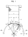
- the wing traverse apparatus 1 is comprised of a traverse guide 10 that guides the yarn along a traverse track, and a set of traverse wings 4, 5 arranged one in front of the other that traverse the yarn Y that is taken up into a package P.
- the traverse apparatus 1 is also provided with a driving device 6 (see Figure 4) that rotates the traverse wings 4, 5 and laterally shifts both the traverse wings 4, 5 and the traverse guide 10.
- the rotary centers 02, 03 of the traverse wings 4, 5 are arranged eccentrically in the lateral (traverse) direction.
- Traverse guide 10 is comprised of a right traverse guide plate 2 and a left traverse guide plate 3.
- lateral yarn transfer points a, b points where the traverse direction of the yarn is reversed
- the traverse guide plates 2, 3 form a guiding contour 7 along the traverse track between the yarn transfer points a, b.
- the guiding contour 7 is comprised of a flat section 7a that runs parallel to the axis of the package P, a curved section 7b formed radially around the rotary centers 02, 03 of the traverse wings 4, 5 and extending from the end of the flat section 7a to the yarn transfer points a, b, and a reverse straight section 7c where the yarn reverses direction, formed parallel to the axis of the package P.
- the traverse guide plates 2, 3 are arranged one in front of the other.
- the left guide plate 3 is coupled to the traverse wing 5 via a shaft at the rotary center 03 of the traverse wing 5, the axis arranged eccentrically to the right of the rotary center 02 of the other traverse wing 4.
- the right traverse guide plate 2 is coupled to the traverse wing 4 via a rotary shaft at the rotary center 02 of the traverse wing 4.
- the traverse guide plates 2, 3 partially overlap, and bring the yarn transfer points a, b into symmetrical alignment.
- the traverse wings 4, 5 are arranged in parallel planes with the traverse guide plates 2, 3.
- the traverse wing 4 is arranged between the two traverse guide plates 2, 3, and rotates freely around the rotary center 02 (rotary shaft) on the side of the yarn transfer point b.
- the traverse wing 5 is arranged between the traverse wing 4 and the traverse guide plate 3, and rotates freely around the rotary center 03 (rotary shaft) on the side of the yarn transfer point a.
- Each of the traverse wings 4, 5 are formed in point symmetry relative to their respective rotary centers 02, 03 (rotary shafts).
- Wing tip sections 4a, 4b are formed on either side of the traverse wing 4, separated 180 degrees in the direction of rotation from each other.
- wing tip sections 5a, 5b are also formed on either side of the traverse wing 5, again separated 180 degrees in the direction of rotation.
- Each wing tip section 4a, 4b, 5a, 5b is provided with a yarn release point c arranged at the end of the respective tip on a central axis running lengthwise through the middle of the respective traverse wing 4, 5.
- Yarn guiding surfaces 8, 9 extend away from the yarn release point c at 45 degrees angles to the yarn release point c.
- the angle ⁇ at which the yarn guiding surfaces 8, 9 extend away from their respective yarn release point c need not be set at 45 degrees, but it should preferably be set at an angle ⁇ at which the guiding surfaces 8, 9 and the track f along which the rotary centers 02, 03 of the traverse wings 4, 5 are moved become parallel.
- the traverse wings 4, 5 rotate in opposite directions.
- the yarn release point c of the traverse wing 4 aligns with the yarn transfer point a, and the yarn guiding surfaces 8 on each of the wing tip sections 4a, 4b, 5a, 5b become parallel to the straight section 7c of the traverse guide plate 2.
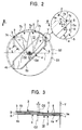
- the yarn release point c of the traverse wing 5 aligns with the yarn transfer point b, and the yarn guiding surfaces 9 on each of the wing tip sections 4a, 4b, 5a, 5b become parallel to the straight section 7c of traverse guide plate 3 (See Figure 2).
- the traverse wings 4, 5 have rotational tracks S1, S2, respectively, that extend slightly beyond the periphery of their respective traverse guide plate 2, 3.
- the rotational track S1 of the traverse wing 4 passes through the yarn transfer point a
- the rotational track S2 of the traverse wing 5 passes through the yarn transfer point b.
- the traverse wing 4 rotates clockwise, with the traverse wing 5 rotating counter-clockwise.
- the traversed yarn Y is guided along the curved section 7b of the traverse guide plate 2, moving along the yarn guiding surface 9 of the traverse wing 4 towards release point c as the yarn Y and the traverse wing 4 approach the yarn transfer point a.
- the yarn release point c of the traverse wing 4 meets the yarn transfer point a, the yarn Y slides past the release point c and is released from the traverse wing 4.
- the yarn guiding surface 8 of the traverse wing 5 aligns with and becomes parallel to the straight section 7c of the traverse guide plate 2, and the yarn Y released by the traverse wing 4 is smoothly transferred to the guiding surface 8 of the traverse wing 5.
- the yarn Y is then traversed to back to the yarn transfer point b where the same process is repeated, thus smoothly and continuously traversing the yarn Y between the traverse wings 4, 5.
- the yarn Y is taken up into package P at a traverse width T equal to the distance between the two yarn transfer points a, b. Since the yarn Y is always transferred at the yarn transfer points a, b by the traverse wings 4, 5 and the traverse guide plates 2, 3 as described above, the traverse width can be stabilized, enabling nice packages P to be regularly produced.
- the traverse guide plates 2, 3 and the traverse wings 4, 5 are driven by the driving device 6 shown in Figure 4.
- the driving device 6 is provided with a pair of freely rotatable pulleys 15 at the rotary centers 02 and 03.
- the rotation of the pulleys 15 rotates the respective traverse wings 4,5 independently of the traverse guide plates 2, 3.
- the driving device 6 is also provided with a pair of sliders 16 ("guiding mechanisms") which slide the respective rotary centers 02, 03 in the axial plane of the package P.
- the sliders 16 are arranged one in front of the other so that they do not interfere with each other.
- the sliders 16 apply force to the rotary centers 02, 03, pushing them away from each other.
- Each pulley 15 is connected to a transmission pulley 18 via a timing belt 17.
- the timing belts 17 are guided by rollers positioned outside thereof, and extends to the transmission pulleys 18.
- Each transmission pulley 18 is engaged with a rotary conversion mechanism 19 through a respective output shaft on the rotary conversion mechanism 19.
- the rotary conversion mechanism 19 is connected to a pulley 24 of a driving motor 23 via input-side pulley 20, transmission pulley 21, and timing belt 22.
- the rotary conversion mechanism 19 imparts rotation in the opposite direction to each of the transmission pulleys 18 arranged on the input side of the driving motor 23, and therefore may be comprised as a gear, a pulley, a timing belt, etc.
- the driving motor 23 of the driving device 6 rotates the timing belt 22, and the pulleys 20 and 21, providing input to the rotary conversion mechanism 19.
- the rotary conversion mechanism 19 rotates the respective pulleys 18, 18 in opposite directions, thereby imparting rotation via the timing belts 17, 17 to the rotary axis pulleys 15, 15. This rotates the traverse wings 4, 5 in opposite directions.
- the driving device 6 is also provided with a ball screw 25.
- the ball screw 25 is comprised of a ball screw shaft 26, and a pair of nuts 27, 28, namely, an upper nut 27 and a lower nut 28.
- the ball screw shaft 26 engages with a bevel gear 29 which is driven by a driving source (not shown in the drawing).
- the upper nut 27 supports the rotary conversion mechanism 19, and the lower nut 28 rotatably supports the transmission pulley 21.
- the input-side pulley 20, the transmission pulley 21, and the timing belt 22 on the input side of the rotary conversion mechanism 19 are all arranged between the upper nut 27 and the lower nut 28 of the ball screw 25.
- the timing belt 22 is guided on the outside of the belt by rollers, and extends to a pulley 24 on the driving motor 23. It should be noted that the pulley 20 can be connected directly to the driving motor 23, and the driving motor 23 can be arranged so as to move vertically.
- the driving device 6 elevates the rotary conversion mechanism 19 and the transmission pulley 21. This is accomplished by rotation of the ball screw shaft 26 by the driving source, which causes the upper and lower nuts 27, 28 to elevate, thereby lifting the rotary conversion mechanism 19 and the transmission pulley 21.
- the sliders 16 are pushed in opposite directions by the force operating against them, moving with their respective timing belts 17, thus moving the rotary centers 02, 03 away from each other (in the axial plane of the package P). This consequently increases the eccentricity ⁇ between the rotary centers 02, 03.
- the rotating the ball screw shaft 26 in reverse pulls the rotary centers 02, 03 closer together, decreasing the eccentricity ⁇ between the rotary centers 02, 03.
- the traverse wing 4 moves with the traverse guide plate 2, and the traverse wing 5 moves with the traverse guide plate 3, enabling adjustment in the traverse width T.
- increasing the eccentricity ⁇ between the rotary centers 02, 03 of the traverse wings 4, 5 decreases the traverse width T, while reducing the eccentricity ⁇ increases the traverse width T.
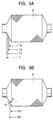
- the wing traverse apparatus 1 allows the eccentricity ⁇ between the rotary centers 02, 03 of the traverse wings 4, 5 to be adjusted by adjusting the relative positions of the rotary centers 02, 03, thereby allowing the yarn Y's traverse width T to be adjusted. Consequently, by gradually decreasing the traverse width T, T1, T2, T3, over time, as shown in Figure 6, the package P with a tapered end can be formed.
- the apparatus By comprising the apparatus such that the contours of the traverse wings 4, 5 at the yarn transfer points a, b become parallel with the track in which the rotary centers 02, 03 are slid, and by moving the traverse guide plates 2, 3 in concert with the rotary centers 02, 03, the yarn Y can be uniformly transferred even when the rotary centers 02, 03 are moved.
- the package winding density across the traverse width T can be held constant.
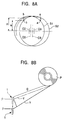
- the traverse guide plate 11 may need to be formed to a particular curved contour. This curved contour should set both a constant rotary angle ⁇ 1 of the traverse wings 4, 5, and a constant winding width increment h.
- the rotary shafts of the traverse wings 4, 5 should be coupled to their respective traverse guide plates 2, 3 formed as the curved contour as shown in Figure 7.
- the traverse apparatus 1 of the present invention setting the angle ⁇ of the tip sections of the traverse wings 4, 5 to 45 degrees allows the height of the yarn transfer points a, b relative to the rotary centers 02, 03 to be held constant.
- the traverse wings 4, 5 in shapes other than those shown in Figures 1 to 4 may be employed by the wing traverse apparatus 1 of the present invention, for example, one in which the angle ⁇ of the tip sections of the traverse wings 4, 5 is set to approximately 90 degrees or 90 degrees.
- the angle of the tip sections in the area at which the traverse wings 2, 3 approach each other and reach the yarn transfer point should preferably be 45 degrees or approximately 45 degrees.
- the take-up winder 51 of Figure 9 winds a yarn Y being unwound from a supply bobbin E on a frame 52, passes the yarn Y through feed rollers 54, 55 and the wing traverse apparatus 1, and winds it into a package P on a bobbin B, which is rotated by a drum 56.
- the take-up winder 51 is provided with a cradle 57 that holds both ends of the bobbin B.
- the bobbin B is held in pressured contact with the drum 56.
- the cradle 57 is attached to the frame 52 such that it is pivotable against the frame 52, and it pivots as the package P grows into a full package, the cradle 57 pivoting such that it moves away from the drum 56.
- the wing traverse apparatus 1 is arranged between the feed roller 55 and the drum 56, and is attached to the frame 52.
- the wing traverse apparatus 1 is connected on the beveled gear 29 side of the ball screw 25 to the cradle 57 via a planetary bevel gear train 58, a gear mechanism 59, a lever mechanism (not shown in the diagram), a pulley 60, and a timing belt 61.
- wing traverse apparatus 1 allows the eccentricity between the rotary centers 02, 03 to be adjusted through the pivoting of the cradle 57.
- the lever mechanism is used in shaping the package. Specifically, in order to keep the sides of the package from bulging outwards because the contact pressure against the package, the package ends are made to be convex. The lever helps make the convex form.
- the wing traverse apparatus 1 is also connected to a folding-fan shaped segment gear 63 via the planetary bevel gear train 58 and the gear mechanism 62, as shown in Figure 10.
- a segment gear 63 is rotated by a circular cam plate 65 of a driving motor 64, thus enabling the wing traverse apparatus 1 to perform the creeping operation.
- the cradle 57 takes hold of bobbin B, and the drum 56 is held in contact pressure with the bobbin B as the cradle 57 is pivoted, rotating the ball screw 25 (and the ball screw shaft 26). This changes the eccentricity ⁇ between the rotary centers 02, 03 of the traverse wings 4, 5.
- the traverse width of the wing traverse apparatus 1 is T.
- the drum 56 With the take-up winder 51 in this state, the drum 56 is driven, rotating the bobbin B.
- the driving motor 23 drives the traverse wings 4, 5 in opposite directions.
- the yarn Y being unwound from the supply bobbin E is then traversed by the wing traverse apparatus 1, and wound into a package P around the bobbin B.
- the tapered shape of the package P can be adjusted.
- the rotation of ball screw 25 (and the ball screw shaft 26) via the segment gear 63 and the planetary bevel gear train 58 can be reversed periodically, allowing the traverse width at which the package is wound to be periodically alternated between gradual narrowing and gradual widening, thus performing the creeping operation.
- the creeping parameters can be adjusted by changing the shape of the circular cam plate 65 and the rotary speed of the cam. As should be clear, the creeping operation helps to prevent the package P from saddle-bagging at the ends.
- the wing traverse apparatus of the present invention changes the distance separating the rotary centers of a set of traverse wings, thus moving the yarn transfer points in the direction of the yarn traverse. This allows creeping to be performed, or may allow the formation of a package with tapered ends.
- the traverse guide is comprised as a pair of guide plates, and when the guide plates are moved in concert with the shifting of the rotary centers of the traverse wings, the yarn transfer points remain precisely in the tracks of the traverse wings even though the rotary centers of the traverse wings are shifted. Consequently, the vertical distance separating the yarn transfer points and the rotary centers can be held constant, and the yarn transfer operation can be performed smoothly all the time.
- the yarn transfer points on the guide plates can be matched to the tracks of the traverse wings with even greater precision, and the yarn transfer operation can be performed even more smoothly. This even despite the fact that the rotary centers are shifted.
Landscapes
- Engineering & Computer Science (AREA)
- Textile Engineering (AREA)
- Winding Filamentary Materials (AREA)
- Spinning Or Twisting Of Yarns (AREA)
Applications Claiming Priority (2)
| Application Number | Priority Date | Filing Date | Title |
|---|---|---|---|
| JP24286499 | 1999-08-30 | ||
| JP24286499A JP2001063915A (ja) | 1999-08-30 | 1999-08-30 | 羽根トラバース装置 |
Publications (2)
| Publication Number | Publication Date |
|---|---|
| EP1081081A2 true EP1081081A2 (de) | 2001-03-07 |
| EP1081081A3 EP1081081A3 (de) | 2002-03-20 |
Family
ID=17095397
Family Applications (1)
| Application Number | Title | Priority Date | Filing Date |
|---|---|---|---|
| EP00117550A Withdrawn EP1081081A3 (de) | 1999-08-30 | 2000-08-14 | Traversiervorrichtung mit rotierenden Flügeln |
Country Status (2)
| Country | Link |
|---|---|
| EP (1) | EP1081081A3 (de) |
| JP (1) | JP2001063915A (de) |
Cited By (1)
| Publication number | Priority date | Publication date | Assignee | Title |
|---|---|---|---|---|
| CN106270740A (zh) * | 2016-08-29 | 2017-01-04 | 浙江奇爱管业有限公司 | 一种波纹管切割装置 |
Families Citing this family (1)
| Publication number | Priority date | Publication date | Assignee | Title |
|---|---|---|---|---|
| CN103221324B (zh) * | 2010-11-20 | 2014-12-31 | 欧瑞康纺织有限及两合公司 | 用于卷绕长丝的设备 |
Family Cites Families (2)
| Publication number | Priority date | Publication date | Assignee | Title |
|---|---|---|---|---|
| DE3345237A1 (de) * | 1983-12-14 | 1985-06-27 | Barmag Barmer Maschinenfabrik Ag, 5630 Remscheid | Aufspulmaschine |
| DE3664131D1 (en) * | 1985-03-15 | 1989-08-03 | Barmag Barmer Maschf | Winding machine |
-
1999
- 1999-08-30 JP JP24286499A patent/JP2001063915A/ja active Pending
-
2000
- 2000-08-14 EP EP00117550A patent/EP1081081A3/de not_active Withdrawn
Cited By (2)
| Publication number | Priority date | Publication date | Assignee | Title |
|---|---|---|---|---|
| CN106270740A (zh) * | 2016-08-29 | 2017-01-04 | 浙江奇爱管业有限公司 | 一种波纹管切割装置 |
| CN106270740B (zh) * | 2016-08-29 | 2019-03-19 | 浙江奇爱管业有限公司 | 一种波纹管切割装置 |
Also Published As
| Publication number | Publication date |
|---|---|
| EP1081081A3 (de) | 2002-03-20 |
| JP2001063915A (ja) | 2001-03-13 |
Similar Documents
| Publication | Publication Date | Title |
|---|---|---|
| KR100310357B1 (ko) | 감김웨브롤을감는방법및장치 | |
| JP2614488B2 (ja) | 貯蔵装置 | |
| CA2127125C (en) | Belt transfer section and method of use for right angle blank feeder | |
| CA1299078C (en) | Apparatus with a rotating device for gluing the end portion of materialwound onto reels | |
| CA1212091A (en) | Traverse take-up apparatus for material of indefinite length | |
| US3917250A (en) | Strip laying apparatus | |
| EP1081081A2 (de) | Traversiervorrichtung mit rotierenden Flügeln | |
| CN219618503U (zh) | 打印喷头连接结构 | |
| US3823886A (en) | Apparatus for winding materials, such as threads, yarns or bands into cross-wound bobbins | |
| CN222023806U (zh) | 一种高速焊带涂锡机焊带收卷装置 | |
| US5277668A (en) | Gear transmissions, for textile machines | |
| JPH01501703A (ja) | リボン巻き防止法 | |
| EP0768269B1 (de) | Vorrichtung zum Aufspulen mehrerer Garne | |
| EP0834462B1 (de) | Aufwickelvorrichtung | |
| KR20000029294A (ko) | 실 안내 장치 | |
| CA1101395A (en) | Bobbin winder | |
| US6726142B2 (en) | Twist controlling device, rotatable nip and axial feed system | |
| JPH01242360A (ja) | 紙葉類堆積繰出し機構 | |
| CN222974482U (zh) | 一种包装材料加工用卷曲装置 | |
| CN116946776B (zh) | 一种同步放卷机构 | |
| JPH0236501B2 (de) | ||
| KR100457402B1 (ko) | 와인더의 트레버스 구동장치 | |
| CN223605015U (zh) | 一种箭杆缠布机 | |
| KR930011633B1 (ko) | 환편기(丸編機)에 있어서의 편지(編地)이송용 롤에의 동력전달장치 | |
| SU1603448A1 (ru) | Раскладчик провода |
Legal Events
| Date | Code | Title | Description |
|---|---|---|---|
| PUAI | Public reference made under article 153(3) epc to a published international application that has entered the european phase |
Free format text: ORIGINAL CODE: 0009012 |
|
| AK | Designated contracting states |
Kind code of ref document: A2 Designated state(s): AT BE CH CY DE DK ES FI FR GB GR IE IT LI LU MC NL PT SE |
|
| AX | Request for extension of the european patent |
Free format text: AL;LT;LV;MK;RO;SI |
|
| PUAL | Search report despatched |
Free format text: ORIGINAL CODE: 0009013 |
|
| AK | Designated contracting states |
Kind code of ref document: A3 Designated state(s): AT BE CH CY DE DK ES FI FR GB GR IE IT LI LU MC NL PT SE |
|
| AX | Request for extension of the european patent |
Free format text: AL;LT;LV;MK;RO;SI |
|
| STAA | Information on the status of an ep patent application or granted ep patent |
Free format text: STATUS: THE APPLICATION HAS BEEN WITHDRAWN |
|
| 18W | Application withdrawn |
Withdrawal date: 20020611 |