EP1081090A2 - Dispositif pour fermer des bouteilles avec une fermeture à étrier - Google Patents
Dispositif pour fermer des bouteilles avec une fermeture à étrier Download PDFInfo
- Publication number
- EP1081090A2 EP1081090A2 EP00118958A EP00118958A EP1081090A2 EP 1081090 A2 EP1081090 A2 EP 1081090A2 EP 00118958 A EP00118958 A EP 00118958A EP 00118958 A EP00118958 A EP 00118958A EP 1081090 A2 EP1081090 A2 EP 1081090A2
- Authority
- EP
- European Patent Office
- Prior art keywords
- plug
- bottles
- bottle
- machine according
- star
- Prior art date
- Legal status (The legal status is an assumption and is not a legal conclusion. Google has not performed a legal analysis and makes no representation as to the accuracy of the status listed.)
- Granted
Links
- 238000007689 inspection Methods 0.000 claims description 35
- 238000007789 sealing Methods 0.000 claims description 12
- 230000007704 transition Effects 0.000 claims description 4
- 241001411320 Eriogonum inflatum Species 0.000 claims description 3
- 230000003287 optical effect Effects 0.000 claims description 2
- 238000011144 upstream manufacturing Methods 0.000 claims description 2
- 238000011282 treatment Methods 0.000 description 16
- 229920001971 elastomer Polymers 0.000 description 11
- 239000005060 rubber Substances 0.000 description 11
- 230000033001 locomotion Effects 0.000 description 9
- 238000012546 transfer Methods 0.000 description 4
- 230000002950 deficient Effects 0.000 description 3
- 239000007788 liquid Substances 0.000 description 3
- 239000007921 spray Substances 0.000 description 3
- 238000012360 testing method Methods 0.000 description 3
- 210000001015 abdomen Anatomy 0.000 description 2
- 230000004888 barrier function Effects 0.000 description 2
- 230000000694 effects Effects 0.000 description 2
- 230000004913 activation Effects 0.000 description 1
- 235000013405 beer Nutrition 0.000 description 1
- 230000008901 benefit Effects 0.000 description 1
- 239000000969 carrier Substances 0.000 description 1
- 230000008859 change Effects 0.000 description 1
- 238000004140 cleaning Methods 0.000 description 1
- 230000008878 coupling Effects 0.000 description 1
- 238000010168 coupling process Methods 0.000 description 1
- 238000005859 coupling reaction Methods 0.000 description 1
- 230000003247 decreasing effect Effects 0.000 description 1
- 230000007717 exclusion Effects 0.000 description 1
- 238000005429 filling process Methods 0.000 description 1
- 238000002594 fluoroscopy Methods 0.000 description 1
- 239000006260 foam Substances 0.000 description 1
- 238000005187 foaming Methods 0.000 description 1
- 230000003993 interaction Effects 0.000 description 1
- 239000008258 liquid foam Substances 0.000 description 1
- 238000012544 monitoring process Methods 0.000 description 1
- 238000003825 pressing Methods 0.000 description 1
- 238000005096 rolling process Methods 0.000 description 1
- 238000012216 screening Methods 0.000 description 1
- 230000011664 signaling Effects 0.000 description 1
- 230000001360 synchronised effect Effects 0.000 description 1
Images





Classifications
-
- B—PERFORMING OPERATIONS; TRANSPORTING
- B67—OPENING, CLOSING OR CLEANING BOTTLES, JARS OR SIMILAR CONTAINERS; LIQUID HANDLING
- B67B—APPLYING CLOSURE MEMBERS TO BOTTLES JARS, OR SIMILAR CONTAINERS; OPENING CLOSED CONTAINERS
- B67B1/00—Closing bottles, jars or similar containers by applying stoppers
- B67B1/08—Securing stoppers, e.g. swing stoppers, which are held in position by associated pressure-applying means coacting with the bottle neck
Definitions
- the invention relates to a machine for treating bottles that can be closed with swing top closures, especially for inspecting and / or putting on the Cap on the bottle mouth and if necessary, tensioning the bow lock with a on its outer circumference with recording places Turntable and one upstream and downstream of the turntable Inlet and outlet star with arranged on the outer circumference Recording places for the bottles, each Location of the turntable means for holding the Bottle in a rotary position with on the side Bottleneck and facing the center of the turntable attached plug and a cam-controlled Fork are assigned to the with their fork branches Clasp catches on the side next to the plug and the plug from its initial position laterally at the bottle neck in a raised, from the bottle neck and Bottle head transferred spaced alignment position, in a driven alignment element in it at least one suitable for inspection and / or fitting Position turns and holds.
- a known machine for putting on the Cap on the bottle mouth of the entrance mentioned type (EP 0 353 534 B1) has a number of inputs, Intermediate and outlet stars connected Rotary tables, each for different treatments are set up. So in the first turntable Bottle in its rotating position with respect to the Snap lock aligned so that in the second Turntable of the stopper on the bottle neck to the center of the turntable and in this rotary position curve-controlled clamps attacking the bottle belly is held against rotation. After using the cam-controlled fork free on the top bracket rotating plug in one position raised to the side next to and above the bottle mouth the alignment element takes effect.
- the Alignment element consists of a profiled Alignment wheel with one tangential from its periphery outgoing sliding guide.
- Another known treatment machine for Swing top bottles (EP 0 512 539 B1), specifically for Inspect the locking plugs of the clip locks, differs from the machine of the beginning mentioned type in the means by which the Plug into a suitable one for inspection Position. With this machine, the Alignment of the rotational position of the bottles and the subsequent inspection of the closure plugs at in Axial spaces between a rotary table Bottle head and bottle base clamped and non-rotatable held bottles instead. Are on this machine the plugs are different from the described other known machine on the Center of the turntable facing away from the bottles.
- the invention has for its object a Treatment machine for swing top bottles too create the basic concept for both Inspect as well as put on the plug the bottle mouth is suitable.
- the rotational alignment the swing top bottles already in the inlet star the rotary table can be placed at free bottle head exclusively with means for Moving and aligning the plug be it that these means the plug in the position suitable for various inspections bring, be it that these means the plug put on the bottle mouth.
- the means for aligning the plug for the inspection are also the means with which the stopper on the bottle mouth is put on. This also means that the Machine manufacturers no longer have two different types of machines for inspection and for putting on the stopper on the bottle mouth and if necessary, closing the clip closure for Must provide. For the different The same machine only partially needs types of treatment to be equipped with other functional elements.
- the rotary drive is stationary in the inlet star outside along the transport route of the bottles in the Inlet star extending, the bottles in the Frictional support and holding places Has guide element on the rotating Inlet star that can be freely rotated in the receiving areas bottles held unroll, and that means to Lock the bottles one by one cam-controlled Swivel arm carried over the bottle head on the Lowerable bottle head and with the lower bracket of the Interlocking stop / detent and one that only releases the swivel arm, the one on the bottle neck locking pawl if the plug is not in the Scanning range.
- the support and Guide element be a rigid arch guide, but it is preferably a tape.
- the tape can be used as Continuous belt should be designed and driven, provided that resulting rotary motion from the rolling motion should be increased or decreased.
- the driven alignment element that acts on the plug when it is off the fork is held in a manner known per se as profiled Wheel with tangential adjoining the periphery Be designed as a sliding guide, but it is constructive much easier if the alignment element is finger-like and is profiled and from above between the The stopper is freely rotatable on the upper bracket Fork branches and twisting of the plug so far is insertable until the plug in the desired position is reached.
- Such one Finger-like rotating and aligning element is in itself known, but it acts in the prior art on the Outside of the swing top bottles and not, as with of the invention, on the inside of the bottles. Therefore it can also be according to a further embodiment of the Invention in cooperation with the fork serve the plug in the correct position on the To put the bottle mouth on, and when it comes after at the top in an arch to the bottle mouth reaching sliding guide passes.
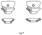
- the profiling of the finger-like turning and Alignment element can be arranged one above the other and have different shapes from each other, that of shape of the plug in different rotational positions correspond. That way it can be used for various inspections take optimal positions, for a frontal view of the rubber seal, an oblique view to check the system of the Sealing rubbers or a frontal view of the front for capturing a logo on the front.
- the turntable Stopper placed on the bottle mouth has been, be it with an empty bottle or with filled bottle, then you can use proportionally close the bottle with little effort.
- that the outside of the outlet star in the transport path of the clamping bracket the one placed on the bottle mouth Closure plugs not yet tensioned clasp closures such a forced guidance curve running stationary is arranged that from her the tension bracket in his Closing position is transferred.
- the Forced guidance curve resiliently supported on the one hand to avoid overload and on the other hand one Prerequisite for monitoring the closing voltage too create. With a properly sealed bottle namely the closing voltage must a certain Have minimum value.
- the closing tension can be at a spring-loaded positive guidance curve already at Check that the curve is closed Path sensor for whose alternative path is assigned.
- the Closing tension can also be done by this ensure that every pick-up place of the discharge star one in the opening direction on the clip lock acting spring-loaded handle. Is that enough Closing tension not off, then the handle opens due to the adjusted spring force the clip lock again.
- the path of the handle in the opening direction through a Control curve is limited.
- the way is like this widely limited that opening the clasp is currently possible.
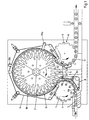
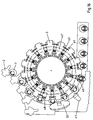
- the bottle treatment machine according to FIG. 1 consists of an inlet star 1, a turntable 2 and one Outlet star 3. These machine parts each have the External circumference of admission places 4,5,6 for those to be treated Bottles 7, namely swing top bottles, on.
- the Bottles 7 on the bottle belly on freely rotatable Rollers 4a, 4b are supported and in it by one stationary, frictional support and Guide element 8 held as the endless belt 8th can be trained.
- the endless belt 8 is preferably by means of deflection rollers 8a in several, in particular three sections 8b, 8c, 8d split to better adapt to the transport route to reach the bottles 7. It also affects in the event of a disturbance in the rotary motion, if on a short distance 8c the drive stops then again starts.
- the bottles are no longer turned, but held in rotation.
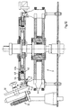
- the bottles 7 are used for this purpose in their receiving places 5 endless tensioning strap 9, which has a plurality of carriers 10 of the Turntable 2 synchronized with rotates.
- each recording place is 4 Means for locking the bottle 7 in a particular Rotational position in relation to the position of its bow lock 7a assigned.
- These funds consist of one with the Interacting lower bracket of the bow lock 7a Stop and / or a rest, especially in the form of a Fork with a rest 12 on one fork and one Stop on the other fork load by one two-piece swivel arm 13a, 13b is carried and by a weight 13c loaded from above onto the bottle head is lowerable.
- the movement of the swivel arm 13 is cam controlled. This is done by a in a fixed curve 14 engaging scanning element 15.
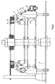
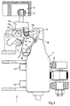
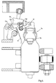
- the curve 14 is like this designed that the latch 12 is raised when a Bottle enters the inlet star 1 and when it Leaving star 1 leaves. Between these two positions the rotation alignment takes place. Since it is desired that the bottle 7 the inlet star 1 with the outside Sealing plug 16 leaves, as shown in Figure 5 is, the rest 12 but both in this position and in a position offset by 180 °, which is shown in FIG is shown, could basically snap into place on the swivel arm 13 a the plug 16 scanning pawl 17 with a part 13a of the swivel arm 13a, 13b supporting roller 17a in such a way that in the scanning range of the pawl 17th lying plug 16, as shown in Figure 3, the latch 12 can not engage, while not in Scanning range lying plug 12, as it is for the transfer of the bottle 7 to the turntable 2 is desired is and shown in Figure 4, the pawl 17th the rest 12 releases, so that the upper bracket 18 in the rest 12 can snap into place.
- a spray device S is arranged with three spray heads S 1 , S 2 , S 3 , with which cleaning liquid on the functional elements coming into contact with the clip closure 7 a including the closure plug 16 and the bottle head the passage of which can be sprayed.
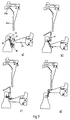
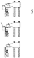
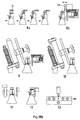
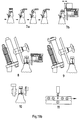
- the one functional element consists of a fork 21 carried by an arm 22 is, the movement of a groove curve 23 directly and indirectly via a coupling 24 from one Groove curve 25 is derived, so that the fork 21 the Cap 16 on the next to the bottle head and Bottleneck-indicated path moves, as in Figure 7a is shown.
- the fork 21 of on top of the top bracket 19 next to the plug 16 pressed, whereby the upper bracket 19 and lower bracket 18 a Assume stretched position and the tensioning bracket 33 at a distance brought from the bottle head, as shown in Figure 7b is.
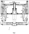
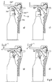
- the second functional element which is shown in detail in FIG. 8 is shown as a finger-like, with a Rotary and alignment element 26 provided with a tooth profile trained, which is only a curve-controlled, linear Performs lifting movement. For this it becomes, as in FIG remove is carried by a guide tube 27, the by a spring 28 via a scanning roller 29 against one one-sided curve 30 is pressed.
- the toothed area 26a can have a different profile.
- the Profiling can be adjusted so that the Closure plug 16 different defined Assumes rotational positions when in the raised position above the level of the bottle mouth (Figure 7d) finger-like rotating and aligning element 26 between the Forks of fork 21 retracts and in Touch contact moved past the plug 16 becomes.
- the one gliding element 26b * can be a scanning element A wear that in cooperation with a stationary on Transport path of the sensors positioned in bottles, e.g. a light barrier L gives a signal when a Plug 16 wrong on the bottle mouth is seated, as shown in Fig. 8d.
- the bottles From the turntable 2, the bottles arrive in receiving positions 6 of the discharge star 3, in which they are held in a rotationally fixed manner in the transferred rotational position by forks G, which support with their fork branches G 1 , G 2 on both sides of the lower bracket 18, where it is stored in blind holes in the bottle head is.
- they pass the area of a fixed deflector 31, which is arranged in such a way that it throws out an incorrectly seated plug 16, as shown in FIG.
- the closure plug 16 can be ejected by a ejector 48 arranged in a stationary manner on the transport path, which can be activated by a control command, for example of the test means described, from the scanning element A and the light barrier L.
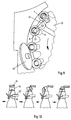
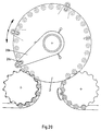
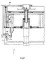
- FIGS. 9, 11 to 13 show the locking wheel 32 lies in the transport path of the clamping bracket 33 the not yet tensioned clip closures 7a, so that by pressing the locking wheel 32 on the clamping bracket 33 these are transferred to the closed position, as in Figures 12 and 13 is shown.
- the locking wheel 32 is in each supported on a spring 34 to it, however also to protect the bow lock 7a from overload. This resilient support can also, however, according to FIG can be used to check the closing force.
- the bias of the spring 34 can be set on an adjusting screw 42a and on the other hand, the movement of the closing wheel 32 Path sensor is assigned.
- the closing wheel 32 Path sensor For this carries a guide sleeve 35, on which the locking wheel 32 is mounted, one Stylus 36, which cooperates with a sensor 37. If the closing force of the Bow lock 7a is not large enough then the locking wheel 32 transfers the clamping bracket 33 into its closed position, but not the sleeve 35 moved against the force of the preset spring 34. As a result, the sensor 37 does not receive a signal, resulting in one Control command for activation of a subordinate Ejector 49 is implemented.
- FIGs 12 and 13 Another way of checking the closing force is in Figures 12 and 13 shown.
- the embodiment is on the locking wheel 32 opposite side of bottle 7 each Recording place 6 assigned a pusher 41, the radial outward from one in bias with one Set screw 42a adjustable support spring 42 loaded is.
- This pusher 41 acts on the joint between Upper bracket 19 and lower bracket 18 in the opening direction.
- the closing force of the clasp 7a after Closing is not sufficiently large, is caused by the Pusher 41 of the clasp 7a opened again.
- Around the. can limit this radial movement to the outside Lever 41 with a roller 43 in a groove curve 44 be guided, the course of which is shown in Figure 11.
- Figure 11 it is further shown that following the closing of the bow locks is checked whether the clip locks are properly closed or Not.
- Figure 14 shows the individual phases of Closing pressure check one with insufficient Closing force of closed bottle 7.
- the swing top 7a is opened again, which of the on the clamp 33 appealing test device 47 is recognized.
- the control curve according to FIG. 16 is used when it's about checking the buckles from unfilled bottles 7 goes.
- the exclusive Checking unfilled bottles 7 is useful because then only after defective bottles 7 have been removed Bottles of a filling machine that can be properly sealed be fed. This reduces the committee of improperly closed filled bottles 7.
- Figure 17 shows two sealing plugs, the with differently profiled rubber seals are.
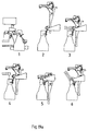
- Figures 18a and 18b are in chronological order Order the different phases of the inspection shown.
- the rotation is aligned the bottle in the inlet star 1.
- the plug 16 is raised and one after the other in cooperation with one of the form of the Plug 16 adapted profiling of toothed rotating and aligning element 26 in different Positions brought to him regarding various Criteria such as the area of the sealing rubber, shape of the Sealing rubbers (see Figure 13) and the presence check a logo on the front.
- the plug 16 will work together of fork 21 and arcuate slide guide 26b over the Mouth of the bottle moved and then on the Bottle mouth put on.
- phase 7 the turning and Alignment element raised and thereby the neck area the bottle for fluoroscopy and inspection Approved.
- phase 8a the bottle passes through the Transfer to the outlet star 3 a deflector 31, the not properly seated on the bottle mouth Closure plug 16 throws off.
- phase 8b becomes an improperly seated Plug 16 from an activatable ejector 48 thrown off.
- phases 9 and 10 in the outlet star 3 the clamp closure 7a is tensioned. Usually is this with a check of the closing voltage and if the closing tension is insufficient, opening the Bow lock 7a connected. In phase 11 then the check of the locking bracket.
- phase 12 can by forced opening of the Bow lock 7a can be released again.
- phase 13 defective bottles are ejected in the entire run, be it in the turntable or in the Discharge star, have been determined.
Landscapes
- Engineering & Computer Science (AREA)
- Mechanical Engineering (AREA)
- Specific Conveyance Elements (AREA)
- Sealing Of Jars (AREA)
- Filling Of Jars Or Cans And Processes For Cleaning And Sealing Jars (AREA)
- Bag Frames (AREA)
- Closing Of Containers (AREA)
- Seal Device For Vehicle (AREA)
Applications Claiming Priority (10)
| Application Number | Priority Date | Filing Date | Title |
|---|---|---|---|
| DE19941521 | 1999-09-01 | ||
| DE19941521 | 1999-09-01 | ||
| DE19953917 | 1999-11-10 | ||
| DE19953917 | 1999-11-10 | ||
| DE19956345 | 1999-11-24 | ||
| DE19956345 | 1999-11-24 | ||
| DE10001748 | 2000-01-17 | ||
| DE10001749 | 2000-01-17 | ||
| DE10001748 | 2000-01-17 | ||
| DE10001749 | 2000-01-17 |
Publications (3)
| Publication Number | Publication Date |
|---|---|
| EP1081090A2 true EP1081090A2 (fr) | 2001-03-07 |
| EP1081090A3 EP1081090A3 (fr) | 2001-09-05 |
| EP1081090B1 EP1081090B1 (fr) | 2003-07-09 |
Family
ID=27512359
Family Applications (1)
| Application Number | Title | Priority Date | Filing Date |
|---|---|---|---|
| EP00118958A Expired - Lifetime EP1081090B1 (fr) | 1999-09-01 | 2000-09-01 | Dispositif pour fermer des bouteilles avec une fermeture à étrier |
Country Status (3)
| Country | Link |
|---|---|
| EP (1) | EP1081090B1 (fr) |
| AT (1) | ATE244680T1 (fr) |
| DE (1) | DE50002809D1 (fr) |
Cited By (2)
| Publication number | Priority date | Publication date | Assignee | Title |
|---|---|---|---|---|
| AT503868B1 (de) * | 2006-09-28 | 2008-01-15 | Jarolim Innovative Automation | Lager- und transporteinrichtung für bügelverschlüsse von behältnissen |
| CN110963263A (zh) * | 2018-09-29 | 2020-04-07 | 廊坊市代宇包装机械有限公司 | 一种摇摆盖的自动封盖设备 |
Citations (3)
| Publication number | Priority date | Publication date | Assignee | Title |
|---|---|---|---|---|
| EP0353534A1 (fr) | 1988-07-19 | 1990-02-07 | Rudolf Zodrow | Machine de traitement de bouteilles munies de fermeture à étrier, en particulier boucheuse en combinaison avec une étiqueteuse |
| EP0512539A1 (fr) | 1991-05-10 | 1992-11-11 | Rudolf Zodrow | Dispositif pour l'inspection de bouteilles munis de fermeture à étrier |
| DE19646147A1 (de) | 1996-11-08 | 1998-05-14 | Appel Max Rico Maschinenbau | Vorrichtung zum Verschließen von Flaschen mit Bügelverschlüssen |
Family Cites Families (3)
| Publication number | Priority date | Publication date | Assignee | Title |
|---|---|---|---|---|
| DE1757063A1 (de) * | 1968-03-27 | 1972-02-03 | Datz Hermann Dr | Vorrichtung zum Ausrichten von Hebelverschluss-Flaschen in Verschliessmaschinen |
| DE4035327A1 (de) * | 1990-09-05 | 1992-03-19 | Eti Tec Maschinenbau | Vorrichtung zum ausrichten der drehstellung von mit buegelverschluessen verschlossenen flaschen |
| DE4239203C2 (de) * | 1992-04-07 | 1995-12-07 | Rudolf Zodrow | Bügelflascheninspektionsmaschine |
-
2000
- 2000-09-01 DE DE50002809T patent/DE50002809D1/de not_active Expired - Lifetime
- 2000-09-01 AT AT00118958T patent/ATE244680T1/de active
- 2000-09-01 EP EP00118958A patent/EP1081090B1/fr not_active Expired - Lifetime
Patent Citations (3)
| Publication number | Priority date | Publication date | Assignee | Title |
|---|---|---|---|---|
| EP0353534A1 (fr) | 1988-07-19 | 1990-02-07 | Rudolf Zodrow | Machine de traitement de bouteilles munies de fermeture à étrier, en particulier boucheuse en combinaison avec une étiqueteuse |
| EP0512539A1 (fr) | 1991-05-10 | 1992-11-11 | Rudolf Zodrow | Dispositif pour l'inspection de bouteilles munis de fermeture à étrier |
| DE19646147A1 (de) | 1996-11-08 | 1998-05-14 | Appel Max Rico Maschinenbau | Vorrichtung zum Verschließen von Flaschen mit Bügelverschlüssen |
Cited By (2)
| Publication number | Priority date | Publication date | Assignee | Title |
|---|---|---|---|---|
| AT503868B1 (de) * | 2006-09-28 | 2008-01-15 | Jarolim Innovative Automation | Lager- und transporteinrichtung für bügelverschlüsse von behältnissen |
| CN110963263A (zh) * | 2018-09-29 | 2020-04-07 | 廊坊市代宇包装机械有限公司 | 一种摇摆盖的自动封盖设备 |
Also Published As
| Publication number | Publication date |
|---|---|
| EP1081090A3 (fr) | 2001-09-05 |
| ATE244680T1 (de) | 2003-07-15 |
| DE50002809D1 (de) | 2003-08-14 |
| EP1081090B1 (fr) | 2003-07-09 |
Similar Documents
| Publication | Publication Date | Title |
|---|---|---|
| DE69104583T3 (de) | Greifklemme und damit ausgerüstete behandlungsmaschine für gegenstände, insbesondere flaschen. | |
| DE19727942A1 (de) | Maschine und Verfahren zum Verschließen von Flaschen mit Verschlußkappen | |
| DE4314462C2 (de) | Vorrichtung zum Senkrechtstellen von Dosenzargen | |
| DE102007048861A1 (de) | Reinigungseinrichtung mit verbessertem Transportsystem | |
| EP0996531B1 (fr) | Procede et dispositif pour produire des corps creux en matiere plastique | |
| DE4115264C2 (de) | Inspektionsmaschine für Bügelverschlußflaschen | |
| DE19646147B4 (de) | Vorrichtung zum Verschließen von Flaschen mit Bügelverschlüssen | |
| EP1081090B1 (fr) | Dispositif pour fermer des bouteilles avec une fermeture à étrier | |
| DE3605640C2 (fr) | ||
| DE2245691A1 (de) | Einrichtung zur aufgabe von verschlussdeckeln | |
| DE3133341A1 (de) | "flaschen und aehnliche behaelter von einer abfuellmaschine zu einer verschliessmaschine transportierende einrichtung" | |
| DE3923670A1 (de) | Flaschenbehandlungsmaschine fuer buegelverschlussflaschen, insbesondere fuer schliessmaschine in kombination mit etikettiermaschine | |
| EP0353534B1 (fr) | Machine de traitement de bouteilles munies de fermeture à étrier, en particulier boucheuse en combinaison avec une étiqueteuse | |
| WO2017097459A1 (fr) | Machine de traitement de récipients | |
| EP3315456B1 (fr) | Dispositif destiné à verrouiller des bouteilles munies de fermeture à étrier | |
| EP1321366B1 (fr) | Dispositif d'orientation en rotation de bouteilles avec fermeture à étrier | |
| DE2356285A1 (de) | Vorrichtung zum entwaessern von waesche | |
| DE69908213T2 (de) | Verkorkungsmaschine | |
| EP0256550B1 (fr) | Table de chargement pour appareils de manutention des récipients | |
| EP1099660B1 (fr) | Dispositif pour ouvrir des bouteilles avec une fermeture à étrier | |
| DE1167210B (de) | Vorrichtung zum selbsttaetigen Kontrollieren und Aussortieren von ungenuegend verschlossenen Flaschen | |
| DE102012110102A1 (de) | Vorrichtung und Verfahren zum Zuführen von Verschlüssen | |
| DE202016105977U1 (de) | Vorrichtung zum Drehen und Ausrichten von Bügelverschlussflaschen | |
| DE2254791C3 (de) | Maschine zum Entkapsein von Flaschen u. dergl | |
| DE1213281B (de) | Vorrichtung zum selbsttaetigen Verschliessen von Flaschen und aehnlichen Gefaessen mit einem Hebelverschluss |
Legal Events
| Date | Code | Title | Description |
|---|---|---|---|
| PUAI | Public reference made under article 153(3) epc to a published international application that has entered the european phase |
Free format text: ORIGINAL CODE: 0009012 |
|
| AK | Designated contracting states |
Kind code of ref document: A2 Designated state(s): AT BE CH CY DE DK ES FI FR GB GR IE IT LI LU MC NL PT SE |
|
| AX | Request for extension of the european patent |
Free format text: AL;LT;LV;MK;RO;SI |
|
| PUAL | Search report despatched |
Free format text: ORIGINAL CODE: 0009013 |
|
| AK | Designated contracting states |
Kind code of ref document: A3 Designated state(s): AT BE CH CY DE DK ES FI FR GB GR IE IT LI LU MC NL PT SE |
|
| AX | Request for extension of the european patent |
Free format text: AL;LT;LV;MK;RO;SI |
|
| 17P | Request for examination filed |
Effective date: 20011120 |
|
| 17Q | First examination report despatched |
Effective date: 20020313 |
|
| AKX | Designation fees paid |
Free format text: AT DE FR IT NL |
|
| GRAH | Despatch of communication of intention to grant a patent |
Free format text: ORIGINAL CODE: EPIDOS IGRA |
|
| GRAH | Despatch of communication of intention to grant a patent |
Free format text: ORIGINAL CODE: EPIDOS IGRA |
|
| GRAA | (expected) grant |
Free format text: ORIGINAL CODE: 0009210 |
|
| AK | Designated contracting states |
Designated state(s): AT DE FR IT NL |
|
| PG25 | Lapsed in a contracting state [announced via postgrant information from national office to epo] |
Ref country code: IT Free format text: LAPSE BECAUSE OF FAILURE TO SUBMIT A TRANSLATION OF THE DESCRIPTION OR TO PAY THE FEE WITHIN THE PRESCRIBED TIME-LIMIT;WARNING: LAPSES OF ITALIAN PATENTS WITH EFFECTIVE DATE BEFORE 2007 MAY HAVE OCCURRED AT ANY TIME BEFORE 2007. THE CORRECT EFFECTIVE DATE MAY BE DIFFERENT FROM THE ONE RECORDED. Effective date: 20030709 Ref country code: FR Free format text: LAPSE BECAUSE OF FAILURE TO SUBMIT A TRANSLATION OF THE DESCRIPTION OR TO PAY THE FEE WITHIN THE PRESCRIBED TIME-LIMIT Effective date: 20030709 Ref country code: NL Free format text: LAPSE BECAUSE OF FAILURE TO SUBMIT A TRANSLATION OF THE DESCRIPTION OR TO PAY THE FEE WITHIN THE PRESCRIBED TIME-LIMIT Effective date: 20030709 |
|
| REF | Corresponds to: |
Ref document number: 50002809 Country of ref document: DE Date of ref document: 20030814 Kind code of ref document: P |
|
| NLV1 | Nl: lapsed or annulled due to failure to fulfill the requirements of art. 29p and 29m of the patents act | ||
| PLBE | No opposition filed within time limit |
Free format text: ORIGINAL CODE: 0009261 |
|
| STAA | Information on the status of an ep patent application or granted ep patent |
Free format text: STATUS: NO OPPOSITION FILED WITHIN TIME LIMIT |
|
| 26N | No opposition filed |
Effective date: 20040414 |
|
| EN | Fr: translation not filed | ||
| PGFP | Annual fee paid to national office [announced via postgrant information from national office to epo] |
Ref country code: AT Payment date: 20110324 Year of fee payment: 11 Ref country code: DE Payment date: 20110318 Year of fee payment: 11 |
|
| REG | Reference to a national code |
Ref country code: DE Ref legal event code: R119 Ref document number: 50002809 Country of ref document: DE Effective date: 20120403 |
|
| PG25 | Lapsed in a contracting state [announced via postgrant information from national office to epo] |
Ref country code: DE Free format text: LAPSE BECAUSE OF NON-PAYMENT OF DUE FEES Effective date: 20120403 |
|
| REG | Reference to a national code |
Ref country code: AT Ref legal event code: MM01 Ref document number: 244680 Country of ref document: AT Kind code of ref document: T Effective date: 20110901 |
|
| PG25 | Lapsed in a contracting state [announced via postgrant information from national office to epo] |
Ref country code: AT Free format text: LAPSE BECAUSE OF NON-PAYMENT OF DUE FEES Effective date: 20110901 |