EP1081238A2 - Nicht-kornorientiertes Elektrostahlblech mit niedrigen Wattverlusten und hoher Magnetflussdichte und Verfahren zu seiner Herstellung - Google Patents
Nicht-kornorientiertes Elektrostahlblech mit niedrigen Wattverlusten und hoher Magnetflussdichte und Verfahren zu seiner Herstellung Download PDFInfo
- Publication number
- EP1081238A2 EP1081238A2 EP00118794A EP00118794A EP1081238A2 EP 1081238 A2 EP1081238 A2 EP 1081238A2 EP 00118794 A EP00118794 A EP 00118794A EP 00118794 A EP00118794 A EP 00118794A EP 1081238 A2 EP1081238 A2 EP 1081238A2
- Authority
- EP
- European Patent Office
- Prior art keywords
- weight
- steel sheet
- annealing
- rolled
- temperature
- Prior art date
- Legal status (The legal status is an assumption and is not a legal conclusion. Google has not performed a legal analysis and makes no representation as to the accuracy of the status listed.)
- Granted
Links
Images


Classifications
-
- C—CHEMISTRY; METALLURGY
- C21—METALLURGY OF IRON
- C21D—MODIFYING THE PHYSICAL STRUCTURE OF FERROUS METALS; GENERAL DEVICES FOR HEAT TREATMENT OF FERROUS OR NON-FERROUS METALS OR ALLOYS; MAKING METAL MALLEABLE, e.g. BY DECARBURISATION OR TEMPERING
- C21D8/00—Modifying the physical properties of ferrous metals or ferrous alloys by deformation combined with, or followed by, heat treatment
- C21D8/12—Modifying the physical properties of ferrous metals or ferrous alloys by deformation combined with, or followed by, heat treatment during manufacturing of articles with special electromagnetic properties
- C21D8/1244—Modifying the physical properties of ferrous metals or ferrous alloys by deformation combined with, or followed by, heat treatment during manufacturing of articles with special electromagnetic properties characterised by the heat treatment
- C21D8/1261—Modifying the physical properties of ferrous metals or ferrous alloys by deformation combined with, or followed by, heat treatment during manufacturing of articles with special electromagnetic properties characterised by the heat treatment following hot rolling
-
- H—ELECTRICITY
- H01—ELECTRIC ELEMENTS
- H01F—MAGNETS; INDUCTANCES; TRANSFORMERS; SELECTION OF MATERIALS FOR THEIR MAGNETIC PROPERTIES
- H01F1/00—Magnets or magnetic bodies characterised by the magnetic materials therefor; Selection of materials for their magnetic properties
- H01F1/01—Magnets or magnetic bodies characterised by the magnetic materials therefor; Selection of materials for their magnetic properties of inorganic materials
- H01F1/03—Magnets or magnetic bodies characterised by the magnetic materials therefor; Selection of materials for their magnetic properties of inorganic materials characterised by their coercivity
- H01F1/12—Magnets or magnetic bodies characterised by the magnetic materials therefor; Selection of materials for their magnetic properties of inorganic materials characterised by their coercivity of soft-magnetic materials
- H01F1/14—Magnets or magnetic bodies characterised by the magnetic materials therefor; Selection of materials for their magnetic properties of inorganic materials characterised by their coercivity of soft-magnetic materials metals or alloys
- H01F1/147—Alloys characterised by their composition
- H01F1/14766—Fe-Si based alloys
- H01F1/14775—Fe-Si based alloys in the form of sheets
-
- C—CHEMISTRY; METALLURGY
- C21—METALLURGY OF IRON
- C21D—MODIFYING THE PHYSICAL STRUCTURE OF FERROUS METALS; GENERAL DEVICES FOR HEAT TREATMENT OF FERROUS OR NON-FERROUS METALS OR ALLOYS; MAKING METAL MALLEABLE, e.g. BY DECARBURISATION OR TEMPERING
- C21D8/00—Modifying the physical properties of ferrous metals or ferrous alloys by deformation combined with, or followed by, heat treatment
- C21D8/12—Modifying the physical properties of ferrous metals or ferrous alloys by deformation combined with, or followed by, heat treatment during manufacturing of articles with special electromagnetic properties
- C21D8/1216—Modifying the physical properties of ferrous metals or ferrous alloys by deformation combined with, or followed by, heat treatment during manufacturing of articles with special electromagnetic properties characterised by the working steps
- C21D8/1233—Cold rolling
Definitions
- the present invention relates to a non-oriented magnetic steel sheet primarily used for iron cores for electric apparatuses and to a manufacturing method therefor.
- a method is also known in which, in addition to an increase of the content of Si or Al, the content of carbon (C) and/or sulfur (S) is decreased, and an alloy component such as boron (B) or nickel (Ni) is increased.
- B is disclosed in Japanese Unexamined Patent Application Publication No. 58-15,143.
- Ni is disclosed in Japanese Unexamined Patent Application Publication No. 3-281,758.
- iron loss is improved, but improvement in magnetic flux density is not significant.
- workability of a steel sheet is degraded since hardness thereof is increased concomitant with an increase in the content of alloy component.
- a non-oriented magnetic steel sheet cannot be fabricated for use in electric apparatuses in some cases. Accordingly, the applications thereof are very limited, and hence, broad application of the steel sheets is difficult.
- the magnetic flux density and iron loss of a 0.50 mm-thick finished steel sheet which contains 3.0 weight% Si, 0.30 weight% Al, and 0.20 weight% Mn, are 1.71 T of B 50 and 2.5 W/kg of W 15/50 , respectively.
- Objects of the present invention are to provide a non-oriented magnetic steel sheet having magnetic properties, such as a low iron loss and a high magnetic flux density, which are far superior to those obtained by conventional techniques, and to provide a manufacturing method therefor.
- an average crystal grain diameter is preferably from 50 to 500 ⁇ m, and an areal ratio of crystal grains on a surface of the steel sheet is preferably 20% or less, in which crystal plane orientations of the crystal grains are within 15° from the ⁇ 111 ⁇ axis.
- from 0.0010 to 0.10 weight% Al is preferably present, the ⁇ is preferably 0.195 or less, and from 0.01 to 0.50 weight% antimony (Sb) is also preferably present.
- At least one member selected from the group consisting of from 0.01 to 3.50 weight% nickel (Ni), from 0.01 to 1.50 weight% tin (Sn), from 0.01 to 1.50 weight% copper (Cu), from 0.005 to 0.50 weight% phosphorus (P), and from 0.01 to 1.50 weight% chromium (Cr) is preferably contained in the non-oriented magnetic steel according to the present invention.
- a method for manufacturing a non-oriented magnetic steel sheet having a low iron loss and a high magnetic flux density comprises steps of preparing a molten steel containing from 1.5 to 8.0 weight% Si, from 0.005 to 2.50 weight% Mn, and not more than 50 ppm each of S, N, O, and B, a forming step of forming a slab from the molten steel, hot rolling the slab, annealing the hot-rolled steel sheet, cold rolling comprising a step of cold rolling the annealed steel sheet one time or a step of cold rolling the annealed steel sheet at least two times with an interim annealing step therebetween so as to have a final thickness, annealing the cold-rolled steel sheet for recrystallization, and optionally performing coating for insulation, wherein the carbon content is controlled to be 50 ppm or less at the preparation of a molten steel or prior to annealing cold-rolled sheet and in annealing the hot-rolled sheet , said annealing is performed
- the rate of increase in temperature is preferably set to be 100°C/hour or less in a range of from 700°C and above so that the temperature reaches a range from 750 to 1,200°C.
- the rate of increase in temperature be set to be 2°C/second or more in a range from 500 to 700°C, the temperature be increased to 700°C or above so as to complete recrystallization of the steel sheet, the temperature be then decreased to a range of 700°C and below and again increased, and subsequently the rate of increase in temperature be set to be 100°C/hour or less in the range of from 700°C and above so that the temperature reaches a range from 750 to 1,200°C.
- an average crystal grain diameter prior to final cold rolling is preferably set to be 100 ⁇ m or more, and the final cold rolling is preferably performed at from 150 to 350°C in at least one pass thereof.
- the molten steel may further comprise from 0.0010 to 0.10 weight% Al, and from 0.01 to 0.50 weight% Sb.
- the molten steel preferably further comprises at least one member selected from the group consisting of from 0.01 to 3.50 weight% Ni, from 0.01 to 1.50 weight% Sn, from 0.01 to 1.50 weight% Cu, from 0.005 to 0.50 weight% P, and from 0.01 to 1.50 weight% Cr.
- the parameter ⁇ of crystal orientation determined by the equation (1) can be obtained by the method described below.
- Orientations of individual crystal grains on a surface of a rolled steel sheet are measured using, for example, an electron backscattering pattern (hereinafter referred to as an EBSP).
- the orientation of a crystal grain is represented by (hkl) ⁇ uvw ⁇ .
- the (hkl) represents Miller indices of a measured crystal grain on the surface of the rolled steel sheet.
- a vector (u, v, w) is parallel to the rolled direction of the measured crystal grain.
- the (u 1j , v 1j , w 1j ) coincides with a unit vector ( u, v, w)/(u 2 + v 2 + w 2 ) in the rolled direction.
- a (u mj , v mj , w mj ) coincides with a unit vector in the direction perpendicular to the rolled direction.
- ⁇ ij u ij 2 v ij 2 + v ij 2 w ij 2 + w ij 2 u ij 2 , which is equation 2, is calculated.
- the ⁇ ij s are preferably calculated for each crystal grain at least in seven directions at every 15° interval from the rolled direction to the direction perpendicular thereto.
- An in-plane average, ⁇ ⁇ ij /m is calculated from the ⁇ ij s obtained in respective directions of each crystal grain on the rolled surface.
- the ⁇ ij determining the ⁇ is an intrinsic value in the crystal orientation. For example, concerning the crystal grain having a regular cubic orientation ⁇ 100 ⁇ 001 ⁇ , the results of the ⁇ ij s calculated over a range of directional angles are shown in Fig. 3. Since a unit vector of the crystal grain having a regular cubic orientation in the rolled direction is (0, 0, 1), the ⁇ ij is zero. Since a unit vector in the direction perpendicular to the rolled direction is (0, 1, 0), the ⁇ ij is zero. Since a unit vector in the direction inclined 45° from the rolled direction is 1/ ⁇ 2(0, 1, 1), the ⁇ ij is 0.25, and it is the maximum value.
- the ⁇ can also be obtained by calculating an orientation distribution function (ODF) of crystal projection data measured by X-ray diffraction. That is, from the results obtained by the ODF, a volume percentage of a crystal grain provided with a crystalline plane having specific Miller indices in the specific direction of a steel sheet can be calculated. If a volume percentage is supposed as an areal ratio, the volume percentage is multiplied with the ⁇ ij determined by the Miller indices, and the products thus obtained for individual Miller indices are added together from the rolled direction to the direction perpendicular thereto in a plane, whereby the average of the values thus obtained is ⁇ .
- ODF orientation distribution function
- a steel ingot group A having various Al contents was formed, in which 3.5 weight% Si, and 0.10 weight% Mn were contained, and the contents of carbon (C), sulfur (S), nitrogen (N), and boron (B) were respectively reduced to 20 ppm or less.
- a steel ingot group B was formed by adding 0.04 weight% Sb to the steel ingot group A. These ingots were heated to 1,040°C and were hot-rolled so as to be 2.3 mm thick. The hot-rolled sheets were annealed at 1,075°C for 5 minutes and were then cooled from 800 to 400°C at a cooling rate of 20°C/second.
- Figs. 2A and 2B the influence of the Al content in an ingot on the iron loss and the magnetic flux density in the finished sheet are shown, respectively.
- the magnetic properties significantly vary in accordance with the content of Al in the ingot.
- the Al content is from 0.0010 weight% to 0.10 weight%, superior results were obtained in which the B 50 was 1.68 T or more, and the W 15/50 was 2.1 W/kg or less.
- the Al content is from 0.005 weight% to 0.020 weight%, significantly superior results were obtained in which the B 50 was 1.70 T or more, and the W 15/50 was 1.9 W/kg or less.
- crystal grain diameters of the individual finished sheets were examined.
- the diameters of the crystal grains of the finished sheet are increased, the iron loss is generally improved.
- the crystal grain diameters are influenced by behavior in grain growth during annealing for recrystallization.
- the influence of the Al content and the addition of Sb on the diameters of the crystal grains in the finished sheets were not significant, and the grain diameters in these steel sheets were from 200 to 300 ⁇ m. That is, the magnetic properties and the behavior of grain growth during annealing for recrystallization were nearly unrelated.
- the improvement in magnetic properties in the range of the Al content from 0.0010 to 0.10 weight% and the further improvement in the magnetic properties by addition of Sb were considered to be due to improvement in crystal orientations.
- measurement of the crystal grain orientations in the finished sheet was performed by using an EBSP. In this measurement, approximately 2,000 crystal grains in an area 10 mm by 10 mm on the surface of the steel sheet were measured.
- the ⁇ ij s defined by the equation (2) in the direction J of interest were calculated, and the weighted average in accordance with grain areas was then calculated, thereby obtaining the ⁇ (J).
- the relationship between the ⁇ (J) and the magnetic flux density in the direction J was examined, a significantly close relationship was discovered.
- I ⁇ 100 ⁇ /I ⁇ 111 ⁇ is an evaluation method for a texture disclosed in Japanese Unexamined Patent Application Publication No. 8-134,606.
- the magnetic flux densities of the finished sheet containing 0.01 weight% Al in the steel ingot group A were measured in various directions from the rolled direction (0°) to the direction perpendicular thereto (90°). Epstein samples were cut from the finished sheet at every 15° interval from the rolled direction (0°) to the direction perpendicular thereto (90°), and the magnetic properties were then measured.
- Fig. 4 variation of B 50 J and ⁇ (J) versus the direction is shown.
- B 50 J and ⁇ (J) varied with direction.
- the relationship between the B 50 J and the ⁇ (J) is shown. As shown in Fig. 5, it was understood that there was a close relationship between B 50 J and ⁇ (J).
- ⁇ is an average of ⁇ (J)s obtained at every 15° interval from the rolled direction (0°) to the direction perpendicular thereto (90°) using the measured data at each crystal grain orientation.
- Fig. 6 the relationship between the magnetic flux density in the ring sample of the finished steel sheet and ⁇ , the average of ⁇ (J) in the plane obtained from the measurement of crystal grain orientations is shown. There was a close relationship between the magnetic flux density and ⁇ . It was understood that in order to obtain a high magnetic density, such as B 50 >1.65 T, the ⁇ must be 0.200 or less.
- Fig. 7 the relationship between the I ⁇ 100 ⁇ /I ⁇ 111 ⁇ and the magnetic flux density in the ring sample of the finished sheet is shown, which were obtained from the same sample as described above. The distinct relationship therebetween was not seen. The reason for the results thus obtained was not clearly understood, but the following may be hypothesized.
- the intensity of the crystal grain on only a very limited part of the crystal plane in the vicinity of ⁇ 111 ⁇ or ⁇ 100 ⁇ was measured. That is, the influence of intensities of crystal grains on many orientation planes, which are relatively critical crystal planes other than those mentioned above, such as ⁇ 544 ⁇ , ⁇ 221 ⁇ , ⁇ 332 ⁇ , and the like, on the magnetic properties was excluded.
- the ⁇ (J) in each direction of the steel sheet was obtained directly from the orientation of each crystal grain, and the average value in the plane was calculated from the values thus obtained. That is, it was believed to be that since the crystal grains having critical crystal planes were not excluded, superior result was obtained.
- ingots were formed having various Al contents, in which 3.5 weight% Si, 0.10 weight% Mn, and 0.03 weight% Sb were contained therein, and the contents of C, S, N, O, and B were respectively reduced to 50 ppm or less.
- ingots were formed having various Al contents, in which 3.5 weight% Si and 0.12 weight% Mn were contained therein, and the contents of C, S, N, O, and B were respectively 50 ppm or more and the total content thereof was 350 ppm or more.
- These ingots were heated to 1,100°C and were hot-rolled so as to be 2.4 mm thick.
- the hot-rolled sheets were annealed at 1,100°C for 5 minutes and were then cooled from 800 to 400°C at a cooling rate of 15°C/second.
- Pickling was performed for the annealed hot-rolled sheets, and cold rolling was then performed at 200°C, thereby obtaining steel sheets having a final thickness of 0.35 mm.
- the cold-rolled sheets were annealed for recrystallization at 1,050°C for 10 minutes, whereby finished steel sheets were obtained.
- Measurement of crystal grain orientations in the finished steel sheet thus obtained was performed by an EBSP using approximately 2,000 crystal grains in an area 10 mm by 10 mm on the surface of the finished sheet. From the result obtained by the method described above, ⁇ , the average in the rolled plane was obtained.
- Fig. 8 the relationship between the Al content and the ⁇ in each steel ingot group was shown.
- the ⁇ was 0.200 or less.
- the ⁇ exceeded 0.200.
- the ⁇ was 0.195 or less, whereby it is particularly advantageous for improving magnetic flux density.
- the method for increasing intrinsic resistance also has an effect of facilitating grain growth in the crystal grains.
- AlN aluminum nitride
- the content of Al is controlled to be always greater than 0.1 weight%, and generally, the content thereof is approximately 0.4 to 1.0 weight%.
- the fundamental mechanism in which a difference in grain boundary migration rate depends on the structure of grain boundary, may work more distinctly. That is, in a process of grain growth during recrystallization, the migration rate only depends on the texture, and only a limited part of the boundaries is preferentially migrated. As a result, growth of a number of crystal grains having crystal planes, which are not preferable in magnetic properties, such as ⁇ 111 ⁇ , ⁇ 554 ⁇ , and ⁇ 321 ⁇ , are suppressed. That is, the texture changes toward the ⁇ being reduced, so that magnetic properties are improved.
- ⁇ As described above, in order to make ⁇ to be 0.200 or less, it is important to reduce the impurities C, S, N, O, and B, respectively, to 50 ppm or less.
- the Al content is controlled to be from 0.001 to 0.10 weight%, and when a predetermined amount of Sb is contained, if necessary, the ⁇ can be reduced to 0.195 or less, and the magnetic properties can be further improved.
- a steel ingot was formed in which 3.6 weight% Si, 0.13 weight% Mn, 0.009 weight% Al, and 0.06 weight% Sb were contained, and C, S, N, O, and B were respectively reduced to 20 ppm or less.
- the ingot was heated to 1,120°C and was hot-rolled so as to be 2.8 mm thick.
- annealing for the hot-rolled sheet was performed at 1,100°C for 5 minutes, and the annealed hot-rolled sheet was then cooled at various cooling rates.
- the annealed sheet was pickled and was cold-rolled at 230°C so as to have a final thickness of 0.50 mm.
- Annealing for recrystallization was performed for the cold-rolled sheet at 1,070°C for 10 seconds, thereby obtaining a finished steel sheet. From the finished steel sheet thus obtained, ring samples of 100 mm in inner diameter and 150 mm in outer diameter were cut, and then the magnetic flux densities and iron losses of the finished steel sheet were measured. In addition, crystal grain orientations of the finished steel sheet were measured for approximately 2,000 crystal grains in an area 10 mm by 10 mm by an EBSP. The ⁇ was obtained from the results.
- Fig. 9 the relationship between the ⁇ and the cooling rate from 800 to 400°C after annealing for a hot-rolled sheet is shown.
- the cooling rate was set to be in the range between 5 to 80°C/second, a particularly superior texture having the ⁇ of 0.195 or less was obtained. Accordingly, it is believed to be that, when the cooling rate is controlled, trace Al precipitate is sparsely dispersed. As a result, a non-uniform deformation during cold rolling is facilitated, so that recrystallized texture may be improved.
- the fundamental mechanism of improvement in the texture is not clearly understood.
- a steel ingot D a steel ingot was formed in which 3.6 weight% Si, 0.13 weight% Mn, and 0.30 weight% Al were contained, and C, S, N, O, and B were respectively reduced to 20 ppm or less.
- a steel ingot E a steel ingot was formed in which 3.6 weight% Si, 0.13 weight% Mn, 0.009 weight% Al, and 0.06 weight% Sb were contained, and C, S, N, O, and B were respectively reduced to 20 ppm or less.
- the ingots were heated to 1,070°C and were then hot-rolled so as to be 2.5 mm thick.
- annealing for a hot-rolled sheet was performed at 1,170°C for 5 minutes, and the annealed hot-rolled sheets were then cooled at 10°C/second from 800 to 400°C.
- the annealed sheets were pickled and were then cold-rolled at 200°C so as to have a final thickness of 0.35 mm. From the cold-rolled sheets, samples were cut and were then annealed for recrystallization using three different sets of conditions, thereby obtaining finished steel sheets.
- Figs. 10A and 10B the relationships between the annealing conditions for recrystallization and the magnetic properties are shown.
- Fig. 11 the relationship between the annealing conditions and the ⁇ is shown.
- Fig. 12 the relationship between the grain diameters after annealing for recrystallization and the annealing conditions is shown.
- the grain growth compared with the result obtained in Annealing 1 in which a rate of increase in temperature was high, the grain growth further progressed to some extent in Annealing 2 in which the rate of increase in temperature was slow.
- the maximum temperature reached in each annealing was the same, i.e., 900°C.
- the grain growth in the steel ingot E was significant.
- Steel ingots containing various amounts of Al were formed in which 2.5 percent by weight of Si, and 0.12 percent by weight of Mn were contained, and C, S, N, O, and B were respectively reduced to be 20 ppm or less. These ingots were heated to 1,100°C and were then hot-rolled so as to be 2.4 mm thick. The hot-rolled sheets were annealed at 1,175°C for 2 minutes, were pickled, and were cold-rolled at 250°C so as to have a final thickness of 0.35 mm. The cold-rolled sheets were annealed for recrystallization at 1,100°C for 5 minutes, thereby obtaining finished steel sheets. By changing the Al content, finished sheets having different crystal orientations were obtained.
- Epstein samples of 30 mm in width and 280 mm in length were cut in the rolled direction (L direction) and in the direction perpendicular thereto (C direction), and the average magnetic flux densities and iron losses in the L direction and the C direction of the samples were measured.
- crystal grain orientations of the finished steel sheet were measured by an EBSP. The measurement was performed for approximately 2,000 crystal grains in an area 10 mm by 10 mm on the surface of the steel sheet.
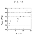
- Fig. 13 the relationship between the iron loss in the finished steel sheet and the P ⁇ 111 ⁇ is shown. As shown in Fig. 13, the iron loss in the finished steel sheet and the P ⁇ 111 ⁇ had a close relationship. In particular, it was discovered that, when the P ⁇ 111 ⁇ was 20% or less, a superior ion loss (W 15/50 ⁇ 2.20 W/kg) could be obtained. The reason for this is believed to be that, since the permissible range was relatively broader, such as 15° for P ⁇ 111 ⁇ calculation, the result was obtained by including contributions from the magnetic properties of other than ⁇ 111 ⁇ , such as ⁇ 544 ⁇ , ⁇ 554 ⁇ , ⁇ 221 ⁇ , and ⁇ 332 ⁇ .
- a steel ingot was formed in which 2.6 percent by weight of Si, 0.13 percent by weight of Mn, and 0.009 percent by weight of Al were contained, and C, S, N, O, and B were respectively reduced to be 20 ppm or less.
- the ingot was heated to 1,050°C and was hot-rolled so as to be 2.6 mm thick.
- the hot-rolled sheet was annealed at 1,150°C for 3 minutes and was then pickled. Subsequently, the annealed sheet was cold-rolled at various temperatures between room temperature and 400°C so as to have a final thickness of 0.35 mm.
- the cold-rolled sheet was annealed for recrystallization at 1,050°C for 10 minutes, thereby obtaining a finished steel sheet.
- Epstein samples of 30 mm in width and 280 mm in length were cut in the L direction and the C direction, and the average magnetic flux densities and iron losses in the L direction and the C direction for the samples were measured.
- Crystal grain orientations of the finished steel sheet were measured by an EBSP for approximately 2,000 crystal grains in an area 10 mm by 10 mm on the surface of the steel sheet, and P ⁇ 111 ⁇ was then obtained.
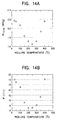
- Figs. 14A and 14B the relationship between the rolling temperature and the iron loss and the relationship between the rolling temperature and the P ⁇ 111 ⁇ are shown, respectively.
- the rolling temperature was controlled in the range from 150 to 350°C, the P ⁇ 111 ⁇ was smaller value, whereby a superior iron loss could be obtained.
- Figs. 15A and 15B the relationship between the average grain diameter after annealing for a hot-rolled sheet and the iron loss, and the relationship between the average grain diameter after annealing for a hot-rolled sheet and the P ⁇ 111 ⁇ are shown, respectively.
- the average grain diameter after annealing for a hot-rolled sheet i.e., the average grain diameter before final cold rolling
- the P ⁇ 111 ⁇ was significantly decreased, whereby the iron loss properties could be further improved.
- Si As a component of the magnetic steel sheet of the present invention, Si must be contained so as to increase electric resistance and to decrease iron loss. In order to satisfy the requirements mentioned above, Si must be contained in an amount of at least 1.5 weight%. On the other hand, when the Si content exceeds 8.0 weight%, the magnetic flux density is decreased, and workability of the finished steel sheet in fabrication is significantly degraded. Accordingly, the content of Si is set to be from 1.5 to 8.0 weight%.
- Mn is an essential component to improve hot-workability. The effect thereof is slight when the content of Mn is less than 0.005 weight%. On the other hand, when the content thereof exceeds 2.50 weight%, the saturation flux density is decreased. Hence, the content of Mn is set to be from 0.005 to 2.50 weight%.
- the average diameter of crystal grains in the finished steel sheet is preferably set to be from 50 to 500 ⁇ m.
- the average diameter of crystal grains is less than 50 ⁇ m, the hysteresis loss is increased. Accordingly, even if the present invention is applied thereto, an increase of iron loss cannot be avoided. In addition, since hardness is increased, workability is also degraded.
- the average diameter exceeds 500 ⁇ m, eddy-current loss is significantly increased. As a result, an increase in iron loss cannot be avoided even if the present invention is applied thereto.
- P ⁇ 111 ⁇ be set to be 20% or less.
- the magnetic flux density of the finished steel sheet is significantly decreased and the iron loss thereof is also significantly increased.
- the Vickers hardness be 240 or less.
- various methods may be considered; however, it is advantageous to primarily control the content of Si, Al, Mn, or the like.
- the content of Si is set to be from 1.5 to 8.0 weight%, and the content of Mn is set to be from 0.005 to 2.50 weight%. The reason for this is the same as previously described.
- the individual maximum contents of C, S, N, O, and B must be set to be 50 ppm, and preferably, set to be 20 ppm.
- Concerning C the content thereof must be 50 ppm or less at least prior to annealing for recrystallization.
- the content may be set to be 50 ppm or less in a composition of a molten steel; alternatively, even if the content exceeds 50 ppm in the composition thereof, the content thereof may be reduced to be 50 ppm or less by a decarburization treatment in a subsequent step.
- the individual contents of the impurities exceed 50 ppm, the ⁇ after annealing for recrystallization is increased, and hence, the magnetic properties are degraded. The reason for this is believed to be that selective grain boundary migration is inhibited.
- Control of Al content is the most effective technique to obtain a non-oriented magnetic steel sheet having the ⁇ of 0.200 or less according to the present invention.
- the Al content is preferably set to be from 0.0010 to 0.10 weight%.
- the Al content exceeds 0.10 weight%, the texture varies, the ⁇ of the finished steel sheet is increased, and hence, the iron loss is increased, and the magnetic flux density is decreased.
- the Al content is less than 0.0010 weight%, silicon nitride is precipitated, and deformation behavior during rolling is influenced.
- the texture varies, and hence, the ⁇ is increased to some extent, whereby the effect of a decrease in ⁇ by reduction of impurities, C, S, N, O, and B was lessened. Accordingly, when the Al content is set to be 0.0010 weight% or more, it is advantageous to improve iron loss and magnetic flux density.
- annealing is performed in the temperature range from 800 to 1,200°C, and subsequently, cooling from 800 to 400°C is performed at a rate of from 5 to 80°C/second.
- an annealing temperature for a hot-rolled sheet is less than 800°C, recrystallization of the hot-rolled sheet insufficiently occurs, and the magnetic properties are also insufficiently improved.
- an annealing temperature for a hot-rolled sheet is more than 1,200°C, the diameters of crystal grains of the hot-rolled sheet are significantly increased, and cracks therein occur during cold rolling. Accordingly, an annealing temperature for a hot-rolled sheet is preferably set to be from 800 to 1,200°C. Concerning a cooling rate, it is preferably controlled as previously described.
- the behavior of recrystallized nuclei growth can be changed. Consequently, ⁇ of the finished steel sheet can be reduced, and hence, superior magnetic properties can be obtained.
- the content of Sb is less than 0.01 weight%, improvement in texture cannot be observed.
- the content of Sb is more than 0.50 weight%, the steel sheet tends to be brittle, and hence, cold rolling is difficult to perform. Accordingly, the content of Sb is preferably set to be from 0.01 to 0.50 weight%.
- a rate of increase in temperature in the range of from 700°C and above is set to be slow, such as 100°C/hour or less, and when the temperature is increased to a maximum temperature between from 750 to 1,200°C, it is advantageous to facilitate grain growth and to improve magnetic properties.
- a rate of increase in temperature in the range of from 700°C and above is more than 100°C/hour, the effect of improving texture is decreased.
- the rate of increase in temperature is preferably set to be from 100°C/hour or less.
- The: minimum rate of increase in temperature is not specifically limited: however, when it is less than 1°C/hour, annealing time is considerably increased, and hence, it is not advantageous from an economic point of view.
- the maximum temperature in annealing for recrystallization is less than 750°C, magnetic properties are degraded due to insufficient grain growth.
- the maximum temperature in annealing for recrystallization is preferably set to be from 750 to 1,200°C.
- the soaking time is not specified. However, in order to obtain a superior iron loss, a longer soaking, which is allowed from an economic point of view, is effective to facilitate grain growth.
- the temperature is rapidly increased at 2°C/second or more from 500 to 700°C, and recrystallization is completed at 700°C or above, and in a second half of annealing for recrystallization, after the temperature is decreased to 700°C or less, it is again slowly increased at 100°C/hour or less in the range of from 700°C and above to 750 to 1,200°C.
- a temperature is preferably increased from 500 to 700°C at 2°C/second or more in the first half of annealing for recrystallization.
- the maximum temperature in the first half of annealing is less than 750°C or more than 1,200°C, an effect of facilitating recrystallization in the second half of annealing is decreased.
- the maximum temperature is preferably from 750 to 1,200°C in the first half of annealing for recrystallization.
- a rate of increase in temperature is preferably set to be 100°C/hour or less in the second half of annealing for recrystallization.
- the maximum temperature in the second half of annealing is less than 750°C, grain growth is insufficient, and when it is more than 1,200°C, oxidation at surfaces occurs, whereby, in both cases, magnetic properties are degraded.
- the maximum temperature is preferably from 750 to 1,200°C in the second half of annealing for recrystallization.
- the soaking time in the second half of annealing is not specified. However, in order to obtain a superior iron loss, a longer soaking, which is allowed from an economic point of view, is effective to facilitate grain growth.
- Cooling conditions are not specifically limited from the point of view of magnetic properties. However, from an economic point of view, the cooling rate is advantageously set to be from 60°C/minute to 10°C/hour.
- Ni may be added.
- the content of Ni is less than 0.01 weight%, improvement in magnetic flux density is not significant.
- the content of Ni is preferably set to be from 0.01 to 1.50 weight%.
- an ingot having the composition according to the present invention may be formed into slabs by common casting or by continuous casting or may be formed into thin steel sheets having a thickness of 100 mm or less by direct casting.
- the slab is heated by a common method and is then hot-rolled.
- the slab may be hot-rolled immediately after casting.
- it may be hot-rolled, or may be transferred to the following step by omitting hot rolling.
- annealing for a hot-rolled sheet is performed, and cold rolling is performed at least one time with, if necessary, interim annealing between steps of cold rolling.
- annealing for recrystallization is performed, and when necessary, coating for insulation is performed.
- an insulating coating is applied to the surface of the steel sheet.
- Coating material may be a multilayer film composed of at least two films or may be mixed with resins or the like.
- an average crystal grain diameter be set to be 100 ⁇ m or more prior to final cold rolling, and that the rolling temperature in at least one pass during final cold rolling be from 150 to 350°C.
- a method for making an average crystal grain diameter prior to cold rolling to be 100 ⁇ m or more a method may be mentioned in which annealing for a hot-rolled sheet or interim annealing is performed at a high temperature such as 1,000°C or more or a method in which cold rolling with the reduction of thickness of from 3 to 7% is performed prior to annealing for a hot-rolled sheet.
- a slab was formed by continuous casting, which was composed 38 ppm C, 3.24 weight% Si, 0.15 weight% Mn, 0.013 weight% Al, 0.02 weight% Sb, 11 ppm S, 7 ppm O, 9 ppm N, 2 ppm B, and substantial iron as the balance.
- the slab was heated to 1,150°C for 30 minutes and was formed into a steel sheet 2.9 mm thick by hot rolling.
- the hot-rolled sheet was annealed at 1,050°C for 60 seconds and was then cooled from 800°C to 400°C at 8°C/second. The annealed sheet was cold-rolled, so that a steel sheet having a final thickness of 0.35 mm was formed.
- annealing for recrystallization was performed in a hydrogen atmosphere in which a temperature was increased at a predetermined rate to a predetermined maximum temperature, both of which are respectively shown in Table 2, and the temperature was then decreased.
- the annealed steel sheet was coated with an inorganic coating solution and was then baked at 300°C, thereby yielding a finished steel sheet.
- a thin cast steel sheet 4.5 mm thick having same compositions of Example 2 was formed by direct casting.
- the thin cast steel sheet was annealed at 1,150°C for 30 seconds and was then cooled from 800°C to 400°C at 50°C/second.
- the annealed sheet was cold-rolled at room temperature, so that a cold-rolled steel sheet 1.6 mm thick was formed.
- the cold-rolled steel sheet was processed by interim annealing at 1,000°C for 60 seconds and was then cold-rolled at room temperature, so that a cold-rolled steel sheet 0.20 mm thick was formed.
- the cold-rolled sheet thus formed was processed in an argon atmosphere by a first and a second annealing for recrystallization under the conditions shown in Table 3, thereby yielding finished steel sheets.
- Annealing hot-rolled sheet Annealing cold-rolled sheet ⁇ Iron loss W 15/50 (w/kg) Magnetic flux density B 50 (T) Rate of increase in temperature (500°C - 700°C) (°C/S) Maximum temperature (°C) Rate of increase in temperature (more than 700°C) (°C/h) Maximum temperature (°C) C1 20 900 20 900 0.150 1.55 1.760 C2 40 900 25 950 0.154 1.56 1.752 C3 10 800 25 1000 0.161 1.59 1.740 C4 20 1000 11 880 0.150 1.50 1.758 C5 5 780 30 1050 0.152 1.61 1.749 C6 1 800 25 900 0.170 1.80 1.731 C7 20 650 25 900 0.171 1.82 1.728 C8 20 900 200 900 0.170 1.85 1.726 C9 20 900 15 700 0.173 1.91 1.720 C10 20 900 40 1250 0.164 2.25 1.735
- the slabs were heated to 1,200°C for 50 minutes and were formed into steel sheets 2.6 mm thick by hot rolling.
- the hot-rolled sheets were annealed at 1,180°C for 120 seconds and were then cooled from 800°C to 400°C at 30°C/second.
- the annealed sheets were cold-rolled at 150°C, so that steel sheets having a final thickness of 0.35 mm were formed.
- annealing for recrystallization was performed at 1,150°C for 1 minute in an argon atmosphere, and a semi-organic coating solution was coated thereon and was then baked at 300°C, thereby yielding finished steel sheets.
- Steel slabs having compositions shown in Table 5 were formed by continuous casting.
- the slabs were heated to 1,150°C for 20 minutes and were formed into steel sheets 2.8 mm thick by hot rolling.
- the hot-rolled sheets were annealed at 1,150°C for 60 seconds.
- the annealed sheets were cold-rolled at 270°C, so that steel sheets having a final thickness of 0.35 mm were formed.
- annealing for recrystallization was performed at 1,050°C for 2 minutes in a hydrogen atmosphere, and a semi-organic coating solution was coated thereon and was then baked at 300°C, thereby yielding finished steel sheets.
- the magnetic properties (average in the L direction and the C direction) of the finished steel sheets were measured. Orientations of the crystal grains in an area 10 mm by 10 mm on the surface of each finished steel sheet were measured by an EBSP, and the ⁇ and P ⁇ 111 ⁇ , the areal ratio of crystal grains on the surface of the steel sheet were then calculated, in which the crystal plane orientations of the crystal grains were within 15° from the ⁇ 111 ⁇ axis.
- each finished steel sheet was also evaluated. Concerning workability, the finished sheets were laminated so as to be approximately 10 mm thick, and 100 holes 30 mm in diameter were formed in the laminate by using a plunger-type punching apparatus, so that workability was determined by the rate of crack occurrence.
- a slab was formed by continuous casting, which was composed of 38 ppm C, 3.74 wt% Si, 0.35 wt% Mn, 0.013 wt% Al, 11 ppm S, 7 ppm O, 9 ppm N, and substantial iron as the balance.
- the slab was heated to 1,100°C for 20 minutes and was formed into steel sheet 3.2 mm thick by hot rolling.
- the hot-rolled steel sheet was annealed at a temperature shown in Table 6 for 60 seconds.
- the annealed steel sheet was cold-rolled at a temperature shown in Table 6, so that a steel sheet having a final thickness of 0.50 mm was formed.
- annealing for recrystallization was performed at a temperature shown in Table 6 for 120 seconds, and the annealed sheet was coated with an inorganic coating solution and was then baked at 300°C, thereby yielding a finished steel sheet.
- finished steel sheet had particularly superior magnetic properties and superior workability when the grain diameter thereof before cold rolling was increased, and the temperature for cold rolling was increased.
- Thin cast steel sheets 4,5 mm thick having compositions shown in Table 7 were formed by direct casting.
- the thin cast steel sheets were annealed at 1,150°C for 60 seconds and were then cold-rolled at room temperature, so that cold-rolled steel sheets having an interim thickness of 1.2 mm were formed.
- the cold-rolled steel sheets were processed by interim annealing at 1,000°C for 60 seconds and were then cold-rolled at room temperature, so that cold-rolled steel sheets having a final thickness of 0.35 mm were formed.
- the cold-rolled sheets thus formed were processed in an argon atmosphere by annealing for recrystallization at 1,025°C for 5 minutes, thereby yielding finished steel sheets.
- the finished steel sheets had superior magnetic properties and superior workability.
Landscapes
- Engineering & Computer Science (AREA)
- Chemical & Material Sciences (AREA)
- Physics & Mathematics (AREA)
- Electromagnetism (AREA)
- Mechanical Engineering (AREA)
- Manufacturing & Machinery (AREA)
- Thermal Sciences (AREA)
- Crystallography & Structural Chemistry (AREA)
- Materials Engineering (AREA)
- Metallurgy (AREA)
- Organic Chemistry (AREA)
- Power Engineering (AREA)
- Dispersion Chemistry (AREA)
- Manufacturing Of Steel Electrode Plates (AREA)
- Soft Magnetic Materials (AREA)
Priority Applications (1)
| Application Number | Priority Date | Filing Date | Title |
|---|---|---|---|
| EP10011680A EP2287347B1 (de) | 1999-09-03 | 2000-08-30 | Nicht-kornorientiertes Elektrostahlblech mit niedrigen Wattverlusten und hoher Magnetflussdichte und Verfahren zu seiner Herstellung |
Applications Claiming Priority (4)
| Application Number | Priority Date | Filing Date | Title |
|---|---|---|---|
| JP24971899A JP3855554B2 (ja) | 1999-09-03 | 1999-09-03 | 無方向性電磁鋼板の製造方法 |
| JP24971899 | 1999-09-03 | ||
| JP2000058130A JP4240736B2 (ja) | 2000-03-03 | 2000-03-03 | 鉄損が低くかつ磁束密度が高い無方向性電磁鋼板およびその製造方法 |
| JP2000058130 | 2000-03-03 |
Related Child Applications (2)
| Application Number | Title | Priority Date | Filing Date |
|---|---|---|---|
| EP10011680A Division EP2287347B1 (de) | 1999-09-03 | 2000-08-30 | Nicht-kornorientiertes Elektrostahlblech mit niedrigen Wattverlusten und hoher Magnetflussdichte und Verfahren zu seiner Herstellung |
| EP10011680.5 Division-Into | 2010-09-29 |
Publications (3)
| Publication Number | Publication Date |
|---|---|
| EP1081238A2 true EP1081238A2 (de) | 2001-03-07 |
| EP1081238A3 EP1081238A3 (de) | 2003-07-02 |
| EP1081238B1 EP1081238B1 (de) | 2011-04-06 |
Family
ID=26539439
Family Applications (2)
| Application Number | Title | Priority Date | Filing Date |
|---|---|---|---|
| EP00118794A Expired - Lifetime EP1081238B1 (de) | 1999-09-03 | 2000-08-30 | Nicht-kornorientiertes Elektrostahlblech mit niedrigen Wattverlusten und hoher Magnetflussdichte |
| EP10011680A Expired - Lifetime EP2287347B1 (de) | 1999-09-03 | 2000-08-30 | Nicht-kornorientiertes Elektrostahlblech mit niedrigen Wattverlusten und hoher Magnetflussdichte und Verfahren zu seiner Herstellung |
Family Applications After (1)
| Application Number | Title | Priority Date | Filing Date |
|---|---|---|---|
| EP10011680A Expired - Lifetime EP2287347B1 (de) | 1999-09-03 | 2000-08-30 | Nicht-kornorientiertes Elektrostahlblech mit niedrigen Wattverlusten und hoher Magnetflussdichte und Verfahren zu seiner Herstellung |
Country Status (5)
| Country | Link |
|---|---|
| US (2) | US6436199B1 (de) |
| EP (2) | EP1081238B1 (de) |
| KR (1) | KR100702875B1 (de) |
| CN (1) | CN1138014C (de) |
| DE (1) | DE60045810D1 (de) |
Cited By (6)
| Publication number | Priority date | Publication date | Assignee | Title |
|---|---|---|---|---|
| EP1310576A4 (de) * | 2000-06-30 | 2005-06-29 | Jfe Steel Corp | Stahlblech für wärmeschrumpffähiges band |
| EP1580289A4 (de) * | 2002-12-05 | 2006-02-01 | Jfe Steel Corp | Nichtkornorientiertes magnetisches stahlblech und herstellungsverfahren dafür |
| EP2883975A4 (de) * | 2012-08-08 | 2015-11-18 | Jfe Steel Corp | Hochfestes elektromagnetisches stahlblech und verfahren zu seiner herstellung |
| EP3572545A4 (de) * | 2017-01-17 | 2019-12-11 | JFE Steel Corporation | Nichtorientiertes elektromagnetisches stahlblech und herstellungsverfahren dafür |
| US11866797B2 (en) | 2018-11-02 | 2024-01-09 | Nippon Steel Corporation | Non-oriented electrical steel sheet |
| EP4490330A4 (de) * | 2022-03-18 | 2025-07-16 | Nucor Corp | Elektrische stähle |
Families Citing this family (28)
| Publication number | Priority date | Publication date | Assignee | Title |
|---|---|---|---|---|
| US6599290B2 (en) * | 2001-04-17 | 2003-07-29 | Ebi, L.P. | Anterior cervical plating system and associated method |
| WO2003002777A1 (fr) * | 2001-06-28 | 2003-01-09 | Jfe Steel Corporation | Feuille en acier electromagnetique non orientee |
| DE10220282C1 (de) * | 2002-05-07 | 2003-11-27 | Thyssenkrupp Electrical Steel Ebg Gmbh | Verfahren zum Herstellen von kaltgewalztem Stahlband mit Si-Gehalten von mindestens 3,2 Gew.-% für elektromagnetische Anwendungen |
| CN100557057C (zh) * | 2004-04-16 | 2009-11-04 | 新日本制铁株式会社 | 冲裁加工性和消除应力退火后的磁特性优良的无方向性电磁钢板及其制造方法 |
| JP4817418B2 (ja) * | 2005-01-31 | 2011-11-16 | オンセミコンダクター・トレーディング・リミテッド | 回路装置の製造方法 |
| JP2007314826A (ja) * | 2006-05-24 | 2007-12-06 | Nippon Steel Corp | 鉄損特性に優れた一方向性電磁鋼板 |
| JP4648910B2 (ja) * | 2006-10-23 | 2011-03-09 | 新日本製鐵株式会社 | 磁気特性の優れた無方向性電磁鋼板の製造方法 |
| CN101967602B (zh) * | 2010-10-19 | 2012-08-08 | 东北大学 | 一种无取向硅钢薄带及其制备方法 |
| JP5733409B2 (ja) * | 2011-09-27 | 2015-06-10 | Jfeスチール株式会社 | 無方向性電磁鋼板 |
| CN104039998B (zh) | 2011-12-28 | 2017-10-24 | Posco公司 | 无取向电工钢板及其制造方法 |
| JP6127408B2 (ja) | 2012-08-17 | 2017-05-17 | Jfeスチール株式会社 | 無方向性電磁鋼板の製造方法 |
| JP5533958B2 (ja) * | 2012-08-21 | 2014-06-25 | Jfeスチール株式会社 | 打抜加工による鉄損劣化の小さい無方向性電磁鋼板 |
| US20190024205A9 (en) * | 2015-10-02 | 2019-01-24 | Jfe Steel Corporation | Non-oriented electrical steel sheet and method of producing same |
| JP6451873B2 (ja) | 2016-10-27 | 2019-01-16 | Jfeスチール株式会社 | 無方向性電磁鋼板およびその製造方法 |
| CN107011795B (zh) * | 2017-05-12 | 2018-10-19 | 沙河市湡久新材料有限公司 | 硅烷系粘合剂成分在无溶剂涂料中的应用方法 |
| WO2018213556A1 (en) * | 2017-05-17 | 2018-11-22 | Crs Holdings, Inc. | Fe-si base alloy and method of making same |
| CN106987776B (zh) * | 2017-06-02 | 2018-10-26 | 郑州永通特钢有限公司 | 一种镍铬磷系高性能无取向电工钢 |
| DE102018201622A1 (de) * | 2018-02-02 | 2019-08-08 | Thyssenkrupp Ag | Nachglühfähiges, aber nicht nachglühpflichtiges Elektroband |
| CN113646449B (zh) * | 2019-04-03 | 2023-06-20 | 日本制铁株式会社 | 电磁钢板及其制造方法 |
| KR102635010B1 (ko) * | 2019-07-11 | 2024-02-07 | 제이에프이 스틸 가부시키가이샤 | 무방향성 전기 강판과 그 제조 방법 및 모터 코어 |
| CN110760736A (zh) * | 2019-11-11 | 2020-02-07 | 徐灿华 | 一种新型纳米结晶磁性材料的制备方法 |
| US12173379B2 (en) | 2019-11-12 | 2024-12-24 | Lg Electronics Inc. | Non-oriented electrical steel sheet and manufacturing method therefore |
| KR102825338B1 (ko) * | 2019-11-12 | 2025-06-27 | 엘지전자 주식회사 | 무방향성 전기강판 및 그 제조 방법 |
| US20230104017A1 (en) * | 2020-04-02 | 2023-04-06 | Nippon Steel Corporation | Non-oriented electrical steel sheet and method of manufacturing the same |
| CN116888295B (zh) * | 2021-03-31 | 2024-03-19 | 日本制铁株式会社 | 无取向性电磁钢板、电机铁芯、无取向性电磁钢板的制造方法及电机铁芯的制造方法 |
| KR20240165997A (ko) * | 2022-03-30 | 2024-11-25 | 닛폰세이테츠 가부시키가이샤 | 무방향성 전자 강판 및 모터 코어 |
| CN115418440B (zh) * | 2022-07-29 | 2023-07-28 | 新疆八一钢铁股份有限公司 | 一种高强度冷轧板的制备方法 |
| KR20240075044A (ko) * | 2022-11-18 | 2024-05-29 | 주식회사 포스코 | 무방향성 전기강판 및 그 제조방법 |
Citations (2)
| Publication number | Priority date | Publication date | Assignee | Title |
|---|---|---|---|---|
| JPS5815143A (ja) | 1981-07-22 | 1983-01-28 | Toshiba Corp | 複合金属線の検査方法 |
| JPH03281758A (ja) | 1990-03-29 | 1991-12-12 | Sumitomo Metal Ind Ltd | 高抗張力電磁鋼板およびその製造方法 |
Family Cites Families (14)
| Publication number | Priority date | Publication date | Assignee | Title |
|---|---|---|---|---|
| SE448381B (sv) * | 1978-09-19 | 1987-02-16 | Tsuya Noboru | Sett att framstella ett tunt band av kiselstal, tunt kiselstalband och anvendning av dylikt |
| JPS58151453A (ja) * | 1982-01-27 | 1983-09-08 | Nippon Steel Corp | 鉄損が低くかつ磁束密度のすぐれた無方向性電磁鋼板およびその製造法 |
| JPS63137122A (ja) * | 1986-11-28 | 1988-06-09 | Kawasaki Steel Corp | 磁気特性の優れた無方向性けい素鋼板の製造方法 |
| JPH01225724A (ja) * | 1988-03-04 | 1989-09-08 | Nkk Corp | 低磁場磁気特性の優れた無方向性電磁鋼板の製造方法 |
| JP2717009B2 (ja) * | 1989-09-13 | 1998-02-18 | 川崎製鉄株式会社 | 磁気特性の優れた無方向性電磁鋼板の製造方法 |
| KR950002895B1 (ko) * | 1990-06-20 | 1995-03-28 | 신닛뽄 세이데쓰 가부시끼가이샤 | 초고규소 방향성 전자강판 및 그 제조방법 |
| JP2898793B2 (ja) * | 1991-07-05 | 1999-06-02 | 新日本製鐵株式会社 | 高磁束密度、低鉄損を有する無方向性電磁鋼板の製造方法 |
| KR960011799B1 (ko) * | 1991-08-14 | 1996-08-30 | 신닛뽄 세이데스 가부시기가이샤 | 무방향성 전기 강판의 제조 방법 |
| JPH06240358A (ja) * | 1993-02-12 | 1994-08-30 | Nippon Steel Corp | 磁束密度が高く、鉄損の低い無方向性電磁鋼板の製造方法 |
| JP3575167B2 (ja) * | 1996-05-15 | 2004-10-13 | Jfeスチール株式会社 | 低磁場特性に優れた無方向性電磁鋼板の製造方法 |
| JP3100122B2 (ja) | 1996-07-22 | 2000-10-16 | 住友ゴム工業株式会社 | 空気入りタイヤ |
| JP3352904B2 (ja) * | 1997-03-14 | 2002-12-03 | 新日本製鐵株式会社 | 無方向性電磁鋼板の製造方法 |
| JP3458683B2 (ja) * | 1997-11-28 | 2003-10-20 | Jfeスチール株式会社 | 歪取り焼鈍後の磁気特性に優れる無方向性電磁鋼板の製造方法 |
| JPH11189850A (ja) * | 1997-12-24 | 1999-07-13 | Sumitomo Metal Ind Ltd | 無方向性電磁鋼板およびその製造方法 |
-
2000
- 2000-08-29 US US09/649,052 patent/US6436199B1/en not_active Expired - Lifetime
- 2000-08-30 EP EP00118794A patent/EP1081238B1/de not_active Expired - Lifetime
- 2000-08-30 DE DE60045810T patent/DE60045810D1/de not_active Expired - Lifetime
- 2000-08-30 EP EP10011680A patent/EP2287347B1/de not_active Expired - Lifetime
- 2000-09-01 CN CNB001338420A patent/CN1138014C/zh not_active Expired - Lifetime
- 2000-09-01 KR KR1020000051446A patent/KR100702875B1/ko not_active Expired - Fee Related
-
2002
- 2002-05-08 US US10/140,207 patent/US6531001B2/en not_active Expired - Lifetime
Patent Citations (2)
| Publication number | Priority date | Publication date | Assignee | Title |
|---|---|---|---|---|
| JPS5815143A (ja) | 1981-07-22 | 1983-01-28 | Toshiba Corp | 複合金属線の検査方法 |
| JPH03281758A (ja) | 1990-03-29 | 1991-12-12 | Sumitomo Metal Ind Ltd | 高抗張力電磁鋼板およびその製造方法 |
Cited By (10)
| Publication number | Priority date | Publication date | Assignee | Title |
|---|---|---|---|---|
| EP1310576A4 (de) * | 2000-06-30 | 2005-06-29 | Jfe Steel Corp | Stahlblech für wärmeschrumpffähiges band |
| EP1580289A4 (de) * | 2002-12-05 | 2006-02-01 | Jfe Steel Corp | Nichtkornorientiertes magnetisches stahlblech und herstellungsverfahren dafür |
| US7513959B2 (en) | 2002-12-05 | 2009-04-07 | Jfe Steel Corporation | Non-oriented electrical steel sheet and method for manufacturing the same |
| EP2489753A1 (de) * | 2002-12-05 | 2012-08-22 | JFE Steel Corporation | Nichtausgerichtetes magnetisches Stahlblech und Herstellungsverfahren dafür |
| EP2883975A4 (de) * | 2012-08-08 | 2015-11-18 | Jfe Steel Corp | Hochfestes elektromagnetisches stahlblech und verfahren zu seiner herstellung |
| US10242782B2 (en) | 2012-08-08 | 2019-03-26 | Jfe Steel Corporation | High-strength electrical steel sheet and method of producing the same |
| EP3572545A4 (de) * | 2017-01-17 | 2019-12-11 | JFE Steel Corporation | Nichtorientiertes elektromagnetisches stahlblech und herstellungsverfahren dafür |
| US11286537B2 (en) | 2017-01-17 | 2022-03-29 | Jfe Steel Corporation | Non-oriented electrical steel sheet and method of producing same |
| US11866797B2 (en) | 2018-11-02 | 2024-01-09 | Nippon Steel Corporation | Non-oriented electrical steel sheet |
| EP4490330A4 (de) * | 2022-03-18 | 2025-07-16 | Nucor Corp | Elektrische stähle |
Also Published As
| Publication number | Publication date |
|---|---|
| EP1081238A3 (de) | 2003-07-02 |
| DE60045810D1 (de) | 2011-05-19 |
| EP2287347A1 (de) | 2011-02-23 |
| US6531001B2 (en) | 2003-03-11 |
| US20030024606A1 (en) | 2003-02-06 |
| CN1305019A (zh) | 2001-07-25 |
| EP2287347B1 (de) | 2012-10-10 |
| KR100702875B1 (ko) | 2007-04-04 |
| EP1081238B1 (de) | 2011-04-06 |
| CN1138014C (zh) | 2004-02-11 |
| KR20010030210A (ko) | 2001-04-16 |
| US6436199B1 (en) | 2002-08-20 |
Similar Documents
| Publication | Publication Date | Title |
|---|---|---|
| US6436199B1 (en) | Non-oriented magnetic steel sheet having low iron loss and high magnetic flux density and manufacturing method therefor | |
| RU2318883C2 (ru) | Способ непрерывного литья полосы неориентированной электротехнической стали | |
| US6562473B1 (en) | Electrical steel sheet suitable for compact iron core and manufacturing method therefor | |
| CA1333988C (en) | Ultra-rapid annealing of nonoriented electrical steel | |
| JP7667490B2 (ja) | 無方向性電磁鋼板およびその製造方法 | |
| JP4218077B2 (ja) | 無方向性電磁鋼板およびその製造方法 | |
| EP4400622A1 (de) | Nichtorientiertes elektrostahlblech und verfahren zur herstellung davon sowie verfahren zur herstellung von motorkernen | |
| CA2459479C (en) | Method of producing (110)[001] grain oriented electrical steel using strip casting | |
| JP4075083B2 (ja) | 方向性電磁鋼板の製造方法 | |
| CN114341383A (zh) | 无方向性电磁钢板的制造方法 | |
| JP4276391B2 (ja) | 高級無方向性電磁鋼板 | |
| JP3551849B2 (ja) | 一方向性電磁鋼板用の一次再結晶焼鈍板 | |
| JP3896937B2 (ja) | 方向性電磁鋼板の製造方法 | |
| US5913987A (en) | Finish treatment method and silicon steel sheet manufactured by direct casting method | |
| JP2560579B2 (ja) | 高透磁率を有する高珪素鋼板の製造方法 | |
| JP7415136B2 (ja) | 無方向性電磁鋼板の製造方法 | |
| WO2022210955A1 (ja) | 回転電機、ステータの鉄心およびロータの鉄心のセット、回転電機の製造方法、無方向性電磁鋼板の製造方法、回転電機のロータおよびステータの製造方法並びに無方向性電磁鋼板のセット | |
| JP4013262B2 (ja) | 無方向性電磁鋼板およびその製造方法 | |
| TWI909306B (zh) | 無方向性電磁鋼板 | |
| JPS6184326A (ja) | 鉄損の優れた薄手高磁束密度一方向性電磁鋼板の製造方法 | |
| JPH0657332A (ja) | 磁束密度が高くかつ鉄損が低い無方向性電磁鋼板の製造方法 | |
| JP2599529B2 (ja) | 磁気特性の優れた無方向性電磁鋼板の製造方法 | |
| EP4650473A1 (de) | Nichtorientiertes elektromagnetisches stahlblech | |
| JPH0737651B2 (ja) | 磁気特性の優れた無方向性電磁鋼板の製造方法 | |
| JP2000178699A (ja) | 磁束密度が高く加工性に優れた高珪素鋼板 |
Legal Events
| Date | Code | Title | Description |
|---|---|---|---|
| PUAI | Public reference made under article 153(3) epc to a published international application that has entered the european phase |
Free format text: ORIGINAL CODE: 0009012 |
|
| AK | Designated contracting states |
Kind code of ref document: A2 Designated state(s): AT BE CH CY DE DK ES FI FR GB GR IE IT LI LU MC NL PT SE |
|
| AX | Request for extension of the european patent |
Free format text: AL;LT;LV;MK;RO;SI |
|
| PUAL | Search report despatched |
Free format text: ORIGINAL CODE: 0009013 |
|
| AK | Designated contracting states |
Designated state(s): AT BE CH CY DE DK ES FI FR GB GR IE IT LI LU MC NL PT SE |
|
| AX | Request for extension of the european patent |
Extension state: AL LT LV MK RO SI |
|
| RIC1 | Information provided on ipc code assigned before grant |
Ipc: 7H 01F 1/147 B Ipc: 7H 01F 1/16 B Ipc: 7C 21D 8/12 A |
|
| RAP1 | Party data changed (applicant data changed or rights of an application transferred) |
Owner name: JFE STEEL CORPORATION |
|
| 17P | Request for examination filed |
Effective date: 20031117 |
|
| AKX | Designation fees paid |
Designated state(s): DE FR GB IT SE |
|
| 17Q | First examination report despatched |
Effective date: 20080530 |
|
| GRAP | Despatch of communication of intention to grant a patent |
Free format text: ORIGINAL CODE: EPIDOSNIGR1 |
|
| RTI1 | Title (correction) |
Free format text: NON-ORIENTED MAGNETIC STEEL SHEET HAVING LOW IRON LOSS AND HIGH MAGNETIC FLUX DENSITY |
|
| GRAS | Grant fee paid |
Free format text: ORIGINAL CODE: EPIDOSNIGR3 |
|
| GRAA | (expected) grant |
Free format text: ORIGINAL CODE: 0009210 |
|
| AK | Designated contracting states |
Kind code of ref document: B1 Designated state(s): DE FR GB IT SE |
|
| REG | Reference to a national code |
Ref country code: GB Ref legal event code: FG4D |
|
| REF | Corresponds to: |
Ref document number: 60045810 Country of ref document: DE Date of ref document: 20110519 Kind code of ref document: P |
|
| REG | Reference to a national code |
Ref country code: DE Ref legal event code: R096 Ref document number: 60045810 Country of ref document: DE Effective date: 20110519 |
|
| REG | Reference to a national code |
Ref country code: SE Ref legal event code: TRGR |
|
| PLBE | No opposition filed within time limit |
Free format text: ORIGINAL CODE: 0009261 |
|
| STAA | Information on the status of an ep patent application or granted ep patent |
Free format text: STATUS: NO OPPOSITION FILED WITHIN TIME LIMIT |
|
| 26N | No opposition filed |
Effective date: 20120110 |
|
| REG | Reference to a national code |
Ref country code: DE Ref legal event code: R097 Ref document number: 60045810 Country of ref document: DE Effective date: 20120110 |
|
| REG | Reference to a national code |
Ref country code: FR Ref legal event code: PLFP Year of fee payment: 17 |
|
| REG | Reference to a national code |
Ref country code: FR Ref legal event code: PLFP Year of fee payment: 18 |
|
| REG | Reference to a national code |
Ref country code: FR Ref legal event code: PLFP Year of fee payment: 19 |
|
| PGFP | Annual fee paid to national office [announced via postgrant information from national office to epo] |
Ref country code: DE Payment date: 20190820 Year of fee payment: 20 Ref country code: IT Payment date: 20190821 Year of fee payment: 20 Ref country code: SE Payment date: 20190813 Year of fee payment: 20 Ref country code: FR Payment date: 20190711 Year of fee payment: 20 |
|
| PGFP | Annual fee paid to national office [announced via postgrant information from national office to epo] |
Ref country code: GB Payment date: 20190830 Year of fee payment: 20 |
|
| REG | Reference to a national code |
Ref country code: DE Ref legal event code: R071 Ref document number: 60045810 Country of ref document: DE |
|
| REG | Reference to a national code |
Ref country code: GB Ref legal event code: PE20 Expiry date: 20200829 |
|
| REG | Reference to a national code |
Ref country code: SE Ref legal event code: EUG |
|
| PG25 | Lapsed in a contracting state [announced via postgrant information from national office to epo] |
Ref country code: GB Free format text: LAPSE BECAUSE OF EXPIRATION OF PROTECTION Effective date: 20200829 |