EP1081266A2 - Verfahren und Vorrichtung zum Nassbehandeln, insbesondere Waschen, von Wäschestücken - Google Patents
Verfahren und Vorrichtung zum Nassbehandeln, insbesondere Waschen, von Wäschestücken Download PDFInfo
- Publication number
- EP1081266A2 EP1081266A2 EP00117242A EP00117242A EP1081266A2 EP 1081266 A2 EP1081266 A2 EP 1081266A2 EP 00117242 A EP00117242 A EP 00117242A EP 00117242 A EP00117242 A EP 00117242A EP 1081266 A2 EP1081266 A2 EP 1081266A2
- Authority
- EP
- European Patent Office
- Prior art keywords
- drum
- chamber
- treatment
- laundry
- chambers
- Prior art date
- Legal status (The legal status is an assumption and is not a legal conclusion. Google has not performed a legal analysis and makes no representation as to the accuracy of the status listed.)
- Granted
Links
Images


Classifications
-
- D—TEXTILES; PAPER
- D06—TREATMENT OF TEXTILES OR THE LIKE; LAUNDERING; FLEXIBLE MATERIALS NOT OTHERWISE PROVIDED FOR
- D06F—LAUNDERING, DRYING, IRONING, PRESSING OR FOLDING TEXTILE ARTICLES
- D06F31/00—Washing installations comprising an assembly of several washing machines or washing units, e.g. continuous flow assemblies
- D06F31/005—Washing installations comprising an assembly of several washing machines or washing units, e.g. continuous flow assemblies consisting of one or more rotating drums through which the laundry passes in a continuous flow
Definitions
- the invention relates to a method for wet treatment, in particular Washing of laundry according to the generic term of Claim 1 or the preamble of claim 15. Furthermore The invention relates to a device for wet treatment, in particular Washing of laundry according to the generic term of Claim 6.
- the invention relates to the wet treatment of laundry with commercial washing machines.
- washing machines have a rotating drivable, elongated drum.
- the Items of laundry are lengthwise through the treatment direction Conveyed through and at least washed and rinsed. If necessary, is carried out after the rinsing Equip the laundry inside the washing machine.
- the treatment especially the washing of the laundry in the washing machine, is done with a treatment liquid, which is usually water for washing or Equip the necessary additives.
- a treatment liquid which is usually water for washing or Equip the necessary additives.
- the treatment liquid flows against this type the treatment direction in counterflow through the drum.
- constant mixing may differ highly contaminated treatment fluids.
- a selective exchange of the treatment liquid or a Loading of the laundry items at a certain treatment stage with a special properties and a certain treatment liquid having a degree of contamination, washing water in particular is known in such Washing machines not possible.
- the object of the invention based on a method and an apparatus for Wet treatment, especially for washing laundry items create what an individual or targeted treatment (Laundry) of the laundry items is possible.
- a procedure for solving this problem shows the measures of Claim 1 on.
- the flow of the Treatment liquid is interrupted or interrupted can be, it is possible in the area concerned Drum to remove the treatment liquid in a targeted manner.
- the Flow of the treatment liquid through the drum, especially against the direction of treatment can therefore in Targeted area of one or more corresponding chambers be interrupted, especially for a specific one Period. It can be done this way with a universal Washing machine without changing the same specific compartments a targeted treatment of the laundry items can be assigned. This allows the treatment zones inside the drum the washing machine, in particular the washing zone and / or the Change rinse zone, if necessary, for example to adapt to Items of laundry that require different treatments.
- the Flow of the treatment liquid through the respective Chamber or several chambers only in a certain one Drum position interrupted.
- the Flow of treatment liquid through the drum in interrupted a position of the same in which the Chamber with items of laundry and if necessary Treatment liquid is loaded and / or unloaded.
- the flow of the treatment liquid through the Drum for other purposes, especially for treatment such as Example washing the laundry, guaranteed.
- Treatment liquid is removed if necessary. It deals preferably the treatment liquid in two mutually facing partial areas of two neighboring Chambers.
- the chambers are in a certain position Drum, i.e. only for a certain period of time, into the sub-areas divided by liquid-tight blades in the relevant chambers. This way it is possible in one defined longitudinal area of the drum, the flow through it temporarily interrupt with treatment liquid, so when draining the treatment liquid from neighboring No other treatment liquid can flow into the chambers.
- the Measures of claim 15 Another method for solving the above Task, which is also a training of the above described method can act, the Measures of claim 15. Accordingly, during the Treatment of the items of laundry the angle of rotation or one to the angle of rotation proportional value of the drum and / or the angular velocity or a proportional value of the drum measured.
- the angle of rotation (or a angle of rotation proportional Value) and the angular velocity (or a value proportional to the angular velocity) of the drum continuously determined the proportional, preferably non-contact measurement of a single value may be sufficient to get the angle of rotation and the angular velocity of the To determine the drum mathematically.
- the determined values can are used to control the treatment of the laundry depending on their type. In particular, the treatment process in this way based on each items to be treated according to individual programs Taxes.
- the method is provided on the items of laundry exercised when starting and braking the drum Acceleration forces depending on the determined Controlling the angular speed of the drum in a targeted manner. This can ensure sensitive items of laundry that during treatment, especially at a periodic one required for a swinging laundry Reversal of the direction of rotation of the drum, not overused become.
- a device for solving the problem mentioned at the beginning has the features of claim 6.
- subdivision the drum in individual chambers it is possible to have a one-piece Creating drums that are driven as a whole can.
- the individual chambers offer the prerequisite for an individual treatment of the laundry items.
- the device liquid-impermeable blades arranged.
- the chambers can be divided if the blades Flow of treatment liquid interrupted by the drum to be, for example, on a particular Place the treatment liquid in the drum, for example dirty washing water, specifically to branch off.
- the blades are preferably designed and in the Chambers arranged that they start from a longitudinal central axis the drum to form a cylinder jacket in the area extend a respective chamber.
- the blades are in place thereby eccentric with respect to the longitudinal central axis of the drum in the same and thus also off-center in the concerned chamber. In this way, the blades interrupt only in a certain position of the drum, if namely the blades are in the bottom of the chamber, the flow through the treatment liquid by the concerned Chamber in the drum.
- the chamber in question are flowed through unhindered by the treatment liquid, if the drum is in a different position, in of the blade at least partially from the treatment liquid emerges.
- the blade is preferably designed in a spiral shape. there extend the outer edges of the spiral blade slanted along the inside of the cylinder jacket through the relevant chamber, namely from a partition to opposite partition. This edge of the spiral Blade is connected to the inner wall of the cylinder jacket, so that between the cylinder jacket and the one in the Treatment liquid immersing scoop no treatment liquid from one side of the bucket to the other can flow.
- each chamber formed by, for example, a perforation. Except of this, however, is such a partial area of the cylinder jacket, which is on one side of the bucket in question, namely preferably in front of a side facing the beginning of the drum the shovel. It prevents treatment liquid from the relevant side of the bucket through the Cylinder jacket through under the associated edge of the Bucket can flow along and through the perforated Cylinder jacket on the opposite side (front) the blade can flow back into the chamber.
- the treatment liquid that is in front of the scoop one chamber and through the liquid-tight in this area Do not drain the section of the cylinder jacket can, through an opening associated with the blade in the partition to the adjacent chamber following in the treatment direction flow where on the front side (back) of the Blade of the next chamber the cylinder jacket is perforated thereby deriving treatment fluid at this point can be. Due to this special partially liquid-permeable Training of the cylinder jacket and the closed Training of the shovel is achieved between two Scooping treatment liquid in successive chambers included and removed if necessary can.
- the partitions between adjacent To form chambers of the drum partially permeable to liquid, by doing this for example over a sub-area their surface is perforated.
- one of the off-center opening for loading and unloading the respective Chamber opposite, preferably semicircular, part liquid-permeable to each partition. It deals is that part of the respective partition that during the treatment of the laundry items in the treatment liquid immersed, then below the longitudinal central axis the drum.
- a liquid-permeable Formation of all partitions between neighboring ones Chambering is a flow through during the treatment of the laundry items the treatment liquid through the chambers and thus an uninterrupted flow through the entire drum guaranteed by the treatment liquid.
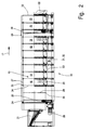
- the device shown here is a Continuous washing machine 10.
- the continuous washing machine 10 4 to 6 are symbolically indicated by squares in FIGS Items 11 washed, rinsed and optionally a subsequent aftertreatment, for example equipment.
- the continuous washing machine 10 has an elongated one Drum 12 rotating about a horizontal longitudinal central axis 13 is drivable, specifically in opposite Directions.
- the drum 12 of the continuous washing machine shown here 10 is divided into different zones, namely one Washing zone 14, a rinsing zone 15 and a finishing zone 16. Die Washing zone 14, rinsing zone 15 and finishing zone 16 are in Treatment direction 17 in succession in the drum 12 of the Continuous washing machine 10 arranged.
- the washing zone 14 and the Rinsing zone 15 are preferably formed from several in the longitudinal direction, thus along the longitudinal central axis 13 of the drum 12, successive washing chambers 18 and rinsing chambers 19.
- Die Number of successive wash chambers 18 and rinse chambers 19 of the washing zone 14 and the rinsing zone 15 can, depending on the size and Performance of the continuous washing machine 10 vary. Accordingly, the invention is not limited to that shown here Embodiment of the continuous washing machine 10 limited.
- the equipment zone 16 has in the device of FIGS. 1 and 2 via two equipment chambers 20. It may be sufficient to provide only one finishing chamber 20 at the end of the drum 12. It is also conceivable that there is no equipment chamber 20 at all Let rinse zone 15 follow. It is also possible if necessary to use the last rinsing chamber 19 as a finishing chamber 20. A such a continuous washing machine 10 then does not have its own and equipment chamber 20 used exclusively for equipment.
- an input funnel 21 In front of the drum 12 of the continuous washing machine is an input funnel 21 provided. About the input funnel 21 can washing laundry items 11 in the washing zone 14 of the continuous washing machine 10 are promoted. At the back of the Continuous washing machine 10 is in the embodiment shown an output chute 22 is provided. Over the dispensing chute can be washed and, if necessary, equipped items of laundry 11 transported out of the continuous washing machine 10 be, if necessary in a subsequent and Drainage device, not shown, for example a Dewatering press.
- the Drum 12 partially surrounded by a liquid-tight one Outer drum 23.
- the outer drum 23 serves to receive Treatment liquid, especially water, if necessary Additives, for example detergents, are added.
- the Outer drum 23 extends only over a portion of the Drum 12.
- the first three chambers of drum 12 and the third to last chamber of drum 12 have here continuous washing machine 10 shown via no outer drum 23 (Fig. 2).
- the front and rear end of the drum 12, to which no outer drum 23 is assigned, are in each case with provided a circumferential race 24.
- the races 24 are supported on rotating impellers 25 all around. Through this
- the drum 12 is supported about its longitudinal central axis 13 rotatable, which thereby simultaneously the axis of rotation of the drum 12th forms.
- At least one impeller 25 can be driven in rotation a drive motor 26. This is preferably an electric motor with a gear. Others can Motors, for example a hydraulic motor, can be used.
- Drum 12 The elongated, rotatable about the horizontal longitudinal central axis 13 Drum 12 is formed in one piece according to the invention.
- the Drum 12 has a cylindrical shape.
- the individual chambers namely wash chambers 18, rinsing chambers 19 and finishing chambers 20.
- All washing chambers 18 and rinsing chambers 19 are exemplary embodiments and equipment chambers 20 of the same size, namely extend over an equal length section of the drum 12.
- Each chamber has a cylinder jacket 27, the one Forms part of the drum 12 and forms in the treatment direction 17 over the entire length or width of the chamber in question extends. Furthermore, the drum 12 has partitions 28 that are evenly spaced vertically to the longitudinal central axis 13 of the drum 12 planes lie. Each chamber is delimited by two parallel partitions 28, the opposite end faces of each Cylinder jacket 27 are assigned. Between two successive ones Cylinder jackets 27 different chambers each have a partition 28 arranged. All partitions 28 are preferably of the same design. The partitions 27 are with the assigned to them end faces of the cylinder jackets 27 of the connected individual chambers, preferably welded thereto.
- the cylinder jackets 27 are included connected to each other by the partitions 28. It is a partition 28 between adjacent cylinder jackets 27 attached.
- the cylindrical outer drum 23 has a diameter which is slightly larger than the outside diameter of the drum 12, whereby between the drum 12 and the outer drum 23 Annulus 29 arises.
- the outer drum 23 is made of cylinder sections 30 formed. Each of the same sized cylinder sections 30 extends over the area of a chamber Except for the first three chambers and the third last chamber.
- the cylinder sections 30 are facing each other End faces 31 joined together to form a continuous, one-piece outer drum 23.
- the connection of the individual cylinder sections 30 of the outer drum 23 by screws, being between facing ends 31 each of two adjacent cylinder sections 30 Seals 32 are arranged. Even the outer end faces 33 of outer cylinder sections 30 are seals 32 assigned.
- the seals 32 are circumferential Rubber seals that are designed as sliding seals (Fig. 3).
- the seals 32 correspond to circumferential ones Crosspieces 34 of the drum 12.
- the crosspieces 34 face each other perpendicular to the outer circumference of the drum 12. They are educated Cross bars 34 by a corresponding oversize of the partitions 28, whose outer diameter is larger than the outer diameter the drums 12 or the cylinder jackets 27.
- the transverse webs 34 are thereby perpendicular to the longitudinal central axis 13 of the drum 12 running levels of the partition walls 28.
- the transverse webs 34 protrude into the seal 32 with outer, free ends, are namely in a gap between two neighboring Claws 35 of the circumferential seal 32 formed from rubber the inside of the outer drum 23 (Fig. 3).
- Each of the identically designed partitions 28 has one off-center opening 36 (see in particular Fig. 5).
- the respective opening 36 is essentially in one one side next to the longitudinal central axis 13 half of the Partition wall 28.
- the opening 36 extends up to the cylinder jacket 27 approach.
- the opening 36 starts from a circumferential area the partition 28 and extends in the embodiment shown approximately over 100 ° to 110 ° of the circumference of the partition 28.
- a remaining part of the opening 36 in the partition 28 is limited by an approximately radially directed straight edge area 37 and an adjoining arcuate edge region 38.
- Through the opening 36 in the respective partition 28 is the relevant chamber with items of laundry 11 and optionally Treatment liquid can be loaded.
- a blade 39 is arranged in each chamber.
- the shovel 39 has a three-dimensional, spiral course within the relevant chamber.
- the blade 39 extends between the opening 36 serving as the inlet opening 40 in the front partition 28 of the chamber in question and the serving as outlet opening 41 in the rear opening Partition 28 of the chamber in question.
- the blade 39 is like this trained that they within the chamber concerned Separates inlet opening 40 from outlet opening 41, such that that items 11 of laundry facing the inlet opening 40 concave back 42 of the blade 39 to the opposite convex front 43 of the blade 39 only by twisting the drum 12 with the chamber over approximately a full circle (360 °) can get.
- a radial edge directed away from the longitudinal central axis 13 44 of the blade 39 runs along part of the circumference of the Cylinder jacket 27, specifically obliquely through the chamber, namely to diagonally opposite ends or corners of the Entry opening 40 in one partition 28 and the exit opening 41 in the other partition 28 of the chamber.
- a straight edge 45 of the blade 39 with of the partition wall 28 having the inlet opening 40 is a straight edge 45 of the blade 39 with of the partition wall 28 having the inlet opening 40.
- An edge 46 which is curved in the plane of the partition 28 Blade 39 extends over the arcuate edge region 38 of the outlet opening 41 and is the outlet opening 41 having partition 28 connected.
- a free transverse edge 47 the blade 39 extends across the chamber. there the transverse edge 47 runs at a parallel distance from the cylinder jacket 27.
- the transverse edge 47 also runs parallel to the longitudinal central axis 13, based on the illustration 5, namely the transfer position of the drum 12, laterally below the longitudinal central axis 13.
- the transverse edge 47 otherwise runs perpendicular to a spiral center 48 of the spiral blade 39, that of the one shown in FIG Position also next to and slightly below the longitudinal central axis 13 is located in the plane of the inlet opening 40 having partition 28.
- ribs 49 with a triangular (acute-angled) Cross section are arranged.
- three ribs 49 are provided on the inside of the cylinder jacket 27 are arranged and parallel to the longitudinal central axis 13 continuously over the entire length of the cylinder jacket 27 extend.
- the ribs 49 are on the openings 36 opposite side of the chamber, namely the cylinder jacket 27, arranged.
- the middle of the three ribs 49 is slightly larger than the two outer ribs 49, creating a Vertex 50 of the central rib 49 a greater distance to the cylinder jacket 27 as the apex 50 of the opposite outer smaller ribs 49.
- the blades 39 are completely impermeable to liquids educated. You are so with the partitions 28 and the Cylinder jacket 27 connected, preferably welded, that the Junctions are essentially liquid-tight. At least the partitions 28 of some chambers, especially the Wash chambers 18 are partially liquid-permeable, namely with a perforation 51 from a uniform Provide a grid of through holes.
- the perforation 51 only extends in the exemplary embodiment shown over a lying on one side of the longitudinal central axis 13 Half of the corresponding partition 28 (Fig. 5). It deals this is that half of the partition 28 that the other half of the partition 28 associated opening 36. In the present example there is a central Center region of the cylinder jacket 27 no perforation 51 provided, which has mainly reasons of stability.
- a perforation 51 may also be present in this area. That half of the partition 28, which has an opening 36, and either inlet opening 40 or outlet opening 41, is assigned to the respective opening 36 adjacent edge area is not provided with a perforation 51, so far impermeable to liquids.
- the cylinder jacket 27 of all or certain chambers is also partially with a perforation 52 from a uniform Provide grid of through holes. From the perforation 52 is exempt and is therefore only impermeable to liquids such a part of the relevant cylinder jacket 27, about whose peripheral portion is the inlet opening 40 in the Partition 28 located at the beginning of the respective chamber lies. However, this circumferential area of the cylinder section 30 is also only in the area from the inlet opening 40 to the Cylinder jacket 27 connected lower edge 44 of the blade 39 liquid-impermeable, that is, none. perforation 52 provided. On the other hand, it is from the outlet opening 41 extending to the lower edge 44 of the blade 39 Area of the cylinder jacket 27 designed to be liquid-permeable through the perforation 52.
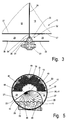
- FIG. 6 shows various representations a to c Positions of the drum 12 and thus the washing chamber 18 for one so-called pivoting washing movement. From all three representations 6 it can be seen that when washing the Laundry 11 the drum 12 compared to that in FIG. 5th loading and unloading position shown by half a circle (180 °) is rotated so that the inlet opening 40 and the outlet opening 41 in the upper region of the drum 12 in are located substantially above the longitudinal central axis 13. With the perforation 51 provided areas of the partition walls 28 are opposite the inlet opening 40 and the outlet opening 41, are then in the starting position (Fig. 6b) in Area of the lower half of the drum 12, that is, wherever also the laundry 11 and the wash water are located. The Wash water can flow through the perforation 51 in the partition walls 28 flow through the washing chamber 18 and also adjacent chambers, in particular in such a way that the washing water flows in counterflow, thus against the treatment direction 17, the drum 12 flows through.
- the swiveling washing movement starts from the middle position (Fig. 6b) of the washing chamber 18. From this middle position the drum 12 is alternated with the washing chamber 18 over a portion of the circumference in one direction and moves in the other direction, and always only so far that the Inlet opening 40 and the outlet opening 41 in an upper one Area of the drum 12 remain so that during the Washing movement neither through the inlet opening 40 nor through the outlet opening 41 wash water and especially laundry items 11 can get out of the washing chamber 18.
- the washing chamber 18 is turned in any direction rotated about 90 °. Starting from the starting position (Fig. 6b) for example, the drum 12 with the washing chamber 18 rotated clockwise about 90 ° (Fig. 6a) and then turned back 180 ° counterclockwise (Fig.
- the blades 39 in the compartments divide the compartments when it into the lower position shown in Figs. 4 and 5 have driven for loading and unloading.
- the division of the Chambers through the blades 39 is such that neither Laundry 11 still wash water from the entry opening 40 facing concave rear 42 of the blade 39 to that of Exit opening 41 facing convex front 43 of Can get shovel. Because of that on the entrance opening 41 facing concave back 42 of the blade 39 lying area of the cylinder jacket 27 of the chamber, in particular the washing chamber 18, liquid-tight , namely has no perforation 52, wash water can not within a chamber (the wash chamber 18 in FIG. 4) through the annular space 29 between the cylinder jacket 27 and the Flow the outer drum 23 under the blades 39.
- Another special feature of the method according to the invention refers to the fact that the respective relative position (rotary position) the drum 12 is determined. This investigation is preferably carried out without contact, namely continuously.
- a rotary angle encoder measures on the output shaft of the drive motor 26, the speed of the same, thereby drawing conclusions to the proportional rotation of the drum 12 can be derived.
- the measured values obtained in the above manner provide information about the angle of rotation by which the drum 12 has been rotated.
- the speed with which the drum 12 is rotated in particular the angular velocity or peripheral speed can be determined.
- the angular or circumferential speed can also be used Acceleration values of the drum 12 when starting and braking of the drive motor 26 determine.
- the measured values are used to around which the drum 12 when washing the laundry items 11 starting from the middle position (Fig. 6b) in one or other direction is twisted, monitor and to the each to be washed items of laundry 11 to adapt by a corresponding Increase or decrease the swivel angle when Washing the laundry 11.
- the measured values can also be used to: Transfer the drum 12 from the washing positions (Fig. 6a to 6c) in the loading and unloading position (FIG. 5) and to control. This ensures that in the case of Discharge of washing liquid from the washing chamber 18 (middle Chamber of Fig. 4) a drain on the drain box 53 only then is opened when the flow of washing liquid through the drum 12 from itself in the correct position located blades 39 is interrupted.
Landscapes
- Engineering & Computer Science (AREA)
- Textile Engineering (AREA)
- Accessory Of Washing/Drying Machine, Commercial Washing/Drying Machine, Other Washing/Drying Machine (AREA)
- Control Of Washing Machine And Dryer (AREA)
- Main Body Construction Of Washing Machines And Laundry Dryers (AREA)
- Treatment Of Fiber Materials (AREA)
- Detail Structures Of Washing Machines And Dryers (AREA)
Abstract
Description
- Fig. 1
- eine schematische Seitenansicht der Vorrichtung,
- Fig. 2
- eine detailliertere Seitenansicht der Vorrichtung,
- Fig. 3
- eine vergrößert dargestellte Einzelheit III aus der Fig. 2,
- Fig. 4
- einen vergrößerten Querschnitt durch drei Kammern der Vorrichtung in einer Stellung, bei der der Durchfluss der Behandlungsflüssigkeit durch die Vorrichtung im Bereich zweier Kammern unterbrochen ist,
- Fig. 5
- ein Querschnitt durch die Vorrichtung mit einer Ansicht auf eine Trennwand und eine Austrittsöffnung in einer Stellung analog zur Fig. 4, und
- Fig. 6a bis 6c
- eine Kammer der Vorrichtung in drei verschiedenen Waschstellungen.
- 10
- Durchlaufwaschmaschine
- 11
- Wäschestück
- 12
- Trommel
- 13
- Längsmittelachse
- 14
- Waschzone
- 15
- Spülzone
- 16
- Ausrüstzone
- 17
- Behandlungsrichtung
- 18
- Waschkammer
- 19
- Spülkammer
- 20
- Ausrüstkammer
- 21
- Eingabetrichter
- 22
- Ausgaberutsche
- 23
- Außentrommel
- 24
- Laufring
- 25
- Laufrad
- 26
- Antriebsmotor
- 27
- Zylindermantel
- 28
- Trennwand
- 29
- Ringraum
- 30
- Zylinderabschnitt
- 31
- Stirnseite
- 32
- Dichtung
- 33
- Stirnseite
- 34
- Quersteg
- 35
- Klaue
- 36
- Öffnung
- 37
- gerader Randbereich
- 38
- bogenförmiger Randbereich
- 39
- Schaufel
- 40
- Eintrittsöffnung
- 41
- Austrittsöffnung
- 42
- Rückseite
- 43
- Vorderseite
- 44
- Rand
- 45
- Rand
- 46
- Rand
- 47
- Querkante
- 48
- Spiralmittelpunkt
- 49
- Rippe
- 50
- Scheitelpunkt
- 51
- Perforation
- 52
- Perforation
- 53
- Ablaufkasten
Claims (16)
- Verfahren zum Nassbehandeln, insbesondere Waschen, von Wäschestücken, wobei in einer drehend antreibbaren Trommel die Wäschestücke in einer Behandlungsflüssigkeit behandelt und dabei längs durch die Trommel (in Behandlungsrichtung) hindurchgeleitet werden, und wobei vorzugsweise die Behandlungsflüssigkeit gegen die Behandlungsrichtung zurückgeleitet wird, dadurch gekennzeichnet, dass in der Trommel (12) Kammern gebildet sind und von mindestens einer der Kammern der Durchfluss der Behandlungsflüssigkeit unterbrochen wird bzw. unterbrochen werden kann.
- Verfahren nach Anspruch 1, dadurch gekennzeichnet, dass der Durchfluss der Behandlungsflüssigkeit durch die jeweilige Kammer nur in einer bestimmten (Winkel-)Stellung der Trommel (12) unterbrochen wird, vorzugsweise in einer solchen (Winkel-)Stellung der Trommel (12), in der ein Entladen und/ oder Beschicken der betreffenden Kammer erfolgt.
- Verfahren nach Anspruch 1 oder 2, dadurch gekennzeichnet, dass wenigstens einige Kammern während der Behandlung der darin sich befindenden Wäschestücke (11) von der Behandlungsflüssigkeit in Längsrichtung der Trommel (12) durchströmt werden, vorzugsweise gegen die Behandlungsrichtung (17).
- Verfahren nach einem der vorhergehenden Ansprüche, dadurch gekennzeichnet, dass in wenigstens einer Kammer die Behandlungsflüssigkeit bei Bedarf abgeführt wird, vorzugsweise die Behandlungsflüssigkeit (nur) abgeführt werden kann, wenn sich die Trommel (12) in einer solchen Position befindet, in der die betreffende Kammer mit Wäschestücken (11) beladen und/ oder entladen wird.
- Verfahren nach einem der vorhergehenden Ansprüche, dadurch gekennzeichnet, dass durch flüssigkeitsundurchlässige Schaufeln (39) in vorzugsweise mindestens zwei benachbarten Kammern ein Austausch der Behandlungsflüssigkeit zwischen von den Schaufeln (39) getrennten Teilen der Kammern verhindert wird, wobei vorzugsweise aus zueinanderweisenden, durch die flüssigkeitsdichten Schaufeln (39) getrennten Teilen benachbarter Kammern die Behandlungsflüssigkeit bei Bedarf abgeführt wird.
- Vorrichtung zur Nassbehandlung, insbesondere zum Waschen, von Wäschestücken, mit einer drehend antreibbaren Trommel, durch die die Wäschestücke in Längsrichtung (Behandlungsrichtung) hindurchtransportierbar sind und dabei die Nassbehandlung (Wäsche) der Wäschestücke erfolgt, dadurch gekennzeichnet, dass die Trommel (12) durch quer zu ihrer Längsmittelmittelachse (13) verlaufende Trennwände (28) in einzelne Kammern unterteilt ist.
- Vorrichtung nach Anspruch 6, dadurch gekennzeichnet, dass in den Kammern flüssigkeitsundurchlässige Schaufeln (39) angeordnet sind, wobei die Schaufeln (39) spiralförmig, insbesondere nach einer achimedischen Spirale, ausgebildet sind.
- Vorrichtung nach einem der vorhergehenden Ansprüche, dadurch gekennzeichnet, dass jede Kammer von einem einen Teil der Trommel (12) bildenden (kürzeren) Zylindermantel (27) umgeben ist.
- Vorrichtung nach einem der vorhergehenden Ansprüche, dadurch gekennzeichnet, dass jede Schaufel auf einer Seite neben der Längsmittelachse (13) der Trommel (12) bzw. der betreffenden Kammer sich erstreckt, vorzugsweise über einen Bereich eines Kreisabschnitts der zylindrischen Kammer, wobei sich der Kreisabschnitt insbesondere über einen Umfangsbereich des Zylindermantels (27) von etwa 80° bis 150° erstreckt.
- Vorrichtung nach einem der vorhergehenden Ansprüche, dadurch gekennzeichnet, dass ein äußerer Rand (44) der spiralförmigen Schaufel (39) mit dem Zylindermantel (27) verbunden ist und sich vorzugsweise schräg durch die Kammer zwischen gegenüberliegenden Trennwänden (28) zur Begrenzung gegenüberliegender Stirnseiten der Kammer erstreckt.
- Vorrichtung nach einem der vorhergehenden Ansprüche, dadurch gekennzeichnet, dass in einem auf die Trennwände (28) projizierten Bereich der jeweiligen Schaufel (39) jede Trennwand (28) eine Öffnung (36) aufweist, wobei die Öffnungen (36) an gegenüberliegenden Trennwänden (28) der jeweiligen Kammer, vorzugsweise aller Kammern, sich gegenüberliegen, und vorzugsweise die Öffnung (36) in der jeweiligen Trennwand (28) sich im wesentlichen nur über einen Halbkreisbereich der Trennwand (28) erstreckt.
- Vorrichtung nach einem der vorhergehenden Ansprüche, dadurch gekennzeichnet, dass mindestens ein Teilbereich der oder jeder Trennwand (28) flüssigkeitsdurchlässig ausgebildet ist, vorzugsweise eine Perforation (51) aufweist, wobei vorzugsweise im wesentlichen nur ein der jeweiligen Öffnung (36) in der Trennwand (28) gegenüberliegender oder maximal ein Halbkreisbereich füssigkeitsdurchlässig ausgebildet ist.
- Vorrichtung nach einem der vorhergehenden Ansprüche, dadurch gekennzeichnet, dass der Zylindermantel (27) teilweise, insbesondere größtenteils, flüssigkeitsdurchlässig ausgebildet ist, insbesondere eine Perforation (52) aufweist, wobei vorzugsweise ein sich mindestens über den mit dem Zylindermantel (27) verbundenen äußeren Rand (44) der Schaufel (39) erstreckender Teilbereich des Zylindermantels (27) auf einer Seite der mit dem Rand (44) schräg durch die Kammer verlaufenden Schaufel (39) flüssigkeitsundurchlässig ist.
- Vorrichtung nach einem der vorhergehenden Ansprüche, dadurch gekennzeichnet, dass der keine Perforation (52) aufweisende Bereich des Zylindermantels (27) sich nur auf einer Seite der Schaufel (39) befindet, vorzugsweise einer zur Eintrittsöffnung (40) der Wäschestücke (11) und gegebenenfalls Behandlungsflüssigkeit gerichteten, konkaven Seite (Rückseite 42) der Schaufel (39).
- Verfahren zur Nassbehandlung, insbesondere Waschen, von Wäschestücken, wobei in einer drehend antreibbaren Trommel die Wäschestücke behandelt (gewaschen) werden, insbesondere nach einem der vorhergehenden Ansprüche, dadurch gekennzeichnet, dass während der Behandlung der Drehwinkel bzw. drehwinkelproportionale Werte der Trommel (12) und/oder die Winkelgeschwindigkeit oder winkelgeschwindigkeitsproportionale Werte der Trommel (12)vorzugsweise berührungslos und/oder kontinuierlich gemessen werden.
- Verfahren nach einem der vorhergehenden Ansprüche, dadurch gekennzeichnet, dass mindestens einer der vorzugsweise kontinuierlich und/oder berührungslos gemessenen Werte zur insbesondere von der Art der Wäschestücke (11) abhängigen programmgesteuerten Behandlung der Wäschestücke verwendet wird, vorzugsweise hinsichtlich der Schwenkbewegung (Schwenkwinkel) der Trommel (12) und/oder der Beschleunigung beim Anfahren und Abbremsen des drehenden Antriebs der Trommel (12).
Priority Applications (1)
| Application Number | Priority Date | Filing Date | Title |
|---|---|---|---|
| EP06001589A EP1655402A3 (de) | 1999-08-30 | 2000-08-14 | Verfahren zum Nassbehandeln, insbesondere Waschen, von Wäschestücken |
Applications Claiming Priority (3)
| Application Number | Priority Date | Filing Date | Title |
|---|---|---|---|
| DE19941088 | 1999-08-30 | ||
| DE19964359 | 1999-08-30 | ||
| DE1999141088 DE19941088B4 (de) | 1999-08-30 | 1999-08-30 | Verfahren zum Naßbehandeln, insbesondere Waschen, von Wäschestücken |
Related Child Applications (1)
| Application Number | Title | Priority Date | Filing Date |
|---|---|---|---|
| EP06001589A Division EP1655402A3 (de) | 1999-08-30 | 2000-08-14 | Verfahren zum Nassbehandeln, insbesondere Waschen, von Wäschestücken |
Publications (3)
| Publication Number | Publication Date |
|---|---|
| EP1081266A2 true EP1081266A2 (de) | 2001-03-07 |
| EP1081266A3 EP1081266A3 (de) | 2003-02-12 |
| EP1081266B1 EP1081266B1 (de) | 2006-06-07 |
Family
ID=36440980
Family Applications (1)
| Application Number | Title | Priority Date | Filing Date |
|---|---|---|---|
| EP20000117242 Expired - Lifetime EP1081266B1 (de) | 1999-08-30 | 2000-08-14 | Verfahren und Vorrichtung zum Nassbehandeln, insbesondere Waschen, von Wäschestücken |
Country Status (3)
| Country | Link |
|---|---|
| EP (1) | EP1081266B1 (de) |
| DE (2) | DE19941088B4 (de) |
| ES (1) | ES2265843T3 (de) |
Families Citing this family (2)
| Publication number | Priority date | Publication date | Assignee | Title |
|---|---|---|---|---|
| DE102010050489A1 (de) * | 2010-11-08 | 2012-05-10 | Herbert Kannegiesser Gmbh | Verfahren und Vorrichtung zur Nassbehandlung, insbesondere zum Waschen, von Wäschestücken |
| WO2023003946A1 (en) * | 2021-07-20 | 2023-01-26 | Pellerin Milnor Corporation | Tunnel washing machine |
Family Cites Families (15)
| Publication number | Priority date | Publication date | Assignee | Title |
|---|---|---|---|---|
| DE7421543U (de) * | 1976-01-02 | Schaper, Karl, 3203 Sarstedt | Durchlaufwaschmaschine | |
| US3330139A (en) * | 1965-03-08 | 1967-07-11 | Schafer Konrad | Apparatus for the treatment of textiles or fabrics or the washing of laundry |
| DE7226900U (de) * | 1972-07-20 | 1972-10-05 | Vosswerke Gmbh | Durchlaufwaschmaschine |
| DE2312003A1 (de) * | 1973-03-10 | 1974-09-26 | Poensgen Gmbh Geb | Durchlaufwaschmaschine |
| DE2345943C3 (de) * | 1973-09-12 | 1979-10-31 | Engelhardt & Foerster, 2800 Bremen | Doppeltrommel-Gegenstrom-Durchlaufwaschmaschine |
| AT344118B (de) * | 1976-09-06 | 1978-07-10 | Poensgen & Sulzmann Gmbh Geb | Trommelmaschine zum postenweisen nassbehandeln von textilien |
| US4236393A (en) * | 1979-07-19 | 1980-12-02 | Pellerin Milnor Corporation | Continuous tunnel batch washer |
| DE2949228C2 (de) * | 1979-12-07 | 1986-04-17 | Engelhardt & Förster, 2800 Bremen | Durchlaufwaschmaschine |
| US4485509A (en) * | 1981-04-17 | 1984-12-04 | Pellerin Milnor Corporation | Continuous batch type washing machine and method for operating same |
| DE3239080A1 (de) * | 1981-12-17 | 1983-08-25 | Veb Kombinat Textima, Ddr 9010 Karl-Marx-Stadt | Durchlaufmaschine zur behandlung tierischer haeute und felle |
| US5211039A (en) * | 1991-03-12 | 1993-05-18 | Pellerin Milnor Corporation | Continuous batch type washing machine |
| DE4108643C2 (de) * | 1991-03-16 | 1996-05-02 | Rolf Herkenrath | Verfahren zur Verminderung des Wasser- und Energieverbrauchs beim Betreiben einer Waschmaschinenstraße |
| US5307652A (en) * | 1991-11-28 | 1994-05-03 | Mitsubishi Jukogyo Kabushiki Kaisha | Continuous washing machine |
| EP0636731A1 (de) * | 1993-07-28 | 1995-02-01 | Senkingwerk GmbH | Verfahren zum Waschen von Wäsche in einer Gegenstrom-Durchlaufwaschmaschine |
| US5454237A (en) * | 1994-04-13 | 1995-10-03 | Pellerin Milnor Corporation | Continuous batch type washing machine |
-
1999
- 1999-08-30 DE DE1999141088 patent/DE19941088B4/de not_active Expired - Fee Related
-
2000
- 2000-08-14 DE DE50012896T patent/DE50012896D1/de not_active Expired - Lifetime
- 2000-08-14 EP EP20000117242 patent/EP1081266B1/de not_active Expired - Lifetime
- 2000-08-14 ES ES00117242T patent/ES2265843T3/es not_active Expired - Lifetime
Also Published As
| Publication number | Publication date |
|---|---|
| ES2265843T3 (es) | 2007-03-01 |
| DE50012896D1 (de) | 2006-07-20 |
| DE19941088B4 (de) | 2006-06-01 |
| EP1081266A3 (de) | 2003-02-12 |
| DE19941088A1 (de) | 2001-03-01 |
| EP1081266B1 (de) | 2006-06-07 |
Similar Documents
| Publication | Publication Date | Title |
|---|---|---|
| DE2330915A1 (de) | Verfahren und vorrichtung zum ausscheiden von feststoffen aus fluessigkeiten | |
| DE8019405U1 (de) | Wascheinrichtung | |
| DE4204851A1 (de) | Kontinuierlich arbeitende chargenwaschmaschine | |
| DE19513780A1 (de) | Chargen-Waschmaschine mit kontinuierlicher Arbeitsweise | |
| EP1028189A2 (de) | Trommelwaschmaschine mit einer Wäschetrommel, deren Trommelmantel eine strukturierte Oberfläche aufweist | |
| DE2648057B2 (de) | Vorrichtung zum Gerben, Färben o.dgl | |
| DE9309162U1 (de) | Waschmaschine zum Reinigen langgestreckter Werkstücke | |
| DE3881020T2 (de) | Trommel waschmaschine. | |
| DE1303233B (de) | ||
| DE2745787C3 (de) | Programmgesteuerte Postenwaschmaschine | |
| EP1081266B1 (de) | Verfahren und Vorrichtung zum Nassbehandeln, insbesondere Waschen, von Wäschestücken | |
| EP1081267A2 (de) | Verfahren und Vorrichtung zum Nassbehandeln, insbesondere Waschen, von Wäschestücken | |
| DE3043657C2 (de) | ||
| DE2041207A1 (de) | Waschmaschine | |
| CH492816A (de) | Nach dem Gegenstromprinzip arbeitende, rohrförmige Doppeltrommelwaschmaschine | |
| WO2000037729A1 (de) | Wäschetrommel | |
| DE10105820B4 (de) | Verfahren zum Waschen von insbesondere Wäschestücken | |
| DE69208323T2 (de) | Durchlaufwaschmaschine für Textilien oder dergleichen | |
| EP1655402A2 (de) | Verfahren zum Nassbehandeln, insbesondere Waschen, von Wäschestücken | |
| DE2739876B2 (de) | Trommelwaschmaschine o.dgl | |
| DE2235599A1 (de) | Durchlaufwaschmaschine | |
| DE806849C (de) | Wasch-, Trockenreinigungs- oder Faerbemaschine | |
| EP1989349B1 (de) | Verfahren und vorrichtung zum nassbehandeln von wäsche | |
| EP0636731A1 (de) | Verfahren zum Waschen von Wäsche in einer Gegenstrom-Durchlaufwaschmaschine | |
| DE2241099A1 (de) | Rohrfoermige waschmaschine |
Legal Events
| Date | Code | Title | Description |
|---|---|---|---|
| PUAI | Public reference made under article 153(3) epc to a published international application that has entered the european phase |
Free format text: ORIGINAL CODE: 0009012 |
|
| AK | Designated contracting states |
Kind code of ref document: A2 Designated state(s): AT BE CH CY DE DK ES FI FR GB GR IE IT LI LU MC NL PT SE |
|
| AX | Request for extension of the european patent |
Free format text: AL;LT;LV;MK;RO;SI |
|
| PUAL | Search report despatched |
Free format text: ORIGINAL CODE: 0009013 |
|
| AK | Designated contracting states |
Designated state(s): AT BE CH CY DE DK ES FI FR GB GR IE IT LI LU MC NL PT SE |
|
| AX | Request for extension of the european patent |
Extension state: AL LT LV MK RO SI |
|
| 17P | Request for examination filed |
Effective date: 20030708 |
|
| AKX | Designation fees paid |
Designated state(s): DE ES FR GB IT |
|
| 17Q | First examination report despatched |
Effective date: 20031024 |
|
| GRAP | Despatch of communication of intention to grant a patent |
Free format text: ORIGINAL CODE: EPIDOSNIGR1 |
|
| RTI1 | Title (correction) |
Free format text: METHOD AND DEVICE FOR WET TREATMENT, PARTICULARLY WASHING OF LAUNDRY |
|
| GRAS | Grant fee paid |
Free format text: ORIGINAL CODE: EPIDOSNIGR3 |
|
| GRAA | (expected) grant |
Free format text: ORIGINAL CODE: 0009210 |
|
| AK | Designated contracting states |
Kind code of ref document: B1 Designated state(s): DE ES FR GB IT |
|
| REG | Reference to a national code |
Ref country code: GB Ref legal event code: FG4D Free format text: NOT ENGLISH |
|
| REF | Corresponds to: |
Ref document number: 50012896 Country of ref document: DE Date of ref document: 20060720 Kind code of ref document: P |
|
| GBT | Gb: translation of ep patent filed (gb section 77(6)(a)/1977) |
Effective date: 20061107 |
|
| ET | Fr: translation filed | ||
| REG | Reference to a national code |
Ref country code: ES Ref legal event code: FG2A Ref document number: 2265843 Country of ref document: ES Kind code of ref document: T3 |
|
| PLBE | No opposition filed within time limit |
Free format text: ORIGINAL CODE: 0009261 |
|
| STAA | Information on the status of an ep patent application or granted ep patent |
Free format text: STATUS: NO OPPOSITION FILED WITHIN TIME LIMIT |
|
| 26N | No opposition filed |
Effective date: 20070308 |
|
| PGFP | Annual fee paid to national office [announced via postgrant information from national office to epo] |
Ref country code: FR Payment date: 20100824 Year of fee payment: 11 |
|
| PGFP | Annual fee paid to national office [announced via postgrant information from national office to epo] |
Ref country code: GB Payment date: 20100811 Year of fee payment: 11 |
|
| PGFP | Annual fee paid to national office [announced via postgrant information from national office to epo] |
Ref country code: IT Payment date: 20110812 Year of fee payment: 12 |
|
| GBPC | Gb: european patent ceased through non-payment of renewal fee |
Effective date: 20110814 |
|
| REG | Reference to a national code |
Ref country code: FR Ref legal event code: ST Effective date: 20120430 |
|
| PG25 | Lapsed in a contracting state [announced via postgrant information from national office to epo] |
Ref country code: FR Free format text: LAPSE BECAUSE OF NON-PAYMENT OF DUE FEES Effective date: 20110831 Ref country code: GB Free format text: LAPSE BECAUSE OF NON-PAYMENT OF DUE FEES Effective date: 20110814 |
|
| REG | Reference to a national code |
Ref country code: DE Ref legal event code: R082 Ref document number: 50012896 Country of ref document: DE Representative=s name: MEISSNER, BOLTE & PARTNER GBR, DE |
|
| REG | Reference to a national code |
Ref country code: DE Ref legal event code: R082 Ref document number: 50012896 Country of ref document: DE Representative=s name: MEISSNER BOLTE PATENTANWAELTE RECHTSANWAELTE P, DE Effective date: 20130405 Ref country code: DE Ref legal event code: R082 Ref document number: 50012896 Country of ref document: DE Representative=s name: MEISSNER, BOLTE & PARTNER GBR, DE Effective date: 20130405 Ref country code: DE Ref legal event code: R081 Ref document number: 50012896 Country of ref document: DE Owner name: HERBERT KANNEGIESSER GMBH, DE Free format text: FORMER OWNER: PHARMAGG SYSTEMTECHNIK GMBH, 27318 HOYA, DE Effective date: 20130405 |
|
| PG25 | Lapsed in a contracting state [announced via postgrant information from national office to epo] |
Ref country code: IT Free format text: LAPSE BECAUSE OF NON-PAYMENT OF DUE FEES Effective date: 20120814 |
|
| PGFP | Annual fee paid to national office [announced via postgrant information from national office to epo] |
Ref country code: ES Payment date: 20140812 Year of fee payment: 15 |
|
| REG | Reference to a national code |
Ref country code: ES Ref legal event code: FD2A Effective date: 20160926 |
|
| PG25 | Lapsed in a contracting state [announced via postgrant information from national office to epo] |
Ref country code: ES Free format text: LAPSE BECAUSE OF NON-PAYMENT OF DUE FEES Effective date: 20150815 |
|
| PGFP | Annual fee paid to national office [announced via postgrant information from national office to epo] |
Ref country code: DE Payment date: 20180629 Year of fee payment: 19 |
|
| REG | Reference to a national code |
Ref country code: DE Ref legal event code: R119 Ref document number: 50012896 Country of ref document: DE |
|
| PG25 | Lapsed in a contracting state [announced via postgrant information from national office to epo] |
Ref country code: DE Free format text: LAPSE BECAUSE OF NON-PAYMENT OF DUE FEES Effective date: 20200303 |