EP1081275A2 - Procédé de fabrication d'une bande sans fin pour machines à papier - Google Patents
Procédé de fabrication d'une bande sans fin pour machines à papier Download PDFInfo
- Publication number
- EP1081275A2 EP1081275A2 EP00102182A EP00102182A EP1081275A2 EP 1081275 A2 EP1081275 A2 EP 1081275A2 EP 00102182 A EP00102182 A EP 00102182A EP 00102182 A EP00102182 A EP 00102182A EP 1081275 A2 EP1081275 A2 EP 1081275A2
- Authority
- EP
- European Patent Office
- Prior art keywords
- base fabric
- polymeric resin
- belt
- conveyor belt
- yarns
- Prior art date
- Legal status (The legal status is an assumption and is not a legal conclusion. Google has not performed a legal analysis and makes no representation as to the accuracy of the status listed.)
- Withdrawn
Links
Images






Classifications
-
- D—TEXTILES; PAPER
- D21—PAPER-MAKING; PRODUCTION OF CELLULOSE
- D21G—CALENDERS; ACCESSORIES FOR PAPER-MAKING MACHINES
- D21G1/00—Calenders; Smoothing apparatus
- D21G1/006—Calenders; Smoothing apparatus with extended nips
-
- D—TEXTILES; PAPER
- D21—PAPER-MAKING; PRODUCTION OF CELLULOSE
- D21G—CALENDERS; ACCESSORIES FOR PAPER-MAKING MACHINES
- D21G9/00—Other accessories for paper-making machines
-
- B—PERFORMING OPERATIONS; TRANSPORTING
- B29—WORKING OF PLASTICS; WORKING OF SUBSTANCES IN A PLASTIC STATE IN GENERAL
- B29C—SHAPING OR JOINING OF PLASTICS; SHAPING OF MATERIAL IN A PLASTIC STATE, NOT OTHERWISE PROVIDED FOR; AFTER-TREATMENT OF THE SHAPED PRODUCTS, e.g. REPAIRING
- B29C39/00—Shaping by casting, i.e. introducing the moulding material into a mould or between confining surfaces without significant moulding pressure; Apparatus therefor
- B29C39/14—Shaping by casting, i.e. introducing the moulding material into a mould or between confining surfaces without significant moulding pressure; Apparatus therefor for making articles of indefinite length
- B29C39/18—Shaping by casting, i.e. introducing the moulding material into a mould or between confining surfaces without significant moulding pressure; Apparatus therefor for making articles of indefinite length incorporating preformed parts or layers, e.g. casting around inserts or for coating articles
-
- B—PERFORMING OPERATIONS; TRANSPORTING
- B29—WORKING OF PLASTICS; WORKING OF SUBSTANCES IN A PLASTIC STATE IN GENERAL
- B29C—SHAPING OR JOINING OF PLASTICS; SHAPING OF MATERIAL IN A PLASTIC STATE, NOT OTHERWISE PROVIDED FOR; AFTER-TREATMENT OF THE SHAPED PRODUCTS, e.g. REPAIRING
- B29C70/00—Shaping composites, i.e. plastics material comprising reinforcements, fillers or preformed parts, e.g. inserts
- B29C70/04—Shaping composites, i.e. plastics material comprising reinforcements, fillers or preformed parts, e.g. inserts comprising reinforcements only, e.g. self-reinforcing plastics
- B29C70/06—Fibrous reinforcements only
- B29C70/10—Fibrous reinforcements only characterised by the structure of fibrous reinforcements, e.g. hollow fibres
- B29C70/16—Fibrous reinforcements only characterised by the structure of fibrous reinforcements, e.g. hollow fibres using fibres of substantial or continuous length
- B29C70/22—Fibrous reinforcements only characterised by the structure of fibrous reinforcements, e.g. hollow fibres using fibres of substantial or continuous length oriented in at least two directions forming a two-dimensional [2D] structure
-
- B—PERFORMING OPERATIONS; TRANSPORTING
- B29—WORKING OF PLASTICS; WORKING OF SUBSTANCES IN A PLASTIC STATE IN GENERAL
- B29D—PRODUCING PARTICULAR ARTICLES FROM PLASTICS OR FROM SUBSTANCES IN A PLASTIC STATE
- B29D29/00—Producing belts or bands
-
- D—TEXTILES; PAPER
- D21—PAPER-MAKING; PRODUCTION OF CELLULOSE
- D21F—PAPER-MAKING MACHINES; METHODS OF PRODUCING PAPER THEREON
- D21F3/00—Press section of machines for making continuous webs of paper
-
- D—TEXTILES; PAPER
- D21—PAPER-MAKING; PRODUCTION OF CELLULOSE
- D21F—PAPER-MAKING MACHINES; METHODS OF PRODUCING PAPER THEREON
- D21F3/00—Press section of machines for making continuous webs of paper
- D21F3/02—Wet presses
- D21F3/0209—Wet presses with extended press nip
- D21F3/0218—Shoe presses
- D21F3/0227—Belts or sleeves therefor
-
- D—TEXTILES; PAPER
- D21—PAPER-MAKING; PRODUCTION OF CELLULOSE
- D21F—PAPER-MAKING MACHINES; METHODS OF PRODUCING PAPER THEREON
- D21F3/00—Press section of machines for making continuous webs of paper
- D21F3/02—Wet presses
- D21F3/0209—Wet presses with extended press nip
- D21F3/0218—Shoe presses
- D21F3/0227—Belts or sleeves therefor
- D21F3/0236—Belts or sleeves therefor manufacturing methods
-
- D—TEXTILES; PAPER
- D21—PAPER-MAKING; PRODUCTION OF CELLULOSE
- D21G—CALENDERS; ACCESSORIES FOR PAPER-MAKING MACHINES
- D21G1/00—Calenders; Smoothing apparatus
- D21G1/0066—Calenders; Smoothing apparatus using a special calendering belt
-
- B—PERFORMING OPERATIONS; TRANSPORTING
- B29—WORKING OF PLASTICS; WORKING OF SUBSTANCES IN A PLASTIC STATE IN GENERAL
- B29L—INDEXING SCHEME ASSOCIATED WITH SUBCLASS B29C, RELATING TO PARTICULAR ARTICLES
- B29L2031/00—Other particular articles
- B29L2031/733—Fourdrinier belts
-
- Y—GENERAL TAGGING OF NEW TECHNOLOGICAL DEVELOPMENTS; GENERAL TAGGING OF CROSS-SECTIONAL TECHNOLOGIES SPANNING OVER SEVERAL SECTIONS OF THE IPC; TECHNICAL SUBJECTS COVERED BY FORMER USPC CROSS-REFERENCE ART COLLECTIONS [XRACs] AND DIGESTS
- Y10—TECHNICAL SUBJECTS COVERED BY FORMER USPC
- Y10S—TECHNICAL SUBJECTS COVERED BY FORMER USPC CROSS-REFERENCE ART COLLECTIONS [XRACs] AND DIGESTS
- Y10S162/00—Paper making and fiber liberation
- Y10S162/901—Impermeable belts for extended nip press
Definitions
- the present invention relates to mechanisms for extracting water from a web of material, and, more particularly, from a fibrous web being processed into a paper product on a papermaking machine.
- the present invention is a method for manufacturing resin-impregnated endless belt structures designed for use on a long nip press of the shoe type on a papermaking machine, and for other papermaking and paper-processing applications.
- a fibrous web of cellulosic fibers is formed on a forming wire by depositing a fibrous slurry thereon in the forming section of a papermachine.
- a large amount of water is drained from the slurry in the forming section, after which the newly formed web is conducted to a press section.
- the press section includes a series of press nips, in which the fibrous web is subjected to compressive forces applied to remove water therefrom.
- the web finally is conducted to a drying section which includes heated dryer drums around which the web is directed. The heated dryer drums reduce the water content of the web to a desirable level through evaporation to yield a paper product.
- press sections have included a series of nips formed by pairs of adjacent cylindrical press rolls.
- the use of long press nips of the shoe type has been found to be more advantageous than the use of nips formed by pairs of adjacent press rolls. This is because the longer the time a web can be subjected to pressure in the nip, the more water can be removed there, and, consequently, the less water will remain behind in the web for removal through evaporation in the dryer section.
- the present invention relates to long nip presses of the shoe type.
- the nip is formed between a cylindrical press roll and an arcuate pressure shoe.
- the latter has a cylindrically concave surface having a radius of curvature close to that of the cylindrical press roll.
- a nip which can be five to ten times longer in the machine direction than one formed between two press rolls is formed. Since the long nip may be five to ten times longer than that in a conventional two-roll press, the so-called dwell time, during which the fibrous web is under pressure in the long nip, may be correspondingly longer than it would be in a two-roll press.
- the result of this new long nip technology has been a dramatic increase in the dewatering of the fibrous web in the long nip when compared to that in conventional nips on paper machines.
- a long nip press of the shoe type requires a special belt, such as that shown in U.S. Patent No. 5,238,537.
- This belt is designed to protect the press fabric supporting, carrying and dewatering the fibrous web from the accelerated wear that would result from direct, sliding contact over the stationary pressure shoe.
- Such a belt must be provided with a smooth, impervious surface that rides, or slides, over the stationary shoe on a lubricating film of oil. The belt moves through the nip at roughly the same speed as the press fabric, thereby subjecting the press fabric to minimal amounts of rubbing against the surface of the belt.
- Belts of the variety shown in U.S. Patent No. 5,238,537 are made by impregnating a woven base fabric, which takes the form of an endless loop, with a synthetic polymeric resin.
- the resin forms a coating of some predetermined thickness on at least the inner surface of the belt, so that the yarns from which the base fabric is woven may be protected from direct contact with the arcuate pressure shoe component of the long nip press. It is specifically this coating which must have a smooth, impervious surface to slide readily over the lubricated shoe and to prevent any of the lubricating oil from penetrating the structure of the belt to contaminate the press fabric, or fabrics, and fibrous web.
- the base fabric of the belt shown in U.S. Patent No. 5,238,537 may be woven from monofilament yarns in a single- or multi-layer weave, and is woven so as to be sufficiently open to allow the impregnating material to totally impregnate the weave. This eliminates the possibility of any voids forming in the final belt. Such voids may allow the lubrication used between the belt and shoe to pass through the belt and contaminate the press fabric or fabrics and fibrous web.
- the base fabric may be flat-woven, and subsequently seamed into endless form, or woven endless in tubular form.
- the impregnating material When the impregnating material is cured to a solid condition, it is primarily bound to the base fabric by a mechanical interlock, wherein the cured impregnating material surrounds the yarns of the base fabric. In addition, there may be some chemical bonding or adhesion between the cured impregnating material and the material of the yarns of the base fabric.
- Long nip press belts such as that shown in U.S. Patent No. 5,238,537, depending on the size requirements of the long nip presses on which they are installed, have lengths from roughly 13 to 35 feet (approximately 4 to 11 meters), measured longitudinally around their endless-loop forms, and widths from roughly 100 to 450 inches (approximately 250 to 1125 centimeters), measured transversely across those forms.
- the present invention provides a solution to these problems, which characterize prior-art methods for manufacturing resin-impregnated endless belt structures, by including the use of an endless base fabric having a more open structure than those of the prior art to decrease the likelihood that air will be trapped therewithin, and by providing a layer of the polymeric resin material on the inner surface of the belt without having to turn the belt inside out at any time during the manufacturing process.
- the object of the present invention is to provide a method for manufacturing a resin-impregnated endless belt for use in the papermaking process or in other industrial applications where an endless belt, impermeable to water, oil and other fluids, and having at least one smooth uniform side, a uniform thickness, abrasion resistance and required hardness characteristics, is desirable.
- One such application is as a belt used on long nip presses of the shoe type on paper machines.
- the belt needs to be smooth and impervious to oil on the side that rides on the lubricating oil film on the shoe, which forms one side of the nip.
- the side away from the shoe can be smooth or can be provided with void volume, in the form of grooves or blind-drilled holes, into which water expressed from a paper web in the nip can pass.
- a second such application is as a belt used for the calendering of paper either in a roll nip or in a long shoe-type nip.
- Such a belt is required to be smooth on both sides, impermeable to oil (when used in a calender having a long shoe-type nip), of uniform thickness, and having the hardnesses required for each side.
- the resin-impregnated endless belt comprises a base fabric in the form of an endless loop with an inner surface, an outer surface, a machine direction and a cross-machine direction.
- the base fabric has machine-direction (MD) structural elements and cross-machine-direction (CD) structural elements, wherein at least some of the MD structural elements are spaced apart from one another by a distance in the range from 0.0625 inch to 0.5 inch (0.16 cm to 1.27 cm), and wherein at least some of the CD structural elements are spaced apart from one another by a distance in the range from 0.0625 inch to 0.5 inch (0.16 cm to 1.27 cm).
- the MD structural elements cross or are interwoven with the CD structural elements at a plurality of crossing points, where the MD structural elements and the CD structural elements are joined to one another. The joining may be by mechanical, chemical or thermobonding means.
- the base fabric may be a spiral-link fabric of the variety shown in many U.S. patents, such as Patent No. 4,567,077 to Gauthier, the teachings of which are incorporated herein by reference, so long as the individual turns of the spirals making up the spiral-link fabric are spaced from one another by amounts in the range set forth above.
- the belt further comprises a coating of a polymeric resin on the inner surface of the base fabric.
- the coating impregnates and renders the base fabric impermeable to liquids, and forms a layer on the inner surface thereof.
- the coating is smooth and provides the belt with a uniform thickness.
- the resin impregnate fills the space on the inside of the fabric, the voids in the fabric structure, and also provides a layer of resin on the outside of the fabric structure.
- the present method for manufacturing the resin-impregnated endless belt requires the use of a first roll and a second roll.
- the base fabric is disposed about the first and second rolls, which are then moved apart from one another to place the base fabric under tension in the machine direction.
- a conveyor belt entrained about a third and fourth roll, is placed within the endless loop formed by the base fabric.
- a sidewall is provided against one side of the conveyor belt.
- the conveyor belt is disposed adjacent to a lateral edge of the base fabric, with the sidewall inward of the conveyor belt relative to the lateral edge, and is separated from the inner surface of the base fabric by a preselected distance.
- the base fabric and conveyor belt are then set into motion by rotating the first and second rolls and the third and fourth rolls, respectively, at a common speed, and, starting adjacent to the lateral edge, the polymeric resin is dispensed onto the base fabric at a point over the conveyor belt from a dispenser in the form of a stream.
- the dispenser, conveyor belt and sidewall are moved transversely relative to the base fabric, the sidewall preventing the polymeric resin from flowing laterally relative to the base fabric, to apply the polymeric resin onto the base fabric in the form of a spiral of a preselected thickness to impregnate the base fabric therewith and to form a layer of the polymeric resin of a thickness equal to the preselected distance separating the conveyor belt from the inner surface of the base fabric on the inner surface.
- the polymeric resin cures by crosslinking as the coating process proceeds across the base fabric.
- the outer surface of the belt may be finished to a smooth surface or to a surface containing void volume.
- the present method may be used to manufacture resin-impregnated belt structures for use in all phases of the papermaking industry. That is to say, the endless belt structures may be used as roll covers, as belts for calenders of the roll and shoe types, as well as on long nip presses (LNP) of the shoe type, and as coater, pre-press and transfer belts.
- LNP long nip presses
- a long nip press (LNP) for dewatering a fibrous web being processed into a paper product on a paper machine is shown in a side cross-sectional view in Figure 1.
- the press nip 10 is defined by a smooth cylindrical press roll 12 and an arcuate pressure shoe 14.
- the arcuate pressure shoe 14 has about the same radius of curvature as the cylindrical press roll 12.
- the distance between the cylindrical press roll 12 and the arcuate pressure shoe 14 may be adjusted by hydraulic means operatively attached to arcuate pressure shoe 14 to control the loading of the nip 10.
- Smooth cylindrical press roll 12 may be a controlled crown roll matched to the arcuate pressure shoe 14 to obtain a level cross-machine nip profile.
- Endless belt structure 16 extends in a closed loop through nip 10, separating press roll 12 from arcuate pressure shoe 14.
- a press fabric 18 and a fibrous web 20 being processed into a paper sheet pass together through nip 10 as indicated by the arrows in Figure 1.
- Fibrous web 20 is supported by press fabric 18 and comes into direct contact with smooth cylindrical press roll 12 in nip 10. Fibrous web 20 and press fabric 18 proceed through the nip 10 as indicated by the arrows.
- fibrous web 20 may proceed through the nip 10 between two press fabrics 18.
- the press roll 12 may be either smooth or provided with void-volume means, such as grooves or blind-drilled holes.
- the side of endless belt structure 16 facing the press fabrics 18 may also be smooth or provided with void-volume means.
- endless belt structure 16 also moving through press nip 10 as indicated by the arrows, that is, counter-clockwise as depicted in Figure 1, protects press fabric 18 from direct sliding contact against arcuate pressure shoe 14, and slides thereover on a lubricating film of oil.
- a perspective view of belt 16 is provided in Figure 2.
- the belt 16 has an inner surface 28 and an outer surface 30.
- the outer surface 30 is finished to a smooth surface.
- FIG 3 is a perspective view of an alternate embodiment of the belt 32.
- the belt 32 has an inner surface 34 and an outer surface 36.
- the outer surface 36 is provided with a plurality of grooves 38, for example, in the longitudinal direction around the belt 32 for the temporary storage of water pressed from fibrous web 20 in press nip 10.
- the outer surface of the belt may be provided with a plurality of blind-drilled holes arranged in some desired geometric pattern for the temporary storage of water.
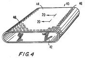
- Figure 4 is a perspective view of such an alternate embodiment of the belt 40.
- the belt 40 has an inner surface 42 and an outer surface 44.
- the outer surface 44 is provided with a plurality of blind-drilled holes 46, so called because they do not extend completely through the belt 40.
- the blind-drilled holes 46 could also be connected to one another by grooves.
- the belt includes a base fabric having machine-direction (MD) and cross-machine-direction (CD) structural elements and having a much higher open area than that characterizing the base fabrics of the prior art. Because the base fabric has such a high open area, it cannot be produced using conventional techniques alone, which tend to leave a high-open-area fabric sleazy, dimensionally unstable, and readily distorted. To avoid these potential shortcomings, the base fabric has an open structure in which the MD and CD structural elements are joined to one another at their crossing points by mechanical, chemical or thermal means.
- MD machine-direction
- CD cross-machine-direction
- the base fabric may be woven in an endless leno weave.
- a plan view of such a base fabric 50 is shown in Figure 5.
- Base fabric 50 is woven from warp yarns 52,54 and weft yarns 56.
- Warp yarns 52,54 twist one around the other between picks of weft yarn 56.
- Warp yarns 52 remain on one side of weft yarns 56, and are referred to as the ground threads.
- Warp yarns 54 wrap over the other side of weft yarns 56 at each crossing point 58, but wrap under warp yarns 52 between crossing points 58 to mechanically lock the weft yarns 56 in position.
- Warp yarns 54 are referred to as doup threads. This manner of weaving gives firmness and strength to an open weave and prevents slipping and displacement of the warp and weft yarns.
- warp yarns 52,54 are the CD yarns of the endlessly woven base fabric 50, and the weft yarns 56 are the MD yarns.
- Figure 6 is a cross-sectional view taken as indicated by line 6-6 in Figure 5 and illustrating how warp yarn 54 wraps under warp yarn 52 after each crossing point 58 to mechanically lock weft yarns 56 in position.
- Base fabric 50 may be woven from polyester multifilament yarns.
- each pair of warp yarns 52,54 may have a combined denier of 3000, while the weft yarns 56 may themselves have a denier of 3000.
- the spacing between each pair of warp yarns 52,54 may be in the range from 0.0625 inch to 0.5 inch (0.16 cm to 1.27 cm), and the spacing between each of the weft yarns 56 may also be in the range from 0.0625 inch to 0.5 inch (0.16 cm to 1.27 cm).
- base fabric 50 may be woven from other types of yarns, such as monofilament and plied monofilament yarns, extruded from other synthetic polymeric resins, such as polyamide resins.
- the base fabric may be knitted by a circular or flat-bed knitting process in the form of an endless loop.
- a plan view of such a base fabric 120 is shown in Figure 7.
- MD yarns 122 and CD yarns 124 are laid into the knitted structure 126 formed by yarn 128, and interweave with the loops formed by yarn 128, but not with each other.
- the knitted structure 126 mechanically locks the MD yarns 122 and CD yarns 124 together.
- Base fabric 120 may be produced from polyester multifilament yarns.
- MD yarns 122 and CD yarns 124 may each have a denier of 3000, and yarns 128 forming knitted structure 126 may also have a denier of 3000.
- the spacing between MD yarns 122 may be in the range from 0.0625 inch to 0.5 inch (0.16 cm to 1.27 cm), and the spacing between CD yarns 124 may also be in the range from 0.0625 inch to 0.5 inch (0.16 cm to 1.27 cm).
- base fabric 120 may be produced from other types of yarns, such as monofilament and plied monofilament yarns, extruded from other synthetic polymeric resins, such as polyamide resins.
- the base fabric may also be knitted by a Raschel knitting process in the form of an endless loop.
- a plan view of such a base fabric 130 is shown in Figure 8.
- MD yarns 132 are laid into the Raschel-knitted CD yarns 134 formed by knitting strand 136.
- MD yarns 132 and CD yarns 134 are mechanically locked together by the Raschel-knitted structure of CD yarns 134.
- Base fabric 130 may be produced from polyester multifilament yarns.
- MD yarns 132 and strands 136 may each have a denier of 3000.
- the spacing between MD yarns 132 may be in the range from 0.0625 inch to 0.5 inch (0.16 cm to 1.27 cm), and the spacing between CD yarns 134 may also be in the range from 0.0625 inch to 0.5 inch (0.16 cm to 1.27 cm).
- base fabric 130 may be produced from other types of yarns, such as monofilament and plied monofilament yarns, extruded from other synthetic polymeric resins, such as polyamide resins.
- the base fabric may be woven in a plain weave.
- Figure 9 is a cross-sectional view of such a base fabric 60, which may either be flat-woven, and subsequently seamed into endless form, or woven endless.
- warp yarns 62 are in the machine direction of the base fabric 60
- weft yarns 64 are in the cross-machine direction.
- warp yarns 62 are in the cross-machine direction
- weft yarns 64 are in the machine direction.
- base fabric 60 may be woven from polyester multifilament yarns.
- Warp yarns 62 and weft yarns 64 may each be polyester multifilament yarns of about 3000 denier coated with a thermoplastic resin material.
- the spacing between adjacent warp threads 62 and between adjacent weft threads 64 may again be in the range from 0.0625 inch to 0.5 inch (0.16 cm to 1.27 cm).
- Base fabric 60 may also be woven from yarns of other varieties, such as monofilament and plied monofilament yarns, extruded from other synthetic polymeric resins, such as polyamide resins, as is well-known to those of ordinary skill in the art. These other varieties of yarns, too, may be coated with a thermoplastic resin material.
- base fabric 60 After base fabric 60 is woven, it is exposed to a heat treatment sufficient to soften the thermoplastic resin material coating the warp yarns 62 and the weft yarns 64, so that they bond to one another at the crossing points 66 to stabilize the weave structure.
- the base fabric 60 may be woven from uncoated polyester multifilament yarns of about 3000 denier, and, after weaving, coated with a chemical material which bonds the warp yarns 62 to the weft yarns 64 at crossing points 66 to stabilize the weave structure.
- base fabric 60 may be woven from warp yarns 62 and weft yarns 64, which are both plied multifilament yarns comprising bicomponent sheath/core filaments, wherein the sheath and core have two different melting points.
- Yarns comprising filaments of this type are available from Kanebo under the trademark BELL COUPLE®.
- the filaments have a polyester core with a melting point in a range from 100°C to 500°C, and a polyester copolymer sheath with a melting point in a range from 50°C to 450°C. Filaments having denier in a range from 0.5 to 40 are available.
- a 10- or 12-ply version of a 250-denier multifilament yarn including 16 filaments twisted together at a rate of 100 turns/meter (0.39 turns/inch) may be used.
- the heat treatment would be carried out at a temperature higher than the melting point of the sheath, but below the melting point of the core to thermally bond the warp yarns 62 to the weft yarns 64 at crossing points 66.
- Warp yarns 62 and weft yarns 64 may alternatively be polyester multifilament yarns having a thermoplastic polyurethane coating. Yarns of this type are commonly used as tire cords, for which the polyurethane acts as a tie coat to bond the yarn to the tire material. The heat treatment would then be carried out at a temperature between the melting points of the polyester and the thermoplastic polyurethane, the latter, being the coating, having the lower melting point.
- base fabric 60 may be woven from warp yarns 62 and weft yarns 64 which are both uncoated polyester multifilament yarns. After weaving, the base fabric 60 may then be chemically treated with an acrylic, epoxy or other polymeric resin coating material to chemically bond the warp yarns 62 to the weft yarns 64 at crossing points 66.
- the base fabric may also be woven in an open weave wherein three yarns weave side-by-side in each direction of the fabric, each such triple being separated from the next in each direction to provide the fabric with a high open area.
- Figure 10 is a plan view of such a base fabric 140, which may either be flat-woven, and subsequently seamed into endless form, or woven endless.
- warp yarns 142 are in the machine direction of the base fabric 140
- weft yarns 144 are in the cross-machine direction.
- warp yarns 142 are in the cross-machine direction
- weft yarns 144 are in the machine direction.
- three warp yarns 142 and three weft yarns 144 weave side-by-side one another, and each said triple of yarns in each direction is separated from the next to provide the fabric with a high open area.
- Base fabric 140 may be woven from polyester multifilament yarns. Warp yarns 142 and weft yarns 144 may each be polyester multifilament yarns of about 1000 denier coated with a thermoplastic resin material. The spacing between each triple of warp yarns 142 and weft yarns 144 may again be in the range from 0.0625 inch to 0.5 inch (0.16 cm to 1.27 cm). Base fabric 140 may also be woven from yarns of other varieties, such as monofilament and plied monofilament yarns, extruded from other synthetic polymeric resins, such as polyamide resins, as is well-known to those of ordinary skill in the art. These other varieties of yarns, too, may be coated with a thermoplastic resin material.
- the base fabric 140 After the base fabric 140 is woven, it is exposed to a heat treatment sufficient to soften the thermoplastic resin material coating the warp yarns 142 and the weft yarns 144, so that they bond to one another at the crossing points 146 to stabilize the weave structure.
- a heat treatment sufficient to soften the thermoplastic resin material coating the warp yarns 142 and the weft yarns 144, so that they bond to one another at the crossing points 146 to stabilize the weave structure.
- the other methods for stabilizing the weave structure of base fabric 60 may be employed to stabilize base fabric 140.
- the base fabric may also be a non-woven fabric.
- Figure 11 is a cross-sectional view of such a base fabric 150, which includes MD yarns 152 and CD yarns 154, which are bonded to one another at their crossing points 156.
- Base fabric 150 is in endless-loop form. MD yarns 152 spiral around the endless-loop form, which CD yarns 154 are disposed thereacross and are bonded to MD yarns 152 at crossing points 156.
- Base fabric 150 may be assembled from polyester multifilament yarns.
- MD yarns 152 and CD yarns 154 may each be polyester multifilament yarns of about 3000 denier coated with a thermoplastic resin material.
- the spacing between MD yarns 152 and between CD yarns 154 may again be in the range from 0.0625 inch to 0.5 inch (0.16 cm to 1.27 cm) .
- Base fabric 150 may also be assembled from yarns of other varieties, such as monofilament and plied monofilament yarns, extruded from other synthetic polymeric resins, such as polyamide resins, as is well-known to those of ordinary skill in the art. These other varieties of yarns, too, may be coated with a thermoplastic resin material.
- base fabric 150 As base fabric 150 is being assembled, it is exposed to a heat treatment sufficient to soften the thermoplastic resin material coating the MD yarns 152 and CD yarns 154 to bond them together at their crossing points 156.
- the other methods for stabilizing the weave structure of base fabric 60 discussed above, may be employed to bond MD yarns 152 to CD yarns 154 at their crossing points 156.
- the base fabric may be a knitted fabric that is bonded after having been stretched as far as possible in its machine and cross-machine directions.
- Figure 12 is a plan view of a precursor 160 for a knitted base fabric prior to being stretched and bonded.
- Precursor 160 is knitted by a circular or flat-bed knitting process in the form of an endless loop.
- the machine and cross-machine directions, MD and CD, respectively, are as indicated in the figure.
- Precursor 160 may be knitted from a polyester multifilament yarn 162.
- the yarn 162 may have a denier of 3000 and a coating of a thermoplastic resin material.
- precursor 160 may be produced from other types of yarns, such as monofilament and plied monofilament yarns, extruded from other synthetic polymeric resins, such as polyamide resins. These other varieties of yarns, too, may be coated with a thermoplastic resin material.
- the precursor 160 is stretched as far as possible in both the machine and cross-machine directions.
- loops 164 completely close, and the precursor 160 takes the form of base fabric 170, shown in plan view in Figure 13.
- base fabric 170 is exposed to a heat treatment sufficient to soften the thermoplastic resin material coating the yarn 162, so that the sections 172 oriented in the cross-machine direction bond to one another, and the sections 174 oriented in the machine direction bond to the sections 172 oriented in the cross-machine direction at crossing points 176, thereby stabilizing the structure of base fabric 170.
- the other methods for stabilizing the weave structure of base fabric 60 may be employed to stabilize base fabric 170.
- Sections 172, oriented in the cross-machine direction, and sections 174, oriented in the machine direction, are separated from one another by amounts in the range from 0.0625 inch to 0.5 inch (0.16 cm to 1.27 cm).
- the exact materials and sizes of the yarns in the structure of any of the base fabrics described above may be varied to meet the mechanical requirements of the application for which the belt is intended.
- the yarns of the base fabrics may be coated with a polymeric resin having a chemical affinity for that to be used to impregnate the base fabrics to act as a tie coat between the impregnating resin and the base fabrics and to which the impregnating resin will chemically bond.
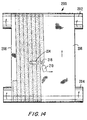
- FIG 14 is a plan view of the apparatus used to practice the present method for manufacturing the belts.
- the apparatus 200 comprises a first roll 202 and a second roll 204, each of which has a smooth and polished surface. These surfaces may be coated with a material, such as polyethylene, polytetrafluoroethylene (PTFE) or silicone, which will readily release a polymeric resin material cured thereon.
- a material such as polyethylene, polytetrafluoroethylene (PTFE) or silicone, which will readily release a polymeric resin material cured thereon.
- a base fabric 206 of one of the constructions set forth above, is disposed about the first and second rolls 202,204, which are then separated from one another to place the base fabric 206 in a taut condition.
- a dispenser 210 applies polymeric resin onto the base fabric 206, which, as described above, has an open area sufficiently high to allow the polymeric resin to flow unimpeded therethrough.
- the first and second rolls 202,204 are rotated in a common direction to move the base fabric 206 along beneath the dispenser 210.
- the dispenser 210 is translated transversely across the base fabric 206. The speeds at which the base fabric 206 and dispenser 210 are moved are preselected so that the base fabric 206 will be completely covered by the polymeric resin in a closed spiral in a single pass. In other words, the base fabric 206 is coated by the polymeric resin in a single pass spiral (SPS) coating process.
- SPS single pass spiral
- the polymeric resin impregnates the base fabric 206, and renders the belt being manufactured impervious to oil and water.
- the polymeric resin may be polyurethane, and preferably is a 100% solids composition thereof.
- the use of a 100% solids resin system which by definition lacks a solvent material, enables one to avoid the formation of bubbles in the polymeric resin during the curing process through which it proceeds following its application onto the base fabric 206.
- the openness of the base fabric 206 and the viscosity of the polymeric resin at the point of application are important factors. That is to say, the openness of the base fabric 206 must be sufficiently high, and the viscosity of the resin sufficiently low, to enable the polymeric resin to penetrate readily through the base fabric 206 without entrapping air bubbles.
- FIG 15 is a side view of apparatus 200 taken from the right-hand side of the plan view given in Figure 14.
- the apparatus 200 further comprises, within the endless loop formed by base fabric 206, a conveyor belt 212 disposed about a third roll 214 and a fourth roll 216.
- the conveyor belt 212 is driven to run at the same speed as base fabric 206, and is parallel thereto, separated therefrom by an amount equal to the thickness of the layer of polymeric resin desired on the inside of the belt being manufactured.
- the conveyor belt 212 like the first and second rolls 202,204, may be coated with a material, such as polyethylene, polytetrafluoroethylene (PTFE) or silicone, which will readily release a polymeric resin material cured thereon.
- PTFE polytetrafluoroethylene
- the dispenser 210 applies the polymeric resin to the base fabric 206 at a point near the beginning of the run of the conveyor belt 212 therebeneath; that is, the polymeric resin is applied at a point reasonably close to third roll 214.
- the common speed of the base fabric 206 and conveyor belt 212 are preselected so that the polymeric resin will cross-link to the "green state", where it has cured to a point where it will no longer flow as a liquid, in a time less than that needed for a given point on the conveyor belt 212 to travel from the third roll 214 to the fourth roll 216.
- the polymeric resin will cross-link to the "green state” before separating from the conveyor belt 212 at fourth roll 216 where it would otherwise be able to flow or drip from the base fabric 206 and the conveyor belt 212.
- the time required for the polymeric resin to cross-link to the "green state” ultimately determines the speed of the coating process, that is, the common speed at which the base fabric 206 and the conveyor belt 212 are run.
- the flow rate of the stream 218 of polymeric resin can be controlled merely to penetrate the base fabric 206 and to provide a layer on the inside thereof; or to provide a layer on the inside of the base fabric 206, to fill the voids in the base fabric 206, and, possibly, to provide a layer of polymeric resin on the outside of the base fabric 206.
- two streams of polymeric resin can be applied onto the base fabric 206 from two dispensers 210, one stream being applied over the other.
- the first stream of polymeric resin may provide sufficient resin to penetrate the base fabric 206 and to form a layer on the inside thereof down to the surface of the conveyor belt 212.
- the first stream may also fill the base fabric 206, and form a thin layer on the outside thereof.
- the second stream of polymeric resin may then provide a layer on the outside of the base fabric 206 and coating formed by the first stream of polymeric resin.
- the first stream can be of one polymeric resin and the second stream can be of another polymeric resin. This is desirable where the coatings on each side of the belts being manufactured are required to have different hardnesses, such as is the case with an LNP belt having grooves or holes on its outer surface or with a calender belt.
- the two dispensers when two dispensers are being used to apply first and second streams of polymeric resin, the two dispensers may be aligned with one another in the cross-machine direction (CD) or in the machine direction (MD), or the two dispensers may be staggered relative to one another in both MD and CD. In this manner, the layering, bonding and mixing of the polymeric resins in the two streams can be controlled.
- a dispenser 210 may first apply a desired amount of a first stream of polymeric resin onto base fabric 206 across its full width, and then a second dispenser 210 may apply a desired amount of a second stream of polymeric resin on top of that left by the first stream in a spiral opposite in direction to that of the first stream.
- Figure 16 is a cross-sectional view taken as indicated by line 16-16 in Figure 15.
- the separation between the base fabric 206 and the conveyor belt 212 determines the thickness of the layer of polymeric resin provided on the inside of the base fabric 206.
- a sidewall 220 which, together with the conveyor belt 212 and the ribbon 222 of polymeric resin from the previous spiral pass of the SPS coating process, forms a mold for the polymeric resin being applied by dispenser 210, prevents the polymeric resin from escaping laterally, or toward the right in Figure 16. As such, sidewall 220 contacts the inside of the base fabric 206.
- the separation between the base fabric 206 and the conveyor belt 212 may be varied to provide layers of different thickness on the inside of the base fabric 206, or to adjust the thickness of the layer during the coating process, while the contact between the sidewall 220 and the base fabric 206 is maintained.
- a contact roll 224 may be used to ensure that the ribbon 222 of polymeric resin from the previous spiral pass presses against the conveyor belt 212 and maintains contact therewith, so that the layer of polymeric resin on the inside of the base fabric 206 will be of uniform thickness.
- a barrier-like sidewall 220 may be used to prevent the polymeric resin from escaping laterally, that is, toward the left in Figure 16.
- the dispenser 210 is translated transversely across the base fabric 206 during the coating process.
- conveyor belt 212, sidewall 220 and contact roll 224 are so translated with the dispenser 210.
- dispenser 210, conveyor belt 212, sidewall 220 and contact roll 224 are mounted in such a way that they may be translated across the base fabric 206 during the coating process by a single drive system.
- Figure 17 is a cross-sectional view of belt 16 taken as indicated by line 17-17 in Figure 2.
- the cross section is taken in the transverse, or cross-machine, direction of belt 16, and shows that belt 16 includes a base fabric 92 of the variety shown in Figures 5 and 6. That is, base fabric 92 is woven in an endless leno weave from warp yarns 94,96 and weft yarns 98. Warp yarns 94,96, viewed from the side in Figure 15, are in the cross-machine direction of the belt 16; weft yarns 98, seen in cross section, are in the machine direction of the belt 16. Crossing points 100, where warp yarns 96 weave over weft yarns 98, may be visible on the outer surface 30 of belt 16, also known as the felt side of belt 16.
- the inner surface 28 of belt 16 is formed by a polymeric resin coating 102.
- the polymeric resin 102 impregnates the base fabric 92, and renders the belt 16 impervious to oil and water.
- Belt 16 is produced using apparatus 200 shown in Figures 14, 15 and 16, wherein stream 218 is controlled to provide a layer of polymeric resin 102 on the inside of the base fabric 92, to fill the voids in the base fabric 92, and to provide a layer of polymeric resin 102 covering crossing points 100 on the outside of base fabric 92.
- polymeric resin 102 After polymeric resin 102 is cured, it may be ground and polished to provide it with a smooth surface and the belt 16 with a uniform thickness.
- any polymeric resin coating on the outside of the belt may be provided with grooves, blind-drilled holes, indentations or the like in some geometric pattern to provide a sink for the temporary storage of water pressed from fibrous web 20 in the press nip 10.
- the polymeric resin coating on the outside of the belt may be the same or different from that on the inside of the belt, as discussed above.
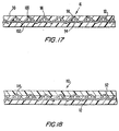
- Figure 18 is a cross-sectional view, analogous to that given in Figure 17, for a belt 110 having a coating of a first polymeric resin 112 on the inside of base fabric 92, and a coating of a second polymeric resin 114 on the outside of base fabric 92.
- Apparatus 200 is used to manufacture belt 110.
- a first dispenser 210 applies first polymeric resin 112 onto base fabric 92 in an amount sufficient to penetrate base fabric 92 and to form a layer on the inside thereof down to the surface of the conveyor belt 212 and to fill the base fabric 92.
- a second dispenser 210 applies second polymeric resin 114 in an amount sufficient to cover the first polymeric resin 112 and base fabric 92 and to form a layer of second polymeric resin 114 thereover.
- First and second polymeric resins 112,114 both render the belt 110 impervious to oil and water. After first and second polymeric resins 112,114 have been cured, second polymeric resin 114 may be ground and polished to provide it with a smooth surface and the belt 110 with a uniform thickness.
- Figure 19 is a cross-sectional view of belt 32 taken as indicated by line 19-19 in Figure 3.
- Belt 32 is constructed in the same manner as belt 110 of Figure 18.
- first and second polymeric resins 112,114 have been cured, and second polymeric resin 114 ground and polished to provide it with a smooth surface and belt 32 with a uniform thickness, grooves 38 may be cut into the outer surface 36 of belt 32.
- the layer of second polymeric resin 114 should be of a thickness sufficient to enable grooves 38 to be cut without reaching base fabric 92.
- Figure 20 is a cross-sectional view of belt 40 taken as indicated by line 20-20 in Figure 4.
- Belt 40 is also constructed in the same manner as belt 110 of Figure 18. After first and second polymeric resins 112,114 have been cured, and second polymeric resin 114 ground and polished to provide it with a smooth surface and belt 40 with a uniform thickness, blind-drilled holes 46 may be drilled into the outer surface 44 of belt 40. It will again be clear to those of ordinary skill in the art that the layer of second polymeric resin 112 should be of a thickness sufficient to enable blind-drilled holes 46 to be drilled without reaching base fabric 92.
- belts 110,32,40 shown in cross section in Figures 18, 19 and 20, respectively, may be manufactured using only one polymeric resin, rather than two, that is, rather than a first and second polymeric resin 112,114.
- the polymeric resin penetrates the base fabric 92 to provide a layer on the inside thereof, to fill the voids therein, and to provide a layer on the outside thereof of sufficient thickness to enable grooves 38 to be cut or blind-drilled holes 46 to be drilled without reaching base fabric 92.
- the polymeric resins used in the practice of the present invention are preferably of the reactive type, either chemically cross-linked with a catalyst or cross-linked with the application of heat. Resins having a 100% solids composition, that is, lacking a solvent, are preferred, as solvents tend to generate bubbles during the curing process. Polyurethane resins having 100% solids compositions are preferred.
- the apparatus 200 used in the practice of the present invention enables a smooth layer of polymeric resin to be disposed on the inside of a paper processing belt without the necessity of inverting (turning inside out) the belt at any time during the manufacturing process.
- the polymeric resin will tend to stick to the conveyor belt 212, it may be desirable to provide the belt 212 with a coating to facilitate the removal of the belt therefrom.
- Polyethylene, polytetrafluoro-ethylene (PTFE) or silicone may be used for this purpose.
- the lateral edges of the belt so obtained may be trimmed parallel to the machine direction to remove non-uniformities along the edges and to give the belt a desired, finished width.
Landscapes
- Engineering & Computer Science (AREA)
- Mechanical Engineering (AREA)
- Textile Engineering (AREA)
- Chemical & Material Sciences (AREA)
- Composite Materials (AREA)
- Manufacturing & Machinery (AREA)
- Paper (AREA)
- Woven Fabrics (AREA)
- Knitting Of Fabric (AREA)
- Reinforced Plastic Materials (AREA)
Applications Claiming Priority (2)
| Application Number | Priority Date | Filing Date | Title |
|---|---|---|---|
| US386114 | 1989-07-28 | ||
| US09/386,114 US6231928B1 (en) | 1999-08-30 | 1999-08-30 | Method for manufacturing resin-impregnated endless belt structures for papermaking machines and similar industrial applications |
Publications (2)
| Publication Number | Publication Date |
|---|---|
| EP1081275A2 true EP1081275A2 (fr) | 2001-03-07 |
| EP1081275A3 EP1081275A3 (fr) | 2001-10-24 |
Family
ID=23524219
Family Applications (1)
| Application Number | Title | Priority Date | Filing Date |
|---|---|---|---|
| EP00102182A Withdrawn EP1081275A3 (fr) | 1999-08-30 | 2000-02-09 | Procédé de fabrication d'une bande sans fin pour machines à papier |
Country Status (13)
| Country | Link |
|---|---|
| US (1) | US6231928B1 (fr) |
| EP (1) | EP1081275A3 (fr) |
| JP (1) | JP3524046B2 (fr) |
| KR (1) | KR100518118B1 (fr) |
| CN (1) | CN1185385C (fr) |
| AU (1) | AU730658B1 (fr) |
| BR (1) | BR0001340A (fr) |
| CA (1) | CA2308011C (fr) |
| ID (1) | ID27100A (fr) |
| MX (1) | MXPA00007574A (fr) |
| NO (1) | NO319124B1 (fr) |
| TW (1) | TW548364B (fr) |
| ZA (1) | ZA200000237B (fr) |
Cited By (7)
| Publication number | Priority date | Publication date | Assignee | Title |
|---|---|---|---|---|
| WO2003103934A1 (fr) * | 2002-06-11 | 2003-12-18 | ヤマウチ株式会社 | Courroie elastique industrielle et procede de fabrication |
| WO2004110729A3 (fr) * | 2003-05-23 | 2005-02-17 | Albany Int Corp | Courroie ou rouleau a surface rainuree, et procede de fabrication |
| WO2009077216A1 (fr) * | 2007-12-19 | 2009-06-25 | Voith Patent Gmbh | Bande transporteuse et son procédé de fabrication |
| RU2422568C1 (ru) * | 2010-05-05 | 2011-06-27 | Василий Юльевич Жиркевич | Сетчатая оболочка |
| WO2015091654A1 (fr) * | 2013-12-20 | 2015-06-25 | Voith Patent Gmbh | Enveloppe de compression ou bande de traitement pour une machine de fabrication et/ou de traitement d'une bande fibreuse |
| WO2017046128A1 (fr) * | 2015-09-18 | 2017-03-23 | Voith Patent Gmbh | Chemise de presse et procédé de fabrication associé |
| WO2021058171A1 (fr) * | 2019-09-27 | 2021-04-01 | Voith Patent Gmbh | Chemise de presse, son utilisation, rouleau de presse et presse à sabot |
Families Citing this family (10)
| Publication number | Priority date | Publication date | Assignee | Title |
|---|---|---|---|---|
| US6946163B2 (en) * | 2001-08-31 | 2005-09-20 | Honda of Canada Manufacturing a division of Honda Canada Inc. | Coating technique |
| US6989080B2 (en) * | 2003-06-19 | 2006-01-24 | Albany International Corp. | Nonwoven neutral line dryer fabric |
| US8840683B2 (en) * | 2003-11-19 | 2014-09-23 | Albany International Corp. | Industrial textile fabric |
| US7654296B2 (en) * | 2003-11-24 | 2010-02-02 | Albany International Corp. | Grooved single facer belt |
| ATE477289T1 (de) * | 2004-03-16 | 2010-08-15 | Albany Int Corp | Polyurethanbeschichtete bänder mit nanofüllstoffen |
| DK1791997T3 (da) * | 2004-08-31 | 2012-08-13 | Obermeyer Henry K | Højstyrkeforbindelsessystem til fiberforstærkede kompositmaterialer |
| DE102004054804A1 (de) * | 2004-11-12 | 2006-05-18 | Voith Fabrics Patent Gmbh | Papiermaschinenbespannung |
| JP5270834B2 (ja) | 2006-12-22 | 2013-08-21 | ヤマウチ株式会社 | 製紙用ベルト |
| US7712336B2 (en) * | 2007-01-31 | 2010-05-11 | Albany International Corp. | Subassembly for industrial fabrics |
| EP3913131B1 (fr) * | 2020-05-20 | 2024-11-13 | Valmet Technologies Oy | Bande pour un rouleau à bande et son utilisation |
Family Cites Families (9)
| Publication number | Priority date | Publication date | Assignee | Title |
|---|---|---|---|---|
| LU68838A1 (fr) * | 1973-11-21 | 1975-08-20 | ||
| FR2494318B1 (fr) | 1980-11-14 | 1986-10-10 | Feutres Papeteries Tissus Indl | Bande constituee de spirales |
| US5238537A (en) | 1981-09-15 | 1993-08-24 | Dutt William H | Extended nip press belt having an interwoven base fabric and an impervious impregnant |
| US4552620A (en) * | 1983-09-19 | 1985-11-12 | Beloit Corporation | Paper machine belt |
| US5062924A (en) * | 1988-04-08 | 1991-11-05 | Beloit Corporation | Blanket for an extended nip press with anisotropic woven base layers |
| US5171389A (en) * | 1991-11-08 | 1992-12-15 | Albany International Corp. | Spiral construction of grooved long nip press |
| EP0658649A1 (fr) * | 1993-12-14 | 1995-06-21 | Appleton Mills | Bande ou enveloppe pour presse comportant, comme tissu de base, un tissu en hélices combinées, pour utilisation dans une presse à pinçage prolongé |
| US5772848A (en) * | 1996-12-03 | 1998-06-30 | Albany International Corp. | Braided base fabrics for shoe press belts |
| US6174825B1 (en) * | 1997-12-09 | 2001-01-16 | Albany International Corp. | Resin-impregnated belt for application on papermaking machines and in similar industrial application |
-
1999
- 1999-08-30 US US09/386,114 patent/US6231928B1/en not_active Expired - Fee Related
-
2000
- 2000-01-14 AU AU10093/00A patent/AU730658B1/en not_active Ceased
- 2000-01-20 ZA ZA200000237A patent/ZA200000237B/xx unknown
- 2000-02-09 EP EP00102182A patent/EP1081275A3/fr not_active Withdrawn
- 2000-02-28 CN CNB001036025A patent/CN1185385C/zh not_active Expired - Fee Related
- 2000-03-10 KR KR10-2000-0011932A patent/KR100518118B1/ko not_active Expired - Fee Related
- 2000-03-16 BR BR0001340-4A patent/BR0001340A/pt not_active IP Right Cessation
- 2000-05-03 TW TW089108414A patent/TW548364B/zh not_active IP Right Cessation
- 2000-05-11 CA CA002308011A patent/CA2308011C/fr not_active Expired - Fee Related
- 2000-08-02 MX MXPA00007574A patent/MXPA00007574A/es active IP Right Grant
- 2000-08-28 JP JP2000257378A patent/JP3524046B2/ja not_active Expired - Fee Related
- 2000-08-29 NO NO20004301A patent/NO319124B1/no unknown
- 2000-08-30 ID IDP20000723D patent/ID27100A/id unknown
Cited By (10)
| Publication number | Priority date | Publication date | Assignee | Title |
|---|---|---|---|---|
| WO2003103934A1 (fr) * | 2002-06-11 | 2003-12-18 | ヤマウチ株式会社 | Courroie elastique industrielle et procede de fabrication |
| WO2004110729A3 (fr) * | 2003-05-23 | 2005-02-17 | Albany Int Corp | Courroie ou rouleau a surface rainuree, et procede de fabrication |
| US7374640B2 (en) | 2003-05-23 | 2008-05-20 | Albany International Corp. | Grooved surface belt or roll and method of fabrication |
| WO2009077216A1 (fr) * | 2007-12-19 | 2009-06-25 | Voith Patent Gmbh | Bande transporteuse et son procédé de fabrication |
| US8500958B2 (en) | 2007-12-19 | 2013-08-06 | Voith Patent Gmbh | Belt and method to manufacture |
| CN101946039B (zh) * | 2007-12-19 | 2015-05-20 | 沃依特专利有限责任公司 | 传送带和制造该传送带的方法 |
| RU2422568C1 (ru) * | 2010-05-05 | 2011-06-27 | Василий Юльевич Жиркевич | Сетчатая оболочка |
| WO2015091654A1 (fr) * | 2013-12-20 | 2015-06-25 | Voith Patent Gmbh | Enveloppe de compression ou bande de traitement pour une machine de fabrication et/ou de traitement d'une bande fibreuse |
| WO2017046128A1 (fr) * | 2015-09-18 | 2017-03-23 | Voith Patent Gmbh | Chemise de presse et procédé de fabrication associé |
| WO2021058171A1 (fr) * | 2019-09-27 | 2021-04-01 | Voith Patent Gmbh | Chemise de presse, son utilisation, rouleau de presse et presse à sabot |
Also Published As
| Publication number | Publication date |
|---|---|
| NO20004301L (no) | 2001-03-01 |
| CA2308011A1 (fr) | 2001-02-28 |
| EP1081275A3 (fr) | 2001-10-24 |
| KR20010020656A (ko) | 2001-03-15 |
| CN1185385C (zh) | 2005-01-19 |
| ZA200000237B (en) | 2001-05-30 |
| CA2308011C (fr) | 2004-11-02 |
| NO319124B1 (no) | 2005-06-20 |
| MXPA00007574A (es) | 2002-03-26 |
| AU730658B1 (en) | 2001-03-08 |
| ID27100A (id) | 2001-03-01 |
| BR0001340A (pt) | 2001-04-03 |
| CN1286331A (zh) | 2001-03-07 |
| JP3524046B2 (ja) | 2004-04-26 |
| TW548364B (en) | 2003-08-21 |
| US6231928B1 (en) | 2001-05-15 |
| KR100518118B1 (ko) | 2005-10-04 |
| JP2001089991A (ja) | 2001-04-03 |
| NO20004301D0 (no) | 2000-08-29 |
Similar Documents
| Publication | Publication Date | Title |
|---|---|---|
| EP0922806B1 (fr) | Bande imprégnée de résine pour l'utilisation dans des machines à papier et autres appplications industrielles similaires | |
| CA2061804C (fr) | Methode de renforcement des bandes presseuses a longues surfaces de contact | |
| EP1087056B1 (fr) | Supports pour bandes revêtues | |
| US6231928B1 (en) | Method for manufacturing resin-impregnated endless belt structures for papermaking machines and similar industrial applications | |
| CA2245734C (fr) | Tissus a base de structure tressee destines aux courroies pour presses a patins | |
| NZ519892A (en) | Grooved long nip shoe press belt | |
| US20050115100A1 (en) | Belt with variable grooves | |
| US7011730B2 (en) | Structure for process belt | |
| US7374640B2 (en) | Grooved surface belt or roll and method of fabrication |
Legal Events
| Date | Code | Title | Description |
|---|---|---|---|
| PUAI | Public reference made under article 153(3) epc to a published international application that has entered the european phase |
Free format text: ORIGINAL CODE: 0009012 |
|
| AK | Designated contracting states |
Kind code of ref document: A2 Designated state(s): AT BE CH CY DE DK ES FI FR GB GR IE IT LI LU MC NL PT SE |
|
| AX | Request for extension of the european patent |
Free format text: AL;LT;LV;MK;RO;SI |
|
| PUAL | Search report despatched |
Free format text: ORIGINAL CODE: 0009013 |
|
| 17P | Request for examination filed |
Effective date: 20010820 |
|
| AK | Designated contracting states |
Kind code of ref document: A3 Designated state(s): AT BE CH CY DE DK ES FI FR GB GR IE IT LI LU MC NL PT SE |
|
| AX | Request for extension of the european patent |
Free format text: AL;LT;LV;MK;RO;SI |
|
| AKX | Designation fees paid |
Free format text: AT BE CH CY DE DK ES FI FR GB GR IE IT LI LU MC NL PT SE |
|
| GRAP | Despatch of communication of intention to grant a patent |
Free format text: ORIGINAL CODE: EPIDOSNIGR1 |
|
| STAA | Information on the status of an ep patent application or granted ep patent |
Free format text: STATUS: THE APPLICATION HAS BEEN WITHDRAWN |
|
| 18W | Application withdrawn |
Effective date: 20060314 |