EP1081277A2 - Machine pour production et/ou traitement d'une bande - Google Patents
Machine pour production et/ou traitement d'une bande Download PDFInfo
- Publication number
- EP1081277A2 EP1081277A2 EP00111355A EP00111355A EP1081277A2 EP 1081277 A2 EP1081277 A2 EP 1081277A2 EP 00111355 A EP00111355 A EP 00111355A EP 00111355 A EP00111355 A EP 00111355A EP 1081277 A2 EP1081277 A2 EP 1081277A2
- Authority
- EP
- European Patent Office
- Prior art keywords
- machine according
- sealing
- hood
- material web
- overpressure
- Prior art date
- Legal status (The legal status is an assumption and is not a legal conclusion. Google has not performed a legal analysis and makes no representation as to the accuracy of the status listed.)
- Granted
Links
Images



Classifications
-
- D—TEXTILES; PAPER
- D21—PAPER-MAKING; PRODUCTION OF CELLULOSE
- D21F—PAPER-MAKING MACHINES; METHODS OF PRODUCING PAPER THEREON
- D21F5/00—Dryer section of machines for making continuous webs of paper
- D21F5/02—Drying on cylinders
-
- D—TEXTILES; PAPER
- D21—PAPER-MAKING; PRODUCTION OF CELLULOSE
- D21F—PAPER-MAKING MACHINES; METHODS OF PRODUCING PAPER THEREON
- D21F5/00—Dryer section of machines for making continuous webs of paper
- D21F5/004—Drying webs by contact with heated surfaces or materials
-
- D—TEXTILES; PAPER
- D21—PAPER-MAKING; PRODUCTION OF CELLULOSE
- D21F—PAPER-MAKING MACHINES; METHODS OF PRODUCING PAPER THEREON
- D21F5/00—Dryer section of machines for making continuous webs of paper
- D21F5/02—Drying on cylinders
- D21F5/04—Drying on cylinders on two or more drying cylinders
- D21F5/042—Drying on cylinders on two or more drying cylinders in combination with suction or blowing devices
- D21F5/044—Drying on cylinders on two or more drying cylinders in combination with suction or blowing devices using air hoods over the cylinders
-
- F—MECHANICAL ENGINEERING; LIGHTING; HEATING; WEAPONS; BLASTING
- F26—DRYING
- F26B—DRYING SOLID MATERIALS OR OBJECTS BY REMOVING LIQUID THEREFROM
- F26B13/00—Machines and apparatus for drying fabrics, fibres, yarns, or other materials in long lengths, with progressive movement
- F26B13/10—Arrangements for feeding, heating or supporting materials; Controlling movement, tension or position of materials
- F26B13/14—Rollers, drums, cylinders; Arrangement of drives, supports, bearings, cleaning
- F26B13/18—Rollers, drums, cylinders; Arrangement of drives, supports, bearings, cleaning heated or cooled, e.g. from inside, the material being dried on the outside surface by conduction
-
- F—MECHANICAL ENGINEERING; LIGHTING; HEATING; WEAPONS; BLASTING
- F26—DRYING
- F26B—DRYING SOLID MATERIALS OR OBJECTS BY REMOVING LIQUID THEREFROM
- F26B13/00—Machines and apparatus for drying fabrics, fibres, yarns, or other materials in long lengths, with progressive movement
- F26B13/24—Arrangements of devices using drying processes not involving heating
- F26B13/26—Arrangements of devices using drying processes not involving heating using sorbent surfaces, e.g. bands or coverings on rollers
-
- F—MECHANICAL ENGINEERING; LIGHTING; HEATING; WEAPONS; BLASTING
- F26—DRYING
- F26B—DRYING SOLID MATERIALS OR OBJECTS BY REMOVING LIQUID THEREFROM
- F26B13/00—Machines and apparatus for drying fabrics, fibres, yarns, or other materials in long lengths, with progressive movement
- F26B13/24—Arrangements of devices using drying processes not involving heating
- F26B13/28—Arrangements of devices using drying processes not involving heating for applying pressure; for brushing; for wiping
Definitions
- the invention relates to a machine for manufacturing and / or treatment a material web, in particular paper or cardboard web, with at least a heatable unit, in particular a press roll, a Drying cylinders and / or the like on part of their outer circumference of the material web, at least one sieve and an outer one Sealing tape is wrapped around, and one with a heated unit pressurized liquid or gaseous medium Overpressure hood.
- the aim of the invention is to make a machine of the type mentioned at the beginning create, in the simplest possible way on the one hand from the material web and the area occupied by the at least one sieve or felt reliable compared to the pressure chamber of the overpressure hood and on the other hand, this pressure chamber is reliably sealed to the outside.
- the sealing tape is wider than the material web and the sieve and with its two lateral edge areas protrudes beyond this, so that its two Edge areas due to the prevailing in the pressure chamber of the pressure hood Sealing overpressure to the surface of the heatable unit be pressed, and / or that the pressure chamber of the pressure hood at both ends with a seal to the outside is sealed between an end wall of the fixed pressure hood and an in particular radial counter wall on the cylinder side is arranged.
- the pressurized liquid or gaseous medium can it is in particular a cooling medium. Because the Temperature of the liquid or gaseous medium is lower than that Temperature on the outside of the web and screen wrapped part of the circumference of the heatable element, a high Liquid discharge from the material web can be achieved. It can be a or several sieves can be provided, in which case it is possible is that a screen located further out has a coarser structure than a sieve inside. In the case of multiple screens, you can these are separated from one another or at least partially with one another be connected. The sealing tape can be provided separately or with at least be connected to a sieve belt.
- the material web and the strainer provided in an outer periphery of the heatable unit Well arranged is wider than this Depression and with its two lateral edge areas over this protrudes.
- the height of the depression can be at least essentially equal to the total height of the material web and the sieve.
- edges or side walls of the depression thanks to a heat-resistant, flexible and well-sealing material such as in particular Teflon, silicone or the like are coated.
- a heat-resistant, flexible and well-sealing material such as in particular Teflon, silicone or the like are coated.
- At least one respective side Edge area of the sealing tape opposite and covered by this Sealing pocket or chamber can be provided.
- the sealing surface can be ensured. Occurs as a result of a coolant failure into a sealing pocket or chamber, this liquid will pass through the connection channel or holes in question, which can serve as an indicator of leakage.
- the at least one counter wall on the cylinder side can expediently by a disk arranged at the respective end of the heatable unit be educated.
- the sealing force can be achieved, for example, by the preload the pressure hood due to the internal pressure or also mechanically be applied. When generating the sealing force the overpressure hood is pressed against the pane, and the seal automatically receives a prestress corresponding to the pressure.
- the preload is regulated when the internal pressure changes the poetry by itself.
- At least one is on the cylinder side Counter wall by one in the area of a respective journal the heated unit provided shoulder and the respective Front wall of the overpressure hood up to the area of this bearing journal guided.
- the seal can, for example, in the area of the bearing journal or be somewhere halfway there. Also in this The sealing force can fall again due to the pretensioning of the hood internal pressure or mechanically applied. Because the respective counter wall and the seal arranged in the region of the bearing journal are, the relative speed between rotating and fixed part less, which causes wear of the seal accordingly is reduced.
- At least one end face of the heatable unit is advantageously included provided with a heat-resistant material, which the direct heat flow between the hot unit and the cold cooling medium minimizes.
- At least one between an end wall of the fixed pressure hood and a cylinder side Opposite wall arranged seal between an end wall and the counter wall arranged resilient element is.
- This can be, in particular, a mechanical element act, for example, at least one spring.
- the pressure chamber of the overpressure hood can also be at least a non-contact seal such as a labyrinth seal or the like to be sealed to the outside.
- the heatable unit can also be used as a shoe press replacement, for example very long nip length can be provided.
- the material web 14 can in particular be a Trade paper or cardboard web.
- the drying cylinder 10 is both from the material web 14 as well as from at least one sieve, in the present case Case two sieves 16, 18, and an outer sealing tape 20 wrapped around.
- Das der Material web 14 adjacent screen 16 can have a finer structure than the screen 18 adjacent to the sealing tape 20.
- the heatable, rotating Drying cylinder 10 with a pressurized liquid or gaseous Medium which is in particular a Coolant can act so that from the drying cylinder 10 to the sealing tape 20 a temperature gradient arises.
- a pressurized liquid or gaseous Medium which is in particular a Coolant
- the heatable, rotating Drying cylinder 10 with a pressurized liquid or gaseous Medium which is in particular a Coolant can act so that from the drying cylinder 10 to the sealing tape 20 a temperature gradient arises.
- a pressure drop in the other Direction is generated and the material web accordingly with the outer belt is in contact.
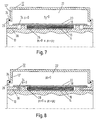
- Pressure chamber 22 of the overpressure hood 12 there is a pressure p before, which is greater than the ambient pressure or atmospheric pressure.
- the sealing tape 20th is in each case wider than the material web 14 and the two screens 16, 18 and protrudes beyond it with its two lateral edge areas.
- the two edge areas of the sealing tape 20 by the in the pressure chamber 22 of the overpressure hood prevailing overpressure p sealingly pressed against the surface of the drying cylinder 10.
- the of the material web 14 and the two screens 16, 18 occupied area is thus made impermeable to liquids and / or gases Sealing tape 20 sealed.
- the pressure chamber 22 of the overpressure hood 12 is on its two end faces each sealed by a seal 24 to the outside, which between the relevant end wall 12 'of the fixed pressure hood 12 and an in particular radial cylinder-side counter wall 26 in the area of the respective drying cylinder end is arranged.
- the Material web 14 and the screens 16, 18 in one on the outer circumference of the Drying cylinder 10 provided recess 28 arranged.
- the sealing tape 20 is wider than this recess 28, being with both lateral Border areas protrude beyond this. It has to be stiff enough so that it is not drawn into the recess.
- the height of the depression 28 is preferably at least substantially equal to the total height of the material web 14 and the sieves 16, 18.
- the depression receiving the material web 14 and the screens 167, 18 28 is consequently due to that with its edge regions on the drying cylinder 10 pressed sealing tape against the pressure chamber 22 of the pressure hood 12 sealed.
- the two are on the cylinder side Counter walls 26 each by one in the area of a respective one Bearing pin 30 of the drying cylinder 10 provided shoulder formed.
- the end walls 12 'of the pressure hood 12 are in the range of Bearing journal 30 guided.
- the seals 24 are in the range of each Bearing pin 30 between the respective end wall 12 'and the relevant one Shoulder arranged.
- the pressure chamber 22 of the pressure chamber is in these in FIGS. 1 to 3 illustrated embodiments laterally each up to the bearing journal 30 led. Due to the overpressure in the pressure chamber 22 of the overpressure hood 12 can thus the end walls 12 'against the cylinder side Counter walls 26 or shoulders are pressed, causing the seals 24 receive a prestress corresponding to this pressure. At The preload is regulated by a respective change in the internal pressure the seals 24 by themselves.
- the between a respective end wall 12 'of the fixed pressure hood 12 and a respective counter wall 26 on the cylinder side Seals 24 also have a between the end wall 12 'and the counter wall 26 arranged, in particular mechanical, resilient element 32 be loaded with, for example, at least one spring 32 '.
- the respective spring 32 ' can an axially displaceable stop 32 ′′ on the relevant seal 24 Act.
- the resilient elements 32 are non-rotatable with the pressure hood 12 connected, i.e. they do not rotate with the drying cylinder 10.
- the Seals 24 are thus between a rotating and a non-rotating Part arranged.
- the two sealing pockets or chambers 34 are each over at least a channel 36 or at least one bore connected to the environment, so that they are under ambient or atmospheric pressure.
- the Recess 28 also several sealing pockets or chambers 34 are provided his.
- the respective three sealing pockets or chambers 34 is the axially outer one connected to the environment via at least one channel 36.
- the two are on the cylinder side radial counter walls 26 each by one on the respective Drying cylinder end arranged disc formed.
- the pressure p 1 in the depression 28 is higher than the ambient or atmospheric pressure, but lower than the pressure p 2 in the pressure chamber 22 of the pressure hood 12.
- the end faces of the drying cylinder 10 with be provided with a heat-resistant material.
- the material web 14, the Sieves 16, 18 and the sealing tape 20 also over one in the area in question be flat drying cylinder 10 without a recess. Also in in this case, the one taken up by the material web 14 and the screens 16, 18 Area through the sealing tape 20 opposite the pressure chamber 22 of the pressure hood 12 sealed by its protruding Edge areas against the excess pressure in the pressure chamber 22 the cylinder surface are pressed.
- the edges or side walls the recess 28 by a heat-resistant, flexible and well sealing Material D such as in particular Teflon, silicone or the like coated.
- the pressure chamber 22 of the overpressure hood 12 for example also by at least one non-contact seal such as in particular a labyrinth seal or the like sealed to the outside his.
- the drying cylinder can also be equipped with an appropriate one heat-resistant, well-sealing material.
- the same thing also applies to the sealing tape.
- the one through the first Chamber penetrated liquid is through the or those concerned Channels are discharged, which serve as an indicator of a respective leak can.
- the sealing of the Space between the hot cylinder and the material web clearly be improved.
- the resulting steam pressure increases. Accordingly, a larger one Water quantity pushed out of the material web and the drying performance improved with the same heating output. Is the sealing of the Pressure chamber in the area of the bearing journal, this results in a lower relative speed between the rotating and stationary parts, whereby the wear of the seals is reduced accordingly.
- the dryer section in question can be designed in this way, for example be as described in DE 197 23 163 A1.
Landscapes
- Engineering & Computer Science (AREA)
- Textile Engineering (AREA)
- Mechanical Engineering (AREA)
- General Engineering & Computer Science (AREA)
- Drying Of Solid Materials (AREA)
- Paper (AREA)
Applications Claiming Priority (2)
| Application Number | Priority Date | Filing Date | Title |
|---|---|---|---|
| DE19941334A DE19941334A1 (de) | 1999-08-31 | 1999-08-31 | Maschine zur Herstellung und/oder Behandlung einer Materialbahn |
| DE19941334 | 1999-08-31 |
Publications (3)
| Publication Number | Publication Date |
|---|---|
| EP1081277A2 true EP1081277A2 (fr) | 2001-03-07 |
| EP1081277A3 EP1081277A3 (fr) | 2001-07-18 |
| EP1081277B1 EP1081277B1 (fr) | 2004-10-13 |
Family
ID=7920228
Family Applications (1)
| Application Number | Title | Priority Date | Filing Date |
|---|---|---|---|
| EP00111355A Expired - Lifetime EP1081277B1 (fr) | 1999-08-31 | 2000-05-26 | Machine pour production et/ou traitement d'une bande |
Country Status (3)
| Country | Link |
|---|---|
| US (1) | US6397493B1 (fr) |
| EP (1) | EP1081277B1 (fr) |
| DE (2) | DE19941334A1 (fr) |
Cited By (4)
| Publication number | Priority date | Publication date | Assignee | Title |
|---|---|---|---|---|
| EP1586701A1 (fr) * | 2004-04-13 | 2005-10-19 | Voith Paper Patent GmbH | Dispositif de séchage |
| WO2005100684A1 (fr) | 2004-04-13 | 2005-10-27 | Voith Patent Gmbh | Dispositif de sechage |
| DE102008042285A1 (de) | 2008-09-23 | 2010-03-25 | Voith Patent Gmbh | Beheizbarer Zylinder zur Aufheizung einer Papier-, Karton-, Tissue- oder anderen Materialbahn |
| EP2186938A1 (fr) | 2008-11-14 | 2010-05-19 | Voith Patent GmbH | Agencement d'étanchéité pour un corps cylindrique, notamment un cylindre de séchage |
Families Citing this family (5)
| Publication number | Priority date | Publication date | Assignee | Title |
|---|---|---|---|---|
| DE10155046A1 (de) * | 2001-11-09 | 2003-05-22 | Voith Paper Patent Gmbh | Luftdurchlässiges Band |
| KR200298008Y1 (ko) * | 2002-08-07 | 2002-12-12 | 주식회사 아이손 | 무게 조절이 가능한 신발 안창 |
| WO2004038093A1 (fr) * | 2002-10-24 | 2004-05-06 | Voith Fabrics Heidenheim Gmbh & Co. Kg. | Tissu de sechage par condensation |
| CN103184704B (zh) * | 2011-12-31 | 2015-05-20 | 广东侨盛防伪材料有限公司 | 电热膜式加热烫平缸 |
| WO2020194360A1 (fr) * | 2019-03-26 | 2020-10-01 | Toscotec S.P.A. | Procédé de fabrication d'un séchoir yankee en acier et séchoir yankee en acier |
Family Cites Families (15)
| Publication number | Priority date | Publication date | Assignee | Title |
|---|---|---|---|---|
| USRE25358E (en) * | 1954-04-15 | 1963-03-26 | Process of and apparatus for papermaking | |
| US2835048A (en) * | 1957-04-04 | 1958-05-20 | Gen Electric | Basket supporting and sealing arrangement for clothes dryers |
| US3040702A (en) * | 1958-06-19 | 1962-06-26 | Nat Res Corp | Vacuum coating apparatus having sealing means formed of membranes and fibers |
| US3058232A (en) * | 1960-01-20 | 1962-10-16 | Nat Res Corp | High vacuum |
| US3048992A (en) * | 1960-06-13 | 1962-08-14 | Nakaguchi Koichi | Apparatus for air-tightly leading textile fabrics into or out of a pressure chamber |
| US3303576A (en) * | 1965-05-28 | 1967-02-14 | Procter & Gamble | Apparatus for drying porous paper |
| US3919783A (en) * | 1971-03-29 | 1975-11-18 | Anthony J Cirrito | Method for hot gas heat transfer, particularly for paper drying |
| GB1519265A (en) * | 1975-04-09 | 1978-07-26 | Valmet Oy | Method and apparatus for treatment of a web in order to adjust the moisture content thereof |
| US4214758A (en) * | 1979-03-12 | 1980-07-29 | Gorodissky Leonid G | Face sealer device for roller lock gates |
| FI61537C (fi) * | 1981-02-19 | 1982-08-10 | Tampella Oy Ab | Foerfarande och anlaeggning foer kontinuerlig torkning av en pappers- eller liknande poroes bana |
| FI87474C (fi) * | 1989-12-01 | 1993-01-11 | Valmet Paper Machinery Inc | Foerfarande och anordning i en pappersmaskin |
| FI86655C (fi) * | 1990-03-16 | 1992-09-25 | Valmet Paper Machinery Inc | Tillslutningskonstruktion foer att anvaendas vid omraodet med enkelt viradrag av torkningsviran i en pappersmaskin eller motsvarande. |
| CA2188969A1 (fr) * | 1995-10-27 | 1997-04-28 | Karl Steiner | Dispositif pour presser la nappe contre les cylindres secheurs |
| DE19607476C1 (de) * | 1996-02-28 | 1997-04-10 | Voith Sulzer Finishing Gmbh | Verfahren zum Satinieren von Papier und Kalander zur Durchführung des Verfahrens |
| DE19723163A1 (de) | 1997-06-03 | 1998-12-10 | Voith Sulzer Papiermasch Gmbh | Trockenpartie |
-
1999
- 1999-08-31 DE DE19941334A patent/DE19941334A1/de not_active Withdrawn
-
2000
- 2000-05-26 DE DE2000508204 patent/DE50008204D1/de not_active Expired - Lifetime
- 2000-05-26 EP EP00111355A patent/EP1081277B1/fr not_active Expired - Lifetime
- 2000-08-23 US US09/643,967 patent/US6397493B1/en not_active Expired - Fee Related
Cited By (5)
| Publication number | Priority date | Publication date | Assignee | Title |
|---|---|---|---|---|
| EP1586701A1 (fr) * | 2004-04-13 | 2005-10-19 | Voith Paper Patent GmbH | Dispositif de séchage |
| WO2005100684A1 (fr) | 2004-04-13 | 2005-10-27 | Voith Patent Gmbh | Dispositif de sechage |
| DE102008042285A1 (de) | 2008-09-23 | 2010-03-25 | Voith Patent Gmbh | Beheizbarer Zylinder zur Aufheizung einer Papier-, Karton-, Tissue- oder anderen Materialbahn |
| EP2186938A1 (fr) | 2008-11-14 | 2010-05-19 | Voith Patent GmbH | Agencement d'étanchéité pour un corps cylindrique, notamment un cylindre de séchage |
| DE102008043744A1 (de) | 2008-11-14 | 2010-05-20 | Voith Patent Gmbh | Dichtanordnung für einen zylinderförmigen Körper, insbesondere einen Trockenzylinder |
Also Published As
| Publication number | Publication date |
|---|---|
| DE50008204D1 (de) | 2004-11-18 |
| DE19941334A1 (de) | 2001-03-01 |
| EP1081277A3 (fr) | 2001-07-18 |
| EP1081277B1 (fr) | 2004-10-13 |
| US6397493B1 (en) | 2002-06-04 |
Similar Documents
| Publication | Publication Date | Title |
|---|---|---|
| DE68929409T2 (de) | Verfahren zum Halten einer Materialbahn auf einem Trockenfilz | |
| EP0988417B1 (fr) | Secherie | |
| DE3102526A1 (de) | Presswalze fuer bandfoermiges gut | |
| DE3800210C2 (de) | Vorrichtung zur Abdichtung einer Druckmedium enthaltenden Kammer | |
| EP1081277B1 (fr) | Machine pour production et/ou traitement d'une bande | |
| EP1081276A2 (fr) | Système de séchage | |
| DE29701986U1 (de) | Saugeinrichtung | |
| DE2818843B2 (de) | Wellendichtung mit einer Dichtungspackung | |
| DE69001674T2 (de) | Geschlossene presseinrichtung mit verlaengerter presszone. | |
| DE69131077T2 (de) | Papiermaschine zum Pressen und Trocknen einer Faserstoffbahn | |
| DE4223715C2 (de) | Walze | |
| DE19633958A1 (de) | Saugpreßwalze | |
| EP1362949B1 (fr) | Procédé et dispositif pour la déshydratation d' une bande fibreuse | |
| DE69003113T2 (de) | Belüftungswalze mit temperaturausgleich. | |
| DE69721830T2 (de) | Verfahren und vorrichtung zur behandlung einer faserbahn | |
| DE29924882U1 (de) | Maschine zur Herstellung und/oder Behandlung einer Materialbahn | |
| EP1586839A2 (fr) | Ensemble d'étanchéité, notamment pour une installation de séchage | |
| DE19617801A1 (de) | Preßvorrichtung | |
| DE9011940U1 (de) | Pressenpartie einer Papiermaschine | |
| DE69712793T2 (de) | Verfahren und vorrichtung zur trocknung einer faserbahn | |
| EP1735551B1 (fr) | Dispositif d'etancheification, en particulier pour dispositif de sechage | |
| DE3604137A1 (de) | Dichtung | |
| DE102007018529A1 (de) | Dichtungsanordnung für eine Trockeneinrichtung in einer Maschine zur Herstellung einer Faserstoffbahn | |
| DE29724839U1 (de) | Trockenpartie | |
| DE29623039U1 (de) | Saugpreßwalze |
Legal Events
| Date | Code | Title | Description |
|---|---|---|---|
| PUAI | Public reference made under article 153(3) epc to a published international application that has entered the european phase |
Free format text: ORIGINAL CODE: 0009012 |
|
| AK | Designated contracting states |
Kind code of ref document: A2 Designated state(s): DE FI SE |
|
| AX | Request for extension of the european patent |
Free format text: AL;LT;LV;MK;RO;SI |
|
| PUAL | Search report despatched |
Free format text: ORIGINAL CODE: 0009013 |
|
| AK | Designated contracting states |
Kind code of ref document: A3 Designated state(s): AT BE CH CY DE DK ES FI FR GB GR IE IT LI LU MC NL PT SE |
|
| AX | Request for extension of the european patent |
Free format text: AL;LT;LV;MK;RO;SI |
|
| 17P | Request for examination filed |
Effective date: 20020118 |
|
| AKX | Designation fees paid |
Free format text: DE FI SE |
|
| 17Q | First examination report despatched |
Effective date: 20030926 |
|
| GRAP | Despatch of communication of intention to grant a patent |
Free format text: ORIGINAL CODE: EPIDOSNIGR1 |
|
| GRAS | Grant fee paid |
Free format text: ORIGINAL CODE: EPIDOSNIGR3 |
|
| GRAA | (expected) grant |
Free format text: ORIGINAL CODE: 0009210 |
|
| AK | Designated contracting states |
Kind code of ref document: B1 Designated state(s): DE FI SE |
|
| REF | Corresponds to: |
Ref document number: 50008204 Country of ref document: DE Date of ref document: 20041118 Kind code of ref document: P |
|
| PLBE | No opposition filed within time limit |
Free format text: ORIGINAL CODE: 0009261 |
|
| STAA | Information on the status of an ep patent application or granted ep patent |
Free format text: STATUS: NO OPPOSITION FILED WITHIN TIME LIMIT |
|
| 26N | No opposition filed |
Effective date: 20050714 |
|
| PGFP | Annual fee paid to national office [announced via postgrant information from national office to epo] |
Ref country code: FI Payment date: 20100514 Year of fee payment: 11 |
|
| PGFP | Annual fee paid to national office [announced via postgrant information from national office to epo] |
Ref country code: DE Payment date: 20100521 Year of fee payment: 11 |
|
| PGFP | Annual fee paid to national office [announced via postgrant information from national office to epo] |
Ref country code: SE Payment date: 20100517 Year of fee payment: 11 |
|
| REG | Reference to a national code |
Ref country code: DE Ref legal event code: R119 Ref document number: 50008204 Country of ref document: DE |
|
| REG | Reference to a national code |
Ref country code: DE Ref legal event code: R119 Ref document number: 50008204 Country of ref document: DE |
|
| REG | Reference to a national code |
Ref country code: SE Ref legal event code: EUG |
|
| PG25 | Lapsed in a contracting state [announced via postgrant information from national office to epo] |
Ref country code: FI Free format text: LAPSE BECAUSE OF NON-PAYMENT OF DUE FEES Effective date: 20110526 |
|
| PG25 | Lapsed in a contracting state [announced via postgrant information from national office to epo] |
Ref country code: SE Free format text: LAPSE BECAUSE OF NON-PAYMENT OF DUE FEES Effective date: 20110527 |
|
| PG25 | Lapsed in a contracting state [announced via postgrant information from national office to epo] |
Ref country code: DE Free format text: LAPSE BECAUSE OF NON-PAYMENT OF DUE FEES Effective date: 20111130 |