EP1081308A2 - Vorrichtung zum Verbinden von Gegenständen im Tür-, Möbel-, Glas- und Geländerbau - Google Patents
Vorrichtung zum Verbinden von Gegenständen im Tür-, Möbel-, Glas- und Geländerbau Download PDFInfo
- Publication number
- EP1081308A2 EP1081308A2 EP00118576A EP00118576A EP1081308A2 EP 1081308 A2 EP1081308 A2 EP 1081308A2 EP 00118576 A EP00118576 A EP 00118576A EP 00118576 A EP00118576 A EP 00118576A EP 1081308 A2 EP1081308 A2 EP 1081308A2
- Authority
- EP
- European Patent Office
- Prior art keywords
- screw
- component
- wall
- tube
- end plug
- Prior art date
- Legal status (The legal status is an assumption and is not a legal conclusion. Google has not performed a legal analysis and makes no representation as to the accuracy of the status listed.)
- Granted
Links
- 238000010276 construction Methods 0.000 title claims abstract description 6
- 239000011521 glass Substances 0.000 claims abstract description 14
- 238000003825 pressing Methods 0.000 claims description 24
- 238000004519 manufacturing process Methods 0.000 abstract description 3
- 244000089486 Phragmites australis subsp australis Species 0.000 abstract 1
- 238000005498 polishing Methods 0.000 description 5
- 238000000227 grinding Methods 0.000 description 4
- 125000006850 spacer group Chemical group 0.000 description 4
- 229910001220 stainless steel Inorganic materials 0.000 description 3
- 239000010935 stainless steel Substances 0.000 description 3
- 238000003466 welding Methods 0.000 description 3
- 239000000463 material Substances 0.000 description 2
- 230000004323 axial length Effects 0.000 description 1
- 238000005352 clarification Methods 0.000 description 1
- 238000005516 engineering process Methods 0.000 description 1
- 239000000945 filler Substances 0.000 description 1
- 239000002184 metal Substances 0.000 description 1
- 238000003892 spreading Methods 0.000 description 1
- 230000000007 visual effect Effects 0.000 description 1
Images






Classifications
-
- E—FIXED CONSTRUCTIONS
- E04—BUILDING
- E04F—FINISHING WORK ON BUILDINGS, e.g. STAIRS, FLOORS
- E04F11/00—Stairways, ramps, or like structures; Balustrades; Handrails
- E04F11/18—Balustrades; Handrails
- E04F11/1802—Handrails mounted on walls, e.g. on the wall side of stairs
- E04F11/1804—Details of anchoring to the wall
Definitions
- the invention relates to a device for connecting Objects in door, furniture, glass or railing construction, such as Decorative rods, pipes, handrails, handle bars, glass panes, Holders for these objects, such as pressing parts, Pin parts, thread inserts, guide parts, sleeves or the like, with each other or with other objects, such as Wall, house wall, step, cheek or the like, where the device at least a first and a second over corresponding thread means in engagement with each other has standing components by relative rotation are axially adjustable to each other, and the one component other component at least over an axial portion kind of a sleeve, cup-shaped receptacle or the like spreads.
- Such a device is for example from the DE 195 06 712 A1 known.
- a rung between the stairs and handrail of a railing is disclosed.
- the rung is there from two mutually adjustable parts with which the Length of the rung is adjustable.
- One joint at least one part also allows the angle of the rung to be adjusted regarding the handrail.
- the invention is based on the object Device for connecting with the features mentioned above to create a connection with no visible Fasteners is possible, and with the particular the manufacturing or processing effort is reduced is.
- the first component is an end plug for a pipe with an essentially axial threaded hole and that second component a screw, such as threaded rod, pin, Is grub screw or the like, which when screwing in the threaded bore at least one, preferably two or several can be moved across the threaded hole in the receptacles mounted clamping pins radially outwards to the clamping Fixing the end plug on the inner wall of the pipe shifts.
- a screw such as threaded rod, pin, Is grub screw or the like
- the end plug advantageously has an outer, encircling ring wall that ends the wall of the tube spreads. This will make it cleaner, more seamless Ensure the end plug on the pipe.
- the inclined surfaces are preferably inclined by approximately 45. This measure ensures that the End plug guaranteed on the pipe.
- the second component, the screw or the like, for Screwing other components on the plug For example, a sleeve part or the like can be used for this purpose Component be provided.
- Thread means preferred to your object to be connected are arranged.
- the first component is to be connected to the first Item connected in particular by screwing, whereby the second component with the second the thread means having object is screwed.
- the first and / or second have a particular advantage Component an essentially circular cylindrical outer wall on, so that the components rather than rods, pipes or the like and not be recognized as a screwing means.
- one is End area of the second component in a cup-shaped fit added to a rosette. Because of this measure, a clean finish, for example between a wall and the second component reached, taking into account that this second component to make the connection to the in the screw attached to the wall must be securely fastened.
- the first and second component advantageously have the Thread means internal thread and stand with a third Corresponding external thread, such as threaded rod, Grub screw, grub screw or the like, in engagement.
- the third Component possibly including a nut, Screw, set of threads or the like the first object connects to the first component, for example by Screwing or jamming.
- the partial area has at least one advantage such an axial length that is greater than the axial Adjustment range of one component when screwing onto the Thread means.
- Thread means of the components either as an internal thread or as External threads are formed, and after completion of the Connection of the components with external thread in chambers, Cavities, inside the object to be fastened or the like are included.
- the components are advantageously made of metal, preferably Stainless steel.
- first component of a clamping or screwing connection of the second component with the first object to be connected serves, with the first component a second object is connected by screwing and the first component after Completion of the connection in the second component and / or the first and / or second object and / or one Cap with blind hole is added.
- This device has the advantage that the first component for one takes on two functions of the connection and the other is not visible after establishing the connection.
- the connection is simplified and a Processing of the objects to be connected after manufacture the connection, such as grinding or polishing from now on Avoid weld connections that are no longer required.
- the first component is a threaded rod, pin, Set screw or the like and trained in one Threaded hole of the second component turned in a Cross hole, especially through hole or blind hole for Picking up an object to be connected, such as a filling stick, Pipe, pin, holder, pressing part or the like opens.
- the cap is advantageous in terms of outside diameter and / or cross section and / or material essentially trained to the second component.
- the cap and second component with an edge section in each case Countersink of the second object added.
- Cap and second object or component and second item spacers with regard to Outside diameter and / or cross section and / or material in substantially the same training are arranged.
- the device 10 shown in Figure 1 for connecting Objects 12, 14 in door, furniture, glass or railing construction has at least two via corresponding thread means 24, 26 mutually engaging components.
- the components are used in particular to connect decorative rods, tubes, Handrails, handles, glass panes, brackets for these Objects such as pressing parts, pin parts, thread inserts, Guide parts and the like, these items with each other or with other objects, such as one Wall, a house wall, a step or a stair string can be connected.
- the two engaged with each other standing components are axial due to relative rotation adjustable to each other, one component the other Component at least over an axial section according to Art a sleeve 28, cup-shaped receptacle or the like spreads.
- One of the components is by means of the Twist with its thread 24, 26 on thread 30 screwed, the thread means 30 on the connecting object 14 are arranged.
- a decorative rod 16 is included connected to a wall 18.
- the decorative rod 16 by the Bore of the guide part 40 inserted.
- the screw 36 in particular a grub screw in a threaded bore of the guide part 40
- the decorative rod 16 is clamped.
- the sleeve part 42 is in the guide part 40 screw 36 screwed in as far as it will go.
- the upper web of the sleeve 28 in a circumferential annular groove 22 on Guide part added.
- the free end of the Sleeve part 42 of the rosette 34 attached.
- In the wall 18 is by means of a dowel 32 which also preferably as Set screw trained screw 38 attached.
- the Sleeve part 42 is now with its threaded bore of the screw 38 and by turning the screw 38 clockwise screwed on, where the sleeve part 42 relative to the Guide part 40 moves.
- Figure 1 the end position of the Sleeve part 42 shown.
- this is an assembly for example one made of stainless steel or the like existing handrail or a banister without performing welding and polishing work during or after the connection has been made.
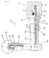
- FIG. 5 to 10 is a hidden one Screw connection for pipes shown, with pipe 44 with for example a wall 18 is connected.
- the pressing part 50 is by the screw 48 by means of the rivet nut 46 in the Screwed tube 44.
- the pipe act as a front door pull handle or the like.
- the head of the screw 48 lies against an inner shoulder or a step of the pressing part 50.
- the screw 48 required large internal dimensions of the central Bore through the pressing part 50 reduced.
- screwing in the screw 36 for example one Grub screw, will guide and mount the sleeve part 42 reached.
- the screw 36 and the Screw 48 also by a grub screw or the like can be replaced, in which case the pressing part 50 by means of a nut screwed onto the grub screw that holds the Function of the head of the screw 48 replaced with the tube 44 can be braced. Then the sleeve part 42 to screwed onto the screw 36 until it stops in the contact part 50, the rosette 34 plugged in and again through the sleeve part Right turn on the previously in the wall 18 or door or similarly fastened dowels 32 with grub screw 38 screwed. Even with this type of attachment optimal, invisible screw connection achieved because the sleeve 28th of the sleeve part 42, the pressing part 50 before and after Completion of the screw connection covered.
- the sleeve part 42 preferably has an im in all embodiments essential circular cylindrical outer wall on and closes the view inside the screw connection, whereby also the actual function of the sleeve part 42 as Connection or screwing element to the outside is not is recognizable.
- the shown in Figures 6 to 10 Sectional representations of the individual components of Figure 5 serve a better explanation of the components used.
- FIG. 11 Another embodiment of a covert
- the screw connection for handrail brackets is shown in Figure 11 shown, with here, for example, a wooden handrail 54 various components with, for example, a wall 18 connected is.
- the assembly proceeds as follows: An anchor 56 is inserted into a hole in the wooden handrail 54 used and a screw 58, for example one Set screw, a grub screw or the like in the dowel 56 turned. Then the pressing part 60 on the Screw 58 attached and the pin part 62 of the screw 58 turned up until a front shoulder of the pin part against one Presses ring wall of the pressing part 60 and the pressing part 60 with braced the wooden handrail 54.
- the pin part 62 has one rear, rod-like approach on that in a hole of the guide part 64 is inserted.
- an inner Threaded bore of the guide part 64 is, for example Screw 6b, such as grub screw or the like, with the pin part 62 on the guide part 64 by screwing it in can be clamped.
- FIG Device for concealed handle bar holder reproduced.
- a handle bar 68 in turn for example on a wall 18, a door or the like fixed.
- the rivet nut 76 is in the handle bar 68 attached and then the pressure member 74 by means of the screw 32nd fixed to the handle bar 68. Then that will Contact part in a blind hole in the guide part pushed, the pressing member 74 by means of a transverse to Blind hole and a threaded hole screwed screw 36 jamming in the blind hole is set.
- This screw 36 will again Screwed sleeve part 42 up to the stop and then through Turn clockwise on the screw 38, which by means of the plug 32 in the wall 18 or the like is fixed.
- the embodiment of Figure 13 shows a continuously adjustable wall bracket to fix a tube 78 or a post, for example on a stair string 84.
- Reference number 86 schematically indicates a step.
- the tube becomes essentially identical by means of two trained fasteners on the stair string 84 fixed.
- the dowels 32 are inserted into the stair string 84 inserted and the setscrew 80 screwed into the dowel 32.
- the rosette 34 is then placed on the threaded pin 80 and the sleeve part 42 is unscrewed.
- the Threaded sleeve 82 also up to the stop on the Set screw 80 turned on, the sleeve 28 of the sleeve part 40 engages over the threaded nut 82.
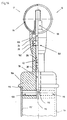
- a Pipe plug with concealed screw connection for the Handrail bracket shown.
- a rivet nut is used 98 riveted into the tube 94 for the handrail and the Screw 100 screwed in.
- the pressing part 104 slipped onto the screw 100 and by means of the nut 102 clamped with the tube 94.
- On the free end section of the Screw 100 becomes the sleeve part 42 with its internal thread screwed in as far as it will go.
- the sleeve 28 overlaps the Pressing part 104, the sleeve part 42.
- the Screw 38 into the central bore of the end plug 106 screwed in so that the transverse to this hole in the End plug 106 radially displaceable clamping pins 108, 110 are pressed radially outward and the inner wall 112 of the tube 96 by clamping.
- the screw 38 at its end facing the clamping pins 108, 110 as well like the clamping pins 108, 110 itself, a truncated cone shape 116 on.
- the end of the tube 96 is the sleeve part 42 by turning to the right on the end protruding from the end plug 106 Screw 38 unscrewed, the sleeve part 42 partially in axial direction from the sleeve 28 of the pressing part 104 is pushed out.
- the embodiment of Figure 15 shows a covert Glass holder screw connection, for example for as Glass panes serving as banisters 118.
- a rivet nut 120 is attached, then the Contact 124 which is screwed into the rivet nut 122 Screw 126 attached.
- the pin part 128 On the free end of this screw 126, which is arranged within the bore of the pressing part 124 is the pin part 128 with its internal thread turned up.
- the guide part 132 is attached with its bore and clamped on the pin part 128 by means of the screw 130 fixed.
- the guide member 132 is Tolerance compensation laterally adjustable on the pin part 128.
- the cap 134 has a threaded blind hole and lies below the glass pane 118, if necessary Interposition of spring elements.
- FIG 16 shows an embodiment of a covert System screwing of a railing with a handrail.
- a tube 136 which serves as a handrail, with a pipe 158, for example a post or the like, connected by means of a concealed screw connection.
- the pressing part 142 by means of the rivet nut 138 and screw 140 and the threaded insert 144, which on the free end of the Screw 140 is screwed on.
- the filler rods 150 are by means of Guide parts 148 and the screws 156 clamped, then through the free ends of the screws 156 corresponding holes in the pipe 158 inserted and be fixed to the pipe by means of the caps 152.
- Connecting devices for railings and the like not have visible screw connection and the advantage have that in conventional connecting devices required welding, grinding and polishing work in Connection area can be omitted. Furthermore, they are Connection device kept in a modern design and visually appealing for the user.
Landscapes
- Engineering & Computer Science (AREA)
- Architecture (AREA)
- Civil Engineering (AREA)
- Structural Engineering (AREA)
- Steps, Ramps, And Handrails (AREA)
- Mutual Connection Of Rods And Tubes (AREA)
- Bridges Or Land Bridges (AREA)
Abstract
Description
- Figur 1
- ein Ausführungsbeispiel einer verdeckten Verschraubung für Zierstäbe, teilweise geschnitten,
- Figur 2
- das Führungsteil der Figur 1, geschnitten,
- Figur 3
- das Hülsenteil der Figur 1, geschnitten,
- Figur 4
- die Rosette der Figur 1, geschnitten,
- Figur 5
- ein Ausführungsbeispiel einer verdeckten Verschraubung für Rohre, teilweise geschnitten,
- Figur 6
- die Einnietmutter der Figur 5, geschnitten,
- Figur 7
- das Anpreßteil der Figur 5, teilweise geschnitten,
- Figur 8
- den Gewindeeinsatz der Figur 5, geschnitten,
- Figur 9
- das Hülsenteil der Figur 5, geschnitten,
- Figur 10
- die Rosette der Figur 5, geschnitten,
- Figur 11
- ein Ausführungsbeispiel einer verdeckten Verschraubung für Handlaufhalterungen, teilweise geschnitten,
- Figur 12
- ein Ausführungsbeispiel einer verdeckten Griffstangenhalterung, teilweise geschnitten,
- Figur 13
- ein Ausführungsbeispiel eines stufenlos verstellbaren Wandhalters mit verdeckter Verschraubung, teilweise geschnitten,
- Figur 14
- ein Ausführungsbeispiel eines Rohrabschlußstopfens mit verdeckter Verschraubung für Handlaufhalterung, teilweise geschnitten,
- Figur 15
- ein Ausführungsbeispiel einer verdeckten Glashalterverschraubung, teilweise geschnitten und
- Figur 16
- ein Ausführungsbeispiel einer verdeckten Systemverschraubung Geländer-Handlauf, teilweise geschnitten.
- 10
- - Vorrichtung
- 12
- - 1. Gegenstand
- 14
- - 2. Gegenstand
- 16
- - Zierstab
- 18
- - Wand
- 22
- - Ringnut
- 24
- - Gewindemittel
- 26
- - Gewindemittel
- 28
- - Hülse
- 30
- - Gewindemittel
- 32
- - Dübel
- 34
- - Rosette
- 36
- - Schraube
- 38
- - Schraube
- 40
- - Führungsteil
- 42
- - Hülsenteil
- 44
- - Rohr
- 46
- - Einnietmutter
- 48
- - Schraube
- 50
- - Anpreßteil
- 52
- - Gewindeeinsatz
- 54
- - Holzhandlauf
- 56
- - Dübel
- 58
- - Schraube
- 60
- - Anpreßteil
- 62
- - Stiftteil
- 64
- - Führungsteil
- 66
- - Schraube
- 68
- - Griffstange
- 70
- - Führungsteil
- 72
- - Schraube
- 74
- - Anpreßteil
- 76
- - Einnietmutter
- 78
- - Rohr
- 80
- - Gewindestift
- 82
- - Gewindemutter
- 84
- - Treppenwange
- 86
- - Stufe
- 88
- - Rohrendstück
- 90
- - Distanzstück
- 94
- - Rohr
- 96
- - Rohr
- 98
- - Einnietmutter
- 100
- - Schraube
- 102
- - Mutter
- 104
- - Anpreßteil
- 106
- - Abschlußstopfen
- 108
- - Klemmstift
- 110
- - Klemmstift
- 112
- - Innenwandung
- 114
- - Ringwand
- 116
- - Kegelstumpfform
- 118
- - Glasscheibe
- 120
- - Pfosten
- 122
- - Einnietmutter
- 124
- - Anpreßteil
- 126
- - Schraube
- 128
- - Stiftteil
- 130
- - Schraube
- 132
- - Führungsteil
- 134
- - Kappe
- 136
- - Rohr
- 138
- - Einnietmutter
- 140
- - Schraube
- 142
- - Anpreßteil
- 144
- - Gewindeeinsatz
- 146
- - Führungsteil
- 148
- - Führungsteil
- 150
- - Füllstab
- 152
- - Kappe
- 154
- - Schraube
- 156
- - Schraube
- 158
- - Rohr
Claims (4)
- Vorrichtung (10) zum Verbindung von Gegenständen im Tür-, Möbel-, Glas- oder Geländerbau, wie Zierstäbe, Rohre, Handläufe, Griffstangen, Glasscheiben, Halterungen für diese Gegenstände, wie Anpreßteile, Stiftteile, Gewindeeinsätze, Führungsteile, Hülsen oder dergleichen, miteinander oder mit anderen Gegenständen, wie Wand, Hauswand, Treppenstufe, -wange oder dergleichen, wobei die Vorrichtung (10) wenigstens ein erstes und ein zweites, über korrespondierende Gewindemittel (24, 26) miteinander in Eingriff stehende Bauteile aufweist, die durch relatives verdrehen axial zueinander verstellbar sind, und das eine Bauteil das andere Bauteil zumindest über einen axialen Teilbereich nach Art einer Hülse (28), topfförmigen Aufnahme oder dergleichen übergreift, dadurch gekennzeichnet, daß das erste Bauteil ein Abschlußstopfen (106) für ein Rohr (96) mit einer im wesentlichen axialen Gewindebohrung und das zweite Bauteil eine Schraube (38), wie Gewindestange, - stift, Madenschraube oder dergleichen ist, die beim Einschrauben in die Gewindebohrung wenigstens ein, bevorzugt zwei oder mehrere, quer zur Gewindebohrung in Aufnahmen verschiebbar gelagerte Klemmstifte (108, 110) radial nach außen zur klemmenden Festlegung des Abschlußstopfens (106) an der Innenwandung (112) des Rohres (96) verschiebt.
- Vorrichtung nach Anspruch 1, dadurch gekennzeichnet, daß der Abschlußstopfen (106) eine äußere umlaufende Ringwand (114) besitzt, die die Wand des Rohres (96) übergreift.
- Vorrichtung nach einem der vorhergehenden Ansprüche, dadurch gekennzeichnet, daß die einander anliegenden Endabschnitte von Klemmstift (108, 110) und Schraube (38) eine korrespondierende Kegelstumpfform (116) aufweisen, wobei die Schrägflächen bevorzugt um ca. 45 geneigt sind
- Vorrichtung nach einem der vorhergehenden Ansprüche, dadurch gekennzeichnet, daß das als Schraube (38) ausgebildete zweite Bauteil zur Verschraubung mit einem weiteren Bauteil dient.
Applications Claiming Priority (8)
| Application Number | Priority Date | Filing Date | Title |
|---|---|---|---|
| DE29915362U | 1999-09-01 | ||
| DE29915361 | 1999-09-01 | ||
| DE29915361U | 1999-09-01 | ||
| DE29915362 | 1999-09-01 | ||
| DE29920366 | 1999-11-19 | ||
| DE29920366U | 1999-11-19 | ||
| DE20006273U DE20006273U1 (de) | 1999-09-01 | 2000-04-05 | Vorrichtung zum Verbinden von Gegenständen im Tür-, Möbel-, Glas- oder Geländerbau |
| DE20006273U | 2000-04-05 |
Publications (3)
| Publication Number | Publication Date |
|---|---|
| EP1081308A2 true EP1081308A2 (de) | 2001-03-07 |
| EP1081308A3 EP1081308A3 (de) | 2002-03-13 |
| EP1081308B1 EP1081308B1 (de) | 2006-10-11 |
Family
ID=27439020
Family Applications (1)
| Application Number | Title | Priority Date | Filing Date |
|---|---|---|---|
| EP00118576A Expired - Lifetime EP1081308B1 (de) | 1999-09-01 | 2000-08-26 | Vorrichtung zum Verbinden von Gegenständen im Geländerbau |
Country Status (3)
| Country | Link |
|---|---|
| EP (1) | EP1081308B1 (de) |
| AT (1) | ATE342413T1 (de) |
| DE (1) | DE50013596D1 (de) |
Cited By (1)
| Publication number | Priority date | Publication date | Assignee | Title |
|---|---|---|---|---|
| CN113208487A (zh) * | 2021-05-08 | 2021-08-06 | 温州市人民医院 | 浴室安全装置 |
Family Cites Families (3)
| Publication number | Priority date | Publication date | Assignee | Title |
|---|---|---|---|---|
| US3561798A (en) * | 1969-10-13 | 1971-02-09 | Allis Chalmers Mfg Co | Disconnect switch having internally clamped rotary coupling |
| AT352546B (de) * | 1977-10-06 | 1979-09-25 | Pletscher Fa Geb | Einrichtung zum loesbaren, kraftschluessigen verspannen zweier ineinander geschobener rohre, insbesondere zum verspannen des lenker- achsrohres im lenkgabelrohr eines fahrrades |
| DE3342668A1 (de) * | 1983-11-25 | 1985-06-05 | Neucon Maschinen- Und Bausysteme Gmbh U. Co Kg, 7100 Heilbronn | Gelaenderstab |
-
2000
- 2000-08-26 AT AT00118576T patent/ATE342413T1/de not_active IP Right Cessation
- 2000-08-26 DE DE50013596T patent/DE50013596D1/de not_active Expired - Lifetime
- 2000-08-26 EP EP00118576A patent/EP1081308B1/de not_active Expired - Lifetime
Cited By (1)
| Publication number | Priority date | Publication date | Assignee | Title |
|---|---|---|---|---|
| CN113208487A (zh) * | 2021-05-08 | 2021-08-06 | 温州市人民医院 | 浴室安全装置 |
Also Published As
| Publication number | Publication date |
|---|---|
| EP1081308B1 (de) | 2006-10-11 |
| EP1081308A3 (de) | 2002-03-13 |
| DE50013596D1 (de) | 2006-11-23 |
| ATE342413T1 (de) | 2006-11-15 |
Similar Documents
| Publication | Publication Date | Title |
|---|---|---|
| EP0469107B1 (de) | Verbindungselement für eine stange | |
| DE4030978C2 (de) | Verbindungseinrichtung für Rohre | |
| DE9102252U1 (de) | Verbindungssystem für zwei als Rohr- oder Stangen- und/oder Knotenelemente ausgebildete Bauteile | |
| EP1588975B1 (de) | Abhängeelement | |
| DE29500655U1 (de) | Bausatz aus verschiedenen Rundstäben zum Aufbau eines verkröpften Rundstab-Zugs | |
| DE8903833U1 (de) | Distanzschraube | |
| EP1081309A2 (de) | Vorrichtung zum Verbinden von Gegenständen im Tür-, Möbel-, Glas- und Geländerbau | |
| EP1081308A2 (de) | Vorrichtung zum Verbinden von Gegenständen im Tür-, Möbel-, Glas- und Geländerbau | |
| DE20006273U1 (de) | Vorrichtung zum Verbinden von Gegenständen im Tür-, Möbel-, Glas- oder Geländerbau | |
| EP1088949A2 (de) | Vorrichtung zum Verbinden von Gegenständen im Tür-, Möbel-, Glas- und Geländerbau | |
| DE19619390C1 (de) | Geländersystem, insbesondere für Treppen | |
| DE4009371C2 (de) | ||
| DE2011035A1 (de) | Verbindungselement, insbesondere für Möbelteile | |
| DE3401426C2 (de) | Bauelementsatz mit einer Befestigungsvorrichtung | |
| DE19808628A1 (de) | Vorrichtung zur Befestigung von Muttern in der Art einer Annietmutter | |
| DE102005051103B4 (de) | Vorrichtung zum Verbinden von Gegenständen im Tür-, Möbel-, Glas- oder Geländerbau | |
| DE4406900C2 (de) | Verbindungsvorrichtung, insbesondere zum Verbinden von zwei Anschlußenden aufweisenden Knoten-, Bogen- oder Rohrelementen eines Montagesystems | |
| DE29821143U1 (de) | Abzieher mit schnellverstellbarer Druckspindel | |
| EP0579070B1 (de) | Verbindungselement für Rohre | |
| WO1992016700A1 (de) | Verbindungselement für raumfachwerk | |
| DE4444279C2 (de) | Geländer für Treppen, Brüstungen oder dergleichen | |
| DE20003568U1 (de) | Sackloch Schaftschraube für Möbel, Bauteile, Drehverbindungen mit einstellbarer Drehbremse | |
| DE10135364C1 (de) | Aufsteckelement, insbesondere für ein Treppengeländer mit Metallstäben | |
| EP3842600A1 (de) | Befestigungssystem für handlauf | |
| DE202004019403U1 (de) | Gelenkverbinder |
Legal Events
| Date | Code | Title | Description |
|---|---|---|---|
| PUAI | Public reference made under article 153(3) epc to a published international application that has entered the european phase |
Free format text: ORIGINAL CODE: 0009012 |
|
| AK | Designated contracting states |
Kind code of ref document: A2 Designated state(s): AT BE CH CY DE DK ES FI FR GB GR IE IT LI LU MC NL PT SE |
|
| AX | Request for extension of the european patent |
Free format text: AL;LT;LV;MK;RO;SI |
|
| PUAL | Search report despatched |
Free format text: ORIGINAL CODE: 0009013 |
|
| AK | Designated contracting states |
Kind code of ref document: A3 Designated state(s): AT BE CH CY DE DK ES FI FR GB GR IE IT LI LU MC NL PT SE |
|
| AX | Request for extension of the european patent |
Free format text: AL;LT;LV;MK;RO;SI |
|
| 17P | Request for examination filed |
Effective date: 20020826 |
|
| AKX | Designation fees paid |
Free format text: AT BE CH CY DE DK ES FI FR GB GR IE IT LI LU MC NL PT SE |
|
| 17Q | First examination report despatched |
Effective date: 20040621 |
|
| GRAP | Despatch of communication of intention to grant a patent |
Free format text: ORIGINAL CODE: EPIDOSNIGR1 |
|
| RTI1 | Title (correction) |
Free format text: DEVICE FOR CONNECTING ARTICLES IN HANDRAIL CONSTRUCTIONS |
|
| GRAS | Grant fee paid |
Free format text: ORIGINAL CODE: EPIDOSNIGR3 |
|
| GRAA | (expected) grant |
Free format text: ORIGINAL CODE: 0009210 |
|
| AK | Designated contracting states |
Kind code of ref document: B1 Designated state(s): AT BE CH CY DE DK ES FI FR GB GR IE IT LI LU MC NL PT SE |
|
| PG25 | Lapsed in a contracting state [announced via postgrant information from national office to epo] |
Ref country code: IE Free format text: LAPSE BECAUSE OF FAILURE TO SUBMIT A TRANSLATION OF THE DESCRIPTION OR TO PAY THE FEE WITHIN THE PRESCRIBED TIME-LIMIT Effective date: 20061011 Ref country code: NL Free format text: LAPSE BECAUSE OF FAILURE TO SUBMIT A TRANSLATION OF THE DESCRIPTION OR TO PAY THE FEE WITHIN THE PRESCRIBED TIME-LIMIT Effective date: 20061011 Ref country code: FI Free format text: LAPSE BECAUSE OF FAILURE TO SUBMIT A TRANSLATION OF THE DESCRIPTION OR TO PAY THE FEE WITHIN THE PRESCRIBED TIME-LIMIT Effective date: 20061011 Ref country code: IT Free format text: LAPSE BECAUSE OF FAILURE TO SUBMIT A TRANSLATION OF THE DESCRIPTION OR TO PAY THE FEE WITHIN THE PRE;WARNING: LAPSES OF ITALIAN PATENTS WITH EFFECTIVE DATE BEFORE 2007 MAY HAVE OCCURRED AT ANY TIME BEFORE 2007. THE CORRECT EFFECTIVE DATE MAY BE DIFFERENT FROM THE ONE RECORDED.SCRIBED TIME-LIMIT Effective date: 20061011 |
|
| REG | Reference to a national code |
Ref country code: GB Ref legal event code: FG4D Free format text: NOT ENGLISH |
|
| REG | Reference to a national code |
Ref country code: CH Ref legal event code: EP |
|
| REG | Reference to a national code |
Ref country code: IE Ref legal event code: FG4D Free format text: LANGUAGE OF EP DOCUMENT: GERMAN |
|
| REF | Corresponds to: |
Ref document number: 50013596 Country of ref document: DE Date of ref document: 20061123 Kind code of ref document: P |
|
| PG25 | Lapsed in a contracting state [announced via postgrant information from national office to epo] |
Ref country code: SE Free format text: LAPSE BECAUSE OF FAILURE TO SUBMIT A TRANSLATION OF THE DESCRIPTION OR TO PAY THE FEE WITHIN THE PRESCRIBED TIME-LIMIT Effective date: 20070111 Ref country code: DK Free format text: LAPSE BECAUSE OF FAILURE TO SUBMIT A TRANSLATION OF THE DESCRIPTION OR TO PAY THE FEE WITHIN THE PRESCRIBED TIME-LIMIT Effective date: 20070111 |
|
| PG25 | Lapsed in a contracting state [announced via postgrant information from national office to epo] |
Ref country code: ES Free format text: LAPSE BECAUSE OF FAILURE TO SUBMIT A TRANSLATION OF THE DESCRIPTION OR TO PAY THE FEE WITHIN THE PRESCRIBED TIME-LIMIT Effective date: 20070122 |
|
| PG25 | Lapsed in a contracting state [announced via postgrant information from national office to epo] |
Ref country code: PT Free format text: LAPSE BECAUSE OF FAILURE TO SUBMIT A TRANSLATION OF THE DESCRIPTION OR TO PAY THE FEE WITHIN THE PRESCRIBED TIME-LIMIT Effective date: 20070319 |
|
| NLV1 | Nl: lapsed or annulled due to failure to fulfill the requirements of art. 29p and 29m of the patents act | ||
| GBV | Gb: ep patent (uk) treated as always having been void in accordance with gb section 77(7)/1977 [no translation filed] |
Effective date: 20061011 |
|
| EN | Fr: translation not filed | ||
| REG | Reference to a national code |
Ref country code: IE Ref legal event code: FD4D |
|
| PLBE | No opposition filed within time limit |
Free format text: ORIGINAL CODE: 0009261 |
|
| STAA | Information on the status of an ep patent application or granted ep patent |
Free format text: STATUS: NO OPPOSITION FILED WITHIN TIME LIMIT |
|
| 26N | No opposition filed |
Effective date: 20070712 |
|
| PG25 | Lapsed in a contracting state [announced via postgrant information from national office to epo] |
Ref country code: GB Free format text: LAPSE BECAUSE OF FAILURE TO SUBMIT A TRANSLATION OF THE DESCRIPTION OR TO PAY THE FEE WITHIN THE PRESCRIBED TIME-LIMIT Effective date: 20061011 |
|
| BERE | Be: lapsed |
Owner name: JUNG, WILLI Effective date: 20070831 |
|
| REG | Reference to a national code |
Ref country code: CH Ref legal event code: PL |
|
| PG25 | Lapsed in a contracting state [announced via postgrant information from national office to epo] |
Ref country code: MC Free format text: LAPSE BECAUSE OF NON-PAYMENT OF DUE FEES Effective date: 20070831 Ref country code: LI Free format text: LAPSE BECAUSE OF NON-PAYMENT OF DUE FEES Effective date: 20070831 Ref country code: GR Free format text: LAPSE BECAUSE OF FAILURE TO SUBMIT A TRANSLATION OF THE DESCRIPTION OR TO PAY THE FEE WITHIN THE PRESCRIBED TIME-LIMIT Effective date: 20070112 Ref country code: CH Free format text: LAPSE BECAUSE OF NON-PAYMENT OF DUE FEES Effective date: 20070831 Ref country code: FR Free format text: LAPSE BECAUSE OF FAILURE TO SUBMIT A TRANSLATION OF THE DESCRIPTION OR TO PAY THE FEE WITHIN THE PRESCRIBED TIME-LIMIT Effective date: 20070601 |
|
| PG25 | Lapsed in a contracting state [announced via postgrant information from national office to epo] |
Ref country code: BE Free format text: LAPSE BECAUSE OF NON-PAYMENT OF DUE FEES Effective date: 20070831 |
|
| PG25 | Lapsed in a contracting state [announced via postgrant information from national office to epo] |
Ref country code: FR Free format text: LAPSE BECAUSE OF FAILURE TO SUBMIT A TRANSLATION OF THE DESCRIPTION OR TO PAY THE FEE WITHIN THE PRESCRIBED TIME-LIMIT Effective date: 20061011 Ref country code: AT Free format text: LAPSE BECAUSE OF NON-PAYMENT OF DUE FEES Effective date: 20070826 |
|
| PG25 | Lapsed in a contracting state [announced via postgrant information from national office to epo] |
Ref country code: CY Free format text: LAPSE BECAUSE OF FAILURE TO SUBMIT A TRANSLATION OF THE DESCRIPTION OR TO PAY THE FEE WITHIN THE PRESCRIBED TIME-LIMIT Effective date: 20061011 Ref country code: LU Free format text: LAPSE BECAUSE OF NON-PAYMENT OF DUE FEES Effective date: 20070826 |
|
| PGFP | Annual fee paid to national office [announced via postgrant information from national office to epo] |
Ref country code: DE Payment date: 20150831 Year of fee payment: 16 |
|
| REG | Reference to a national code |
Ref country code: DE Ref legal event code: R119 Ref document number: 50013596 Country of ref document: DE |
|
| PG25 | Lapsed in a contracting state [announced via postgrant information from national office to epo] |
Ref country code: DE Free format text: LAPSE BECAUSE OF NON-PAYMENT OF DUE FEES Effective date: 20170301 |