EP1081443B1 - Verfahren und Herstellung eines Lüftungskanals - Google Patents
Verfahren und Herstellung eines Lüftungskanals Download PDFInfo
- Publication number
- EP1081443B1 EP1081443B1 EP00850147A EP00850147A EP1081443B1 EP 1081443 B1 EP1081443 B1 EP 1081443B1 EP 00850147 A EP00850147 A EP 00850147A EP 00850147 A EP00850147 A EP 00850147A EP 1081443 B1 EP1081443 B1 EP 1081443B1
- Authority
- EP
- European Patent Office
- Prior art keywords
- protective sheet
- duct
- ventilation duct
- construction
- insulated
- Prior art date
- Legal status (The legal status is an assumption and is not a legal conclusion. Google has not performed a legal analysis and makes no representation as to the accuracy of the status listed.)
- Expired - Lifetime
Links
- 238000009423 ventilation Methods 0.000 title claims abstract description 65
- 238000010276 construction Methods 0.000 title claims abstract description 42
- 238000000034 method Methods 0.000 title claims abstract description 10
- 230000001681 protective effect Effects 0.000 claims abstract description 84
- 239000002184 metal Substances 0.000 claims abstract description 14
- 239000003063 flame retardant Substances 0.000 claims abstract description 12
- 239000003570 air Substances 0.000 claims description 38
- 238000009413 insulation Methods 0.000 claims description 28
- 125000006850 spacer group Chemical group 0.000 claims description 8
- 239000012080 ambient air Substances 0.000 claims description 4
- 239000002344 surface layer Substances 0.000 claims 2
- 239000006096 absorbing agent Substances 0.000 abstract description 55
- 230000002035 prolonged effect Effects 0.000 abstract description 3
- 230000000694 effects Effects 0.000 description 7
- 238000001816 cooling Methods 0.000 description 6
- 229910000831 Steel Inorganic materials 0.000 description 3
- 239000011810 insulating material Substances 0.000 description 3
- 239000011490 mineral wool Substances 0.000 description 3
- 239000010959 steel Substances 0.000 description 3
- 239000011358 absorbing material Substances 0.000 description 2
- 230000008901 benefit Effects 0.000 description 2
- 238000010586 diagram Methods 0.000 description 2
- 239000011491 glass wool Substances 0.000 description 2
- 238000010438 heat treatment Methods 0.000 description 2
- 239000000463 material Substances 0.000 description 2
- 238000005259 measurement Methods 0.000 description 2
- 230000000153 supplemental effect Effects 0.000 description 2
- 230000005494 condensation Effects 0.000 description 1
- 238000009833 condensation Methods 0.000 description 1
- 238000009434 installation Methods 0.000 description 1
- 229920000728 polyester Polymers 0.000 description 1
- 230000001902 propagating effect Effects 0.000 description 1
- 230000000284 resting effect Effects 0.000 description 1
- 239000000725 suspension Substances 0.000 description 1
Images


Classifications
-
- F—MECHANICAL ENGINEERING; LIGHTING; HEATING; WEAPONS; BLASTING
- F24—HEATING; RANGES; VENTILATING
- F24F—AIR-CONDITIONING; AIR-HUMIDIFICATION; VENTILATION; USE OF AIR CURRENTS FOR SCREENING
- F24F13/00—Details common to, or for air-conditioning, air-humidification, ventilation or use of air currents for screening
- F24F13/02—Ducting arrangements
- F24F13/0263—Insulation for air ducts
-
- F—MECHANICAL ENGINEERING; LIGHTING; HEATING; WEAPONS; BLASTING
- F16—ENGINEERING ELEMENTS AND UNITS; GENERAL MEASURES FOR PRODUCING AND MAINTAINING EFFECTIVE FUNCTIONING OF MACHINES OR INSTALLATIONS; THERMAL INSULATION IN GENERAL
- F16L—PIPES; JOINTS OR FITTINGS FOR PIPES; SUPPORTS FOR PIPES, CABLES OR PROTECTIVE TUBING; MEANS FOR THERMAL INSULATION IN GENERAL
- F16L59/00—Thermal insulation in general
- F16L59/14—Arrangements for the insulation of pipes or pipe systems
- F16L59/143—Pre-insulated pipes
-
- F—MECHANICAL ENGINEERING; LIGHTING; HEATING; WEAPONS; BLASTING
- F16—ENGINEERING ELEMENTS AND UNITS; GENERAL MEASURES FOR PRODUCING AND MAINTAINING EFFECTIVE FUNCTIONING OF MACHINES OR INSTALLATIONS; THERMAL INSULATION IN GENERAL
- F16L—PIPES; JOINTS OR FITTINGS FOR PIPES; SUPPORTS FOR PIPES, CABLES OR PROTECTIVE TUBING; MEANS FOR THERMAL INSULATION IN GENERAL
- F16L59/00—Thermal insulation in general
- F16L59/14—Arrangements for the insulation of pipes or pipe systems
- F16L59/145—Arrangements for the insulation of pipes or pipe systems providing fire-resistance
-
- F—MECHANICAL ENGINEERING; LIGHTING; HEATING; WEAPONS; BLASTING
- F24—HEATING; RANGES; VENTILATING
- F24F—AIR-CONDITIONING; AIR-HUMIDIFICATION; VENTILATION; USE OF AIR CURRENTS FOR SCREENING
- F24F13/00—Details common to, or for air-conditioning, air-humidification, ventilation or use of air currents for screening
- F24F13/02—Ducting arrangements
- F24F13/0281—Multilayer duct
-
- F—MECHANICAL ENGINEERING; LIGHTING; HEATING; WEAPONS; BLASTING
- F24—HEATING; RANGES; VENTILATING
- F24F—AIR-CONDITIONING; AIR-HUMIDIFICATION; VENTILATION; USE OF AIR CURRENTS FOR SCREENING
- F24F2221/00—Details or features not otherwise provided for
- F24F2221/30—Details or features not otherwise provided for comprising fireproof material
Definitions
- the present invention relates to a ventilation duct construction, comprising a ventilation duct which is provided with insulation and through which air is allowed to flow, as well as a method for increasing the fire-retardant capability of a ventilation duct provided with insulation.
- Fire-retardant capability is here defined as the capability to resist such a temperature rise of the duct air as causes a temperature rise on the outside of the construction.
- insulating material such as rock wool
- insulation is arranged on the outside of the wall of the duct and is in most cases provided with an outer metal cover.
- the ventilation ducts serve to convey air, but noise also propagates easily.
- sound-absorbing material such as rock wool or glass wool
- materials which are less fire-retardant e.g. polyester insulation
- Prior art WO93/11327A discloses one way of providing fire-retardant capability to ducts in the form of an insulated ventilation duct component and method of producing the same.
- the duct component comprises an external metal sheet casing and an internal metal sheet casing.
- An insulating material layer is arranged in the space between the external and internal casings.
- the external and internal casings are interconnected by one or more perforated metal sheet elements which cover the corresponding end surfaces of the insulating material layer. The perforations reduce the amount of heat that might be conducted between the internal and external casings.
- one object of the present invention is to provide an insulated ventilation duct construction, in which the time during which the outside temperature can be kept down in case of fire is prolonged, while the construction remains compact.
- the invention is thus based on the understanding that the fire-retardant capability can be increased by arranging, at least partially, a supplemental thin boundary layer outwardly of the insulated duct or the sound absorber, which boundary layer, on the one hand, provides a supplemental cover configuration having what might be considered as a heat-exchange function and, on the other, provides an additional air insulation effect.
- a protective sheet made of metal is thus arranged at least partially around and close to the duct and its associated insulation, not in direct contact with the insulated duct, but instead at a short distance from the same so that an air gap is formed therebetween.
- the thermal bridge between the protective sheet and the duct and its associated insulation is made very small, which can easily be achieved with the aid of suitably designed spacer means.
- the time of heating the protective sheet is prolonged and in particular the time of heating its outside, i.e. the outside of the entire construction.
- the protective sheet at least initially, has a cooling effect on the hot air in the gap which has been heated by fire.
- the thicker the selected protective sheet the better the cooling capability.
- the selection of the width of the air gap as well as the thickness of the protective sheet must be adjusted to the demands on weight and space. It has been found that a satisfactory effect is obtained even when using a very thin protective sheet and a very small air gap.
- the protective sheet is made of metal, such as galvanised steel sheet.
- a typical protective sheet of galvanised steel sheet has a thickness of about one millimetre or a few millimetres, preferably about 1 mm.
- the size of the air gap i.e. the distance between the protective sheet and the insulated duct, is typically about one millimetre or a few millimetres, preferably about 1 mm.
- the protective sheet also has another effect, namely that of distributing the heat over the protective sheet in case it is locally exposed to a considerable temperature rise. This function is particularly pronounced if the protective sheet is made of a material having good thermal conductivity.
- the protective sheet can be provided with through-holes to improve the circulation of air and heat exchange. This is because cold ambient air is to be drawn into the gap through openings at the ends of the protective sheet, when the hot air leaks out of the gap through the holes of the protective sheet. As a result, a circulation of air is provided which contributes to the cooling of the air gap and the protective sheet.
- the number, shape and size of the holes can be selected depending on the desired qualities of the protective sheet. However, the size and the number of the holes have to be chosen, since too big or too many holes could counteract the purpose of the protective sheet. It has, however, been found that good effects are achieved also when the total area of the holes equals half the area of the protective sheet.
- the position of the protective sheet may vary. It is possible to surround an entire ventilation duct of about one hundred metres with a protective sheet in accordance with the invention, preferably in separate sections so as to provide openings for the intake of air. But it is also possible to provide a ventilation duct with protective sheet only locally along one or more specially selected sections, such as a sound absorber section. Irrespective of the above-mentioned alternatives, it is not necessary to arrange protective sheet along the entire circumference of the ventilation duct. It is quite possible that extra protection is needed only along a part of the circumference of the duct.
- the cross-sectional shape of the ventilation duct or the sound absorber may vary. Typical shapes are rectangular and circular, but other shapes are also feasible, since the invention is not limited to any particular shape of the duct.
- the shape of the protective sheet is suitably selected according to the shape of the ventilation duct or the sound absorber, and preferably in such manner that the shapes conform with each other.
- the manner in which the duct is insulated does not limit the scope of the invention. It is, for instance, possible to arrange, on the outside of the wall of the duct, a standard insulation, the outside of which is a metal cover adjacent to which the protective sheet is arranged with the air gap. A ventilation duct section with sound-absorbing insulation is also possible, the protective sheet being arranged so that an air gap forms between the same and the outer cover of the sound absorber. Other types of insulation are, of course, also feasible.
- the protective sheet can be kept at a suitable distance from the ventilation duct with the aid of spacer means so that said air gap forms.
- spacer means mention can be made of pins, screws, rivets and distance plates which are arranged between and fixed to the protective sheet and/or the wall of the ventilation duct or the insulation placed thereon, with or without a cover.
- the design of the spacer means should allow the thermal bridge to be minimised.
- the spacer means should be small and limited to a small number. It is also possible to form the air gap without any connection at all, and thus without a thermal bridge, between the protective sheet and the ventilation duct.
- One possibility is to equip the construction with magnets so that the protective sheet is kept “floating" about the ventilation duct. If there is enough space, another possibility of completely avoiding thermal bridges is to provide the protective sheet with an outer suspension which is connected to external holding elements.
- the present invention relates to a method for increasing the fire-retardant capability of an insulated ventilation duct. According to the method, this is achieved by placing a protective sheet made of metal externally at least partially around the insulated duct at such a distance from the same that an air gap forms between the protective sheet and the insulated duct.
- the invention is thus also applicable to existing installations, both to a conventional existing sound absorber and to other ventilation duct sections.
- the invention can also facilitate the mounting of a fire-protected sound absorber in a section of a ventilation duct. It is thus possible, for instance, to remove the fire insulation in the desired section, perforate the duct wall to "let out the sound", arrange sound insulation with an outer cover which forms the duct wall on the perforated duct wall and finally arrange the protective sheet according to the invention around the outer cover so that an air gap forms between the protective sheet and the outer cover.
- One common way of arranging a sound absorber in an existing ventilation duct is to cut off the duct and insert by splicing the sound absorber.
- a sound absorber equipped with a protective sheet according to the present invention can also be arranged in a ventilation duct in the same manner.
- the invention makes it possible to lower the requirements placed on the absorbing material of a sound absorber as concerns fire-retardancy for the benefit of improved absorbency, resulting in the possibility of reducing the dimensions in the transverse direction, while maintaining the same total fire-retardancy level.
- Fig. 1 schematically shows a longitudinal cross-section of a ventilation duct construction 1 according to an embodiment of the present invention.
- the Figure illustrates part of a ventilation duct 4 through which air is allowed to flow.
- the ventilation duct 4 is provided with a sound absorber section 6, which is fixed by means of annular flanges 7 projecting over and surrounding the wall 12 of the ventilation duct 4.
- the sound absorber 6 comprises an annular sound insulation 8 which is made of glass wool and which is open inwards to absorb noise propagating inside the ventilation duct 4.
- the sound insulation 8 is placed at an outer cover 10 of the sound absorber 6.
- a fire insulation 14 made of rock wool is arranged on the outside of the wall 12 of the ventilation duct 4, said fire insulation 14 being delimited outermost by a metal cover 16.
- the wall 12 of the ventilation duct 4 and its associated fire insulation 14 and metal cover are joined to the sound absorber 6 by means of the flanges 7, so that the wall 12 of the ventilation duct 4 merges into the duct-forming outer cover 10.
- a sleeve-shaped protective sheet 18 which has a thickness of about 0.7 mm and is made of galvanised steel sheet is arranged around the outer cover 10 of the sound absorber 6 in accordance with the invention.
- Rivets 20 which are arranged between the protective sheet 18 and the outer cover 10 keep the protective sheet 18 at a distance of about 1 mm from the outer cover 10 so that an air gap 22 forms therebetween. Openings 23 at the ends of the sheet allow cold ambient air to enter into the gap.
- the protective sheet is also perforated (which is shown in Fig. 3), and therefore a satisfactory air circulation with a cooling effect is obtained.
- the sound absorber 6 which is provided with the protective sheet 18 obtains considerably increased fire-retardancy compared with a sound absorber without a protective sheet. This will be discussed in more detail in connection with Fig. 6.
- Fig. 2 schematically shows a cross-section of the construction in Fig. 1 along the line II-II. It is apparent that in this embodiment the sound absorber is round in cross-section.
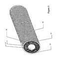
- Fig. 3 schematically shows a perspective view of the sound absorber in Figs 1 and 2, a perforated protective sheet 18 being illustrated, which provides a satisfactory air circulation, resulting in cooling of the protective sheet 18 and the air gap 22.
- Fig. 4 schematically shows a longitudinal cross-section of a ventilation duct construction 2 according to another embodiment of the present invention.
- the same reference numerals are used as in Fig. 1 for equivalent construction components.
- the wall 12 of the ventilation duct, adjacent to the sound absorber section merges into the wall 24 of a foraminated pipe, which is an integral part of the sound absorber.
- the foraminated pipe through which noise is emitted serves as a support for the sound insulation 8 resting thereon.
- the sound insulation 8 is, in usual manner, provided with an outer cover 10.
- the protective sheet 26 according to this embodiment is arranged not only around the sound absorber 6, but also around adjoining sections of the ventilation duct part.
- the protective sheet 26 is divided so that openings 28 allow the inflow of cooling air in a manner corresponding to that of the openings 23 in Fig. 1. A very good effect is, however, obtained for the protective sheet 26 also without the openings 28.
- Fig. 5 schematically shows a cross-section of the construction in Fig. 4 along the line V-V.
- the sound absorber in this embodiment is quadrangular in cross-section, which is to illustrate that the sound absorber is connected to a ventilation duct with quadrangular cross-section.
- Figs 1-5 are only shown for the purpose of exemplification and thus not according to scale.
- the sound absorber in Fig. 1 may, for instance, be provided with a foraminated pipe according to the construction in Fig. 4, just like the sound absorber in Fig. 4 can be designed in a different manner, without a foraminated pipe.
- the cross-sectional shapes are exchangeable, as is also the length of the protective sheet, and it is possible to select either a perforated or a non-perforated protective sheet.
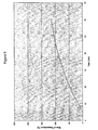
- Fig. 6 shows a diagram in which a comparison is made between a sound absorber with a protective sheet according to the present invention and a sound absorber without a protective sheet.
- Fire tests were performed by connecting a furnace to an inlet end of the respective sound absorbers, so that the air duct of the sound absorbers was connected with the furnace air.
- the temperature of the furnace was increased according to a standard fire curve (to about 600° C after 6 min and up to slightly more than 900° C after 60 min).
- Several thermoelements were placed on the outside of the respective constructions, i.e. on the outside of the protective sheet and the outside of the cover of the sound absorber, respectively. In the Figure, temperature values measured by a thermoelement, which was placed in the centre of the respective constructions, are compared.
- the dashed curve shows the temperature change on the outside of an ordinary sound absorber without any protective sheet.
- the unbroken curve shows the temperature change on the outside of an inventive protective sheet which is arranged on a sound absorber.
- a marked difference is obtained between the sound absorber with a protective sheet and the sound absorber without a protective sheet.
- the steep inclination at the beginning of the dashed curve is also worth noting. After only not quite ten minutes, the outside temperature of the conventional sound absorber increases dramatically, whereas when comparing with the sound absorber provided with a protective sheet an even and slowly increasing temperature can be noted.
Landscapes
- Engineering & Computer Science (AREA)
- General Engineering & Computer Science (AREA)
- Mechanical Engineering (AREA)
- Chemical & Material Sciences (AREA)
- Combustion & Propulsion (AREA)
- Duct Arrangements (AREA)
- Respiratory Apparatuses And Protective Means (AREA)
- Building Environments (AREA)
Claims (15)
- Belüftungskanalaufbau (1), umfassend einen Belüftungskanal (4), durch den Luft zu strömen zugelassen ist, wobei der Kanal durch isolationsmittel (8) in Verbindung mit der Wand (12) des Kanals isoliert ist,
dadurch gekennzeichnet, dass ein aus Metall gefertigtes Schutzblech (18, 26) äußerlich wenigstens teilweise um den Kanal (4) mit seiner zugehörigen Isolation (8) mit einem derartigen Abstand angeordnet ist, dass ein Luftspalt (22) zwischen dem Schutzblech (18, 26) und dem isolierten Kanal (4) gebildet ist, wodurch das feuerhemmende Vermögen, gemessen als das Vermögen, einem solchem Temperaturanstieg der Kanalluft zu widerstehen, der einen Temperaturanstieg an der Außenseite des Aufbaus, das heißt, an der Außenseite des Schulbuches (18, 26), verursacht, wesentlich erhöht ist, - Belüftungskanalaufbau (1) nach Anspruch 1, wobei an den jeweiligen Enden des Schutzbleches (18, 26) eine Öfnung (23) für Lufteinlass angeordnet ist, so dass Umgebungstuft ermöglicht wird, zwischen das Schutzblech und den isolierten Kanal (4) einzutreten.
- Belüftungskanalaufbau (1) nach Anspruch 1 oder 2, der wenigstens an einem Abschnitt der Kanalwand Schallisolierung im Innern einer Außenabdeckung (10), mit dem Ziel, Geräusche zu dämpfen und infolgedessen eine schalldämmende Funktion bereitzustellen, umfasst, wobei der Luftspalt (22) zwischen dem Schutzblech (18,26) und der Außenabdeckung gebildet ist.
- Belüftungskanalaufbau (1) nach Anspruch 3, wobei die Außenabdeckung (10) die Kanalwand (12) bildet.
- Belüttungskanalaufbau (1) nach Anspruch 3, wobei die Schallisolierung (8) von innen durch eine kleine Öffnungen aufweisende Stützkonstruktion, bevorzugt ein perforiertes Rohr, gehalten wird, wobei die Stützkonstruktion die Kanalwand bildet.
- Belüftungskanalaufbau (1) nach einem der vorhergehenden Ansprüche, der wenigstens an einem Abschnitt der Kanalwand (12) Feuerisolierung (8), die auf der Außenseite der Kanalwand (4) angeordnet ist, umfasst, wobei der Luftspalt (22) zwischen dem Schutzblech (18, 26) und der feuerisolierten Kanalwand (4) gebildet ist.
- Belüftuskanalaufbau (1) nach Anspruch 6, wobei die Feuerisolierung auf der Außenseite der Kanalwand (4) mit einer äußeren Oberflächenschicht, bevorzugt einer Metallabdeckung, versehen ist.
- Belüftungskanalaufbau (1) nach einem der vorhergehenden Ansprüche, wobei Distanzmittel (20) angeordnet sind, um den Luftspalt (22) zu dimensionieren.
- Belüftungskanalautbau (1) nach den Ansprüchen 7 und 8, wobei sich die Distanzmittel (20) zwischen dem Schutzblech und der Oberflächenschicht erstrecken.
- Belüftungskanalaufbau (1) nach einem der Ansprüche 3 bis 5 und nach Anspruch 8, wobei sich die Distanzmittel (20) zwischen dem Schutzblech (18, 26) und der Außenabdeckung erstrecken.
- Belüffungskanalaufbau (1) nach einem der vorhergehenden Anspruche" wobel der Abstand des Luftspaltes (22) ungefähr ein Millimeter oder einige Millimeter, bevorzugt ungefähr 1 mm, ist,
- Belüftungskanalaufbau (1) nach einem der vorhergehenden Ansprüche, wobei die Dicke des Schutzbleches (18, 26) ungefähr ein Millimeter oder einige Millimeter, bevorzugt ungefähr 1 mm, ist.
- Belüftungskanalaufbau (1) nach einem der vorhergehenden Ansprüche, Wobei das Schutzblech (18,26) mit Durchgangstöchern versehen ist.
- Verfahren zum Erhöhen des feuerhemmenden. Vemögens eines Belüftungskanals (4), der durch Isolationsmittel (8) in Verbindung mit der Wand (12) des Kanals isoliert ist,
gekennzeichnet durch das Platzieren eines aus Metall gefertigten Schutzbleches (18, 26) äußerlich wenigstens teilweise um den isolierten Kanal in einem solchem Abstand, dass sich zwischen dem Schutzblech und dem isolierten Kanal ein Luftspalt (22) bildet. - Verfahren nach Anspruch 14, das des Weiteren den Schritt des derafligen An. ordnens des Schutzbleches (18, 26) umfasst, dass Umgebungsluft ermöglich wird, an den jeweiligen Enden des Schutzbleches zwischen das Schutzblech und den isollerten Kanal (4) einzutreten,
Applications Claiming Priority (2)
| Application Number | Priority Date | Filing Date | Title |
|---|---|---|---|
| SE9903138 | 1999-09-06 | ||
| SE9903138A SE521502C2 (sv) | 1999-09-06 | 1999-09-06 | Ventilationskanalkonstruktion och förfarande därtill |
Publications (3)
| Publication Number | Publication Date |
|---|---|
| EP1081443A2 EP1081443A2 (de) | 2001-03-07 |
| EP1081443A3 EP1081443A3 (de) | 2003-09-10 |
| EP1081443B1 true EP1081443B1 (de) | 2006-06-07 |
Family
ID=20416865
Family Applications (1)
| Application Number | Title | Priority Date | Filing Date |
|---|---|---|---|
| EP00850147A Expired - Lifetime EP1081443B1 (de) | 1999-09-06 | 2000-09-05 | Verfahren und Herstellung eines Lüftungskanals |
Country Status (6)
| Country | Link |
|---|---|
| EP (1) | EP1081443B1 (de) |
| AT (1) | ATE329209T1 (de) |
| DE (1) | DE60028479D1 (de) |
| DK (1) | DK1081443T3 (de) |
| NO (1) | NO324432B1 (de) |
| SE (1) | SE521502C2 (de) |
Family Cites Families (6)
| Publication number | Priority date | Publication date | Assignee | Title |
|---|---|---|---|---|
| DE508731C (de) * | 1928-05-27 | 1930-10-01 | Rheinhlod & Co | Luftschicht-Isolierung mit Abstuetzungsgliedern |
| US2078606A (en) * | 1934-04-02 | 1937-04-27 | Grand Joseph M Le | Thermal insulation for valved pipe installation |
| US2613166A (en) * | 1949-03-11 | 1952-10-07 | George E Gronemeyer | Thermal insulation |
| US3902744A (en) * | 1974-04-01 | 1975-09-02 | Wallace Murray Corp | Prefabricated double-walled metal chimney |
| US3981689A (en) * | 1974-10-15 | 1976-09-21 | Hitco | Insulator |
| SE469480B (sv) * | 1991-11-28 | 1993-07-12 | Flaekt Ab | Isolerad ventilationskanalkomponent samt saett att tillverka densamma. |
-
1999
- 1999-09-06 SE SE9903138A patent/SE521502C2/sv not_active IP Right Cessation
-
2000
- 2000-09-05 NO NO20004436A patent/NO324432B1/no not_active IP Right Cessation
- 2000-09-05 DK DK00850147T patent/DK1081443T3/da active
- 2000-09-05 EP EP00850147A patent/EP1081443B1/de not_active Expired - Lifetime
- 2000-09-05 AT AT00850147T patent/ATE329209T1/de not_active IP Right Cessation
- 2000-09-05 DE DE60028479T patent/DE60028479D1/de not_active Expired - Lifetime
Also Published As
| Publication number | Publication date |
|---|---|
| ATE329209T1 (de) | 2006-06-15 |
| DK1081443T3 (da) | 2006-09-04 |
| NO20004436D0 (no) | 2000-09-05 |
| EP1081443A2 (de) | 2001-03-07 |
| SE9903138D0 (sv) | 1999-09-06 |
| EP1081443A3 (de) | 2003-09-10 |
| SE9903138L (sv) | 2001-03-07 |
| DE60028479D1 (de) | 2006-07-20 |
| NO20004436L (no) | 2001-03-07 |
| NO324432B1 (no) | 2007-10-15 |
| SE521502C2 (sv) | 2003-11-04 |
Similar Documents
| Publication | Publication Date | Title |
|---|---|---|
| KR920000715B1 (ko) | 케이블 트레이 주변 설치용 연소 방지 시스템 | |
| US4324082A (en) | Metal stud | |
| US4353192A (en) | Fire-resistant metal stud | |
| US6629706B2 (en) | Ventilation duct construction and method | |
| US6263998B1 (en) | Exhaust silencer panel | |
| EP1081443A2 (de) | Verfahren und Herstellung eines Lüftungskanals | |
| JPH0331408A (ja) | 熔銃を流すための溝型構造体 | |
| JP2008064344A (ja) | 排気装置 | |
| US20060019210A1 (en) | Use of thermal insulation for noise abatement | |
| JP2019132820A (ja) | 無響室 | |
| CN101460337A (zh) | 结构化部件、特别是隔热屏形式的屏蔽部件 | |
| EP1364170B1 (de) | Lüftungskanalkonstruktion und verfahren zur herstellung eines brandgeschützten anschlusses eines lüftungskanals an eine wand | |
| EP0732465A1 (de) | Schornstein-Isolierelement | |
| US4250954A (en) | Heat control member and method | |
| JP2006170551A (ja) | 天井輻射パネル | |
| JP2005036698A (ja) | 圧縮機の防音構造 | |
| JP2003262280A (ja) | 熱風弁 | |
| SU881235A1 (ru) | Стеновое ограждение вентилируемых зданий | |
| JPH05106981A (ja) | 蓄熱装置 | |
| WO1986006124A1 (en) | Fire wall panels | |
| KR960000127Y1 (ko) | 건물용 에어덕트 | |
| WO2002103246A3 (de) | Wärmetauschvorrichtung, insbesondere fussleistenheizung | |
| CA2215761A1 (en) | Acoustical dampening system | |
| JP2008510943A (ja) | 隔壁の設置構造用の火災保護構造 | |
| KR102538796B1 (ko) | 결로방지 및 화재확산방지 구조 방화문 |
Legal Events
| Date | Code | Title | Description |
|---|---|---|---|
| PUAI | Public reference made under article 153(3) epc to a published international application that has entered the european phase |
Free format text: ORIGINAL CODE: 0009012 |
|
| AK | Designated contracting states |
Kind code of ref document: A2 Designated state(s): AT BE CH CY DE DK ES FI FR GB GR IE IT LI LU MC NL PT SE |
|
| AX | Request for extension of the european patent |
Free format text: AL;LT;LV;MK;RO;SI |
|
| PUAL | Search report despatched |
Free format text: ORIGINAL CODE: 0009013 |
|
| AK | Designated contracting states |
Kind code of ref document: A3 Designated state(s): AT BE CH CY DE DK ES FI FR GB GR IE IT LI LU MC NL PT SE |
|
| AX | Request for extension of the european patent |
Extension state: AL LT LV MK RO SI |
|
| RIC1 | Information provided on ipc code assigned before grant |
Ipc: 7F 24F 13/02 A Ipc: 7F 16L 59/14 B |
|
| 17P | Request for examination filed |
Effective date: 20040220 |
|
| RAP1 | Party data changed (applicant data changed or rights of an application transferred) |
Owner name: SAINT-GOBAIN ISOVER AKTIEBOLAG |
|
| AKX | Designation fees paid |
Designated state(s): AT BE CH CY DE DK ES FI FR GB GR IE IT LI LU MC NL PT SE |
|
| 17Q | First examination report despatched |
Effective date: 20050407 |
|
| GRAP | Despatch of communication of intention to grant a patent |
Free format text: ORIGINAL CODE: EPIDOSNIGR1 |
|
| GRAS | Grant fee paid |
Free format text: ORIGINAL CODE: EPIDOSNIGR3 |
|
| GRAA | (expected) grant |
Free format text: ORIGINAL CODE: 0009210 |
|
| AK | Designated contracting states |
Kind code of ref document: B1 Designated state(s): AT BE CH CY DE DK ES FI FR GB GR IE IT LI LU MC NL PT SE |
|
| PG25 | Lapsed in a contracting state [announced via postgrant information from national office to epo] |
Ref country code: IT Free format text: LAPSE BECAUSE OF FAILURE TO SUBMIT A TRANSLATION OF THE DESCRIPTION OR TO PAY THE FEE WITHIN THE PRESCRIBED TIME-LIMIT;WARNING: LAPSES OF ITALIAN PATENTS WITH EFFECTIVE DATE BEFORE 2007 MAY HAVE OCCURRED AT ANY TIME BEFORE 2007. THE CORRECT EFFECTIVE DATE MAY BE DIFFERENT FROM THE ONE RECORDED. Effective date: 20060607 Ref country code: CH Free format text: LAPSE BECAUSE OF FAILURE TO SUBMIT A TRANSLATION OF THE DESCRIPTION OR TO PAY THE FEE WITHIN THE PRESCRIBED TIME-LIMIT Effective date: 20060607 Ref country code: BE Free format text: LAPSE BECAUSE OF FAILURE TO SUBMIT A TRANSLATION OF THE DESCRIPTION OR TO PAY THE FEE WITHIN THE PRESCRIBED TIME-LIMIT Effective date: 20060607 Ref country code: AT Free format text: LAPSE BECAUSE OF FAILURE TO SUBMIT A TRANSLATION OF THE DESCRIPTION OR TO PAY THE FEE WITHIN THE PRESCRIBED TIME-LIMIT Effective date: 20060607 Ref country code: NL Free format text: LAPSE BECAUSE OF FAILURE TO SUBMIT A TRANSLATION OF THE DESCRIPTION OR TO PAY THE FEE WITHIN THE PRESCRIBED TIME-LIMIT Effective date: 20060607 Ref country code: LI Free format text: LAPSE BECAUSE OF FAILURE TO SUBMIT A TRANSLATION OF THE DESCRIPTION OR TO PAY THE FEE WITHIN THE PRESCRIBED TIME-LIMIT Effective date: 20060607 |
|
| REG | Reference to a national code |
Ref country code: GB Ref legal event code: FG4D |
|
| REG | Reference to a national code |
Ref country code: CH Ref legal event code: EP |
|
| REG | Reference to a national code |
Ref country code: IE Ref legal event code: FG4D |
|
| REF | Corresponds to: |
Ref document number: 60028479 Country of ref document: DE Date of ref document: 20060720 Kind code of ref document: P |
|
| REG | Reference to a national code |
Ref country code: DK Ref legal event code: T3 |
|
| PG25 | Lapsed in a contracting state [announced via postgrant information from national office to epo] |
Ref country code: IE Free format text: LAPSE BECAUSE OF NON-PAYMENT OF DUE FEES Effective date: 20060905 |
|
| PG25 | Lapsed in a contracting state [announced via postgrant information from national office to epo] |
Ref country code: SE Free format text: LAPSE BECAUSE OF FAILURE TO SUBMIT A TRANSLATION OF THE DESCRIPTION OR TO PAY THE FEE WITHIN THE PRESCRIBED TIME-LIMIT Effective date: 20060907 |
|
| PG25 | Lapsed in a contracting state [announced via postgrant information from national office to epo] |
Ref country code: DE Free format text: LAPSE BECAUSE OF FAILURE TO SUBMIT A TRANSLATION OF THE DESCRIPTION OR TO PAY THE FEE WITHIN THE PRESCRIBED TIME-LIMIT Effective date: 20060908 |
|
| PG25 | Lapsed in a contracting state [announced via postgrant information from national office to epo] |
Ref country code: ES Free format text: LAPSE BECAUSE OF FAILURE TO SUBMIT A TRANSLATION OF THE DESCRIPTION OR TO PAY THE FEE WITHIN THE PRESCRIBED TIME-LIMIT Effective date: 20060918 |
|
| PG25 | Lapsed in a contracting state [announced via postgrant information from national office to epo] |
Ref country code: MC Free format text: LAPSE BECAUSE OF NON-PAYMENT OF DUE FEES Effective date: 20060930 |
|
| PG25 | Lapsed in a contracting state [announced via postgrant information from national office to epo] |
Ref country code: PT Free format text: LAPSE BECAUSE OF FAILURE TO SUBMIT A TRANSLATION OF THE DESCRIPTION OR TO PAY THE FEE WITHIN THE PRESCRIBED TIME-LIMIT Effective date: 20061107 |
|
| NLV1 | Nl: lapsed or annulled due to failure to fulfill the requirements of art. 29p and 29m of the patents act | ||
| REG | Reference to a national code |
Ref country code: CH Ref legal event code: PL |
|
| PLBE | No opposition filed within time limit |
Free format text: ORIGINAL CODE: 0009261 |
|
| STAA | Information on the status of an ep patent application or granted ep patent |
Free format text: STATUS: NO OPPOSITION FILED WITHIN TIME LIMIT |
|
| EN | Fr: translation not filed | ||
| 26N | No opposition filed |
Effective date: 20070308 |
|
| GBPC | Gb: european patent ceased through non-payment of renewal fee |
Effective date: 20060907 |
|
| PG25 | Lapsed in a contracting state [announced via postgrant information from national office to epo] |
Ref country code: GB Free format text: LAPSE BECAUSE OF NON-PAYMENT OF DUE FEES Effective date: 20060907 |
|
| PG25 | Lapsed in a contracting state [announced via postgrant information from national office to epo] |
Ref country code: GR Free format text: LAPSE BECAUSE OF FAILURE TO SUBMIT A TRANSLATION OF THE DESCRIPTION OR TO PAY THE FEE WITHIN THE PRESCRIBED TIME-LIMIT Effective date: 20060908 Ref country code: FR Free format text: LAPSE BECAUSE OF FAILURE TO SUBMIT A TRANSLATION OF THE DESCRIPTION OR TO PAY THE FEE WITHIN THE PRESCRIBED TIME-LIMIT Effective date: 20070309 |
|
| PG25 | Lapsed in a contracting state [announced via postgrant information from national office to epo] |
Ref country code: LU Free format text: LAPSE BECAUSE OF NON-PAYMENT OF DUE FEES Effective date: 20060905 |
|
| PG25 | Lapsed in a contracting state [announced via postgrant information from national office to epo] |
Ref country code: CY Free format text: LAPSE BECAUSE OF FAILURE TO SUBMIT A TRANSLATION OF THE DESCRIPTION OR TO PAY THE FEE WITHIN THE PRESCRIBED TIME-LIMIT Effective date: 20060607 Ref country code: FR Free format text: LAPSE BECAUSE OF FAILURE TO SUBMIT A TRANSLATION OF THE DESCRIPTION OR TO PAY THE FEE WITHIN THE PRESCRIBED TIME-LIMIT Effective date: 20060607 |
|
| PGFP | Annual fee paid to national office [announced via postgrant information from national office to epo] |
Ref country code: DK Payment date: 20081006 Year of fee payment: 9 |
|
| PGFP | Annual fee paid to national office [announced via postgrant information from national office to epo] |
Ref country code: FI Payment date: 20081006 Year of fee payment: 9 |
|
| PG25 | Lapsed in a contracting state [announced via postgrant information from national office to epo] |
Ref country code: FI Free format text: LAPSE BECAUSE OF NON-PAYMENT OF DUE FEES Effective date: 20090905 |
|
| REG | Reference to a national code |
Ref country code: DK Ref legal event code: EBP |
|
| PG25 | Lapsed in a contracting state [announced via postgrant information from national office to epo] |
Ref country code: DK Free format text: LAPSE BECAUSE OF NON-PAYMENT OF DUE FEES Effective date: 20090930 |