EP1081458A2 - Procédé et appareil de détection des bords - Google Patents
Procédé et appareil de détection des bordsInfo
- Publication number
- EP1081458A2 EP1081458A2 EP00307250A EP00307250A EP1081458A2 EP 1081458 A2 EP1081458 A2 EP 1081458A2 EP 00307250 A EP00307250 A EP 00307250A EP 00307250 A EP00307250 A EP 00307250A EP 1081458 A2 EP1081458 A2 EP 1081458A2
- Authority
- EP
- European Patent Office
- Prior art keywords
- edge
- plate
- light beam
- light reflected
- support
- Prior art date
- Legal status (The legal status is an assumption and is not a legal conclusion. Google has not performed a legal analysis and makes no representation as to the accuracy of the status listed.)
- Withdrawn
Links
- 238000000034 method Methods 0.000 title claims abstract description 44
- 238000003708 edge detection Methods 0.000 title description 18
- 239000013307 optical fiber Substances 0.000 claims abstract description 48
- 230000003287 optical effect Effects 0.000 claims abstract description 43
- 230000000630 rising effect Effects 0.000 claims abstract description 12
- 238000005259 measurement Methods 0.000 claims description 22
- 238000002310 reflectometry Methods 0.000 claims description 7
- 238000007639 printing Methods 0.000 description 8
- 239000000835 fiber Substances 0.000 description 7
- 239000002184 metal Substances 0.000 description 5
- 239000008186 active pharmaceutical agent Substances 0.000 description 2
- 238000001514 detection method Methods 0.000 description 2
- 238000005286 illumination Methods 0.000 description 2
- 238000003384 imaging method Methods 0.000 description 2
- 238000000926 separation method Methods 0.000 description 2
- 239000011248 coating agent Substances 0.000 description 1
- 238000000576 coating method Methods 0.000 description 1
- 230000000694 effects Effects 0.000 description 1
- 238000004519 manufacturing process Methods 0.000 description 1
- 238000009958 sewing Methods 0.000 description 1
- 238000009987 spinning Methods 0.000 description 1
Images


Classifications
-
- G—PHYSICS
- G01—MEASURING; TESTING
- G01B—MEASURING LENGTH, THICKNESS OR SIMILAR LINEAR DIMENSIONS; MEASURING ANGLES; MEASURING AREAS; MEASURING IRREGULARITIES OF SURFACES OR CONTOURS
- G01B11/00—Measuring arrangements characterised by the use of optical techniques
- G01B11/02—Measuring arrangements characterised by the use of optical techniques for measuring length, width or thickness
- G01B11/028—Measuring arrangements characterised by the use of optical techniques for measuring length, width or thickness by measuring lateral position of a boundary of the object
-
- G—PHYSICS
- G01—MEASURING; TESTING
- G01B—MEASURING LENGTH, THICKNESS OR SIMILAR LINEAR DIMENSIONS; MEASURING ANGLES; MEASURING AREAS; MEASURING IRREGULARITIES OF SURFACES OR CONTOURS
- G01B11/00—Measuring arrangements characterised by the use of optical techniques
- G01B11/02—Measuring arrangements characterised by the use of optical techniques for measuring length, width or thickness
- G01B11/06—Measuring arrangements characterised by the use of optical techniques for measuring length, width or thickness for measuring thickness ; e.g. of sheet material
- G01B11/0616—Measuring arrangements characterised by the use of optical techniques for measuring length, width or thickness for measuring thickness ; e.g. of sheet material of coating
Definitions
- the present invention relates to an apparatus and method for edge detection in general and to an apparatus and method for edge detection of an offset plate on a platesetter in particular.
- a platesetter has a support, typically a drum or flat bed, on which a plate is mounted.
- the platesetter also has an optical head for exposing plates.
- One type of optical head is composed of an array of laser diodes coupled to optical fibers. The light coming out of the fibers is focused, using a specially designed lens, on the plate.
- a typical platesetter is the commercially available Lotem from Scitex Corporation of Herzliya, Israel.
- the plate Prior to exposing an offset plate on a platesetter, the plate is mounted on the support. In some cases, the plate is pre-punched before mounting, and loaded on the support according to the notches made by the punch. After exposure, the plates are mounted on the press machine using the same notches, which guarantee a perfect registration on the printed paper between the different color separations of a single image. In other cases, the plates are punched only after exposure, relative to the edges of the plate. In these cases, registration on press can be guaranteed only if the exposure of each plate will also be done relative to the plate edges.
- the plate When the plate is loaded on a platesetter having a drum support, its leading edge is pushed against two fixed pins mounted on the drum. This ensures registration in the direction parallel to the drum axis. In order to ensure registration in the perpendicular direction, the edge of the plate should be detected with an accuracy of approximately 20 microns ( ⁇ m) in this direction.
- Edge detection is a feature needed in many fields like wafer fabrication, printing, sewing, platesetters and more. Edge detection systems are described in US Patent No. 5,504,345 to Bartunek et al., US Patent No. 5,220,177 to Harris, US Patent No. 5,739,913 to Wallace.
- US Patent No. 4,881,086 to Misawa describes a laser recorder with sheet edge detection.
- the edge detection works on the principle of the difference in reflectivity of the sheet and the drum on which it is carried.
- the drum is coated by a low reflectivity coating, so that the signal of the laser light reflected from the drum is much lower compared to the signal of the light reflected from the light sensitive media.
- a major disadvantage of this system is that the edge detection signal depends on the reflectivity properties of the sheet and the drum.
- US Patent No. 5,248,992 to Ferschl describes an image forming apparatus that uses a print head including both writing optical fibers and an autofocus optical fiber.
- the autofocus fiber has a different numerical aperture than the writing optical fibers and is used for focus control.
- the light reflected from the media is detected by the same fiber that emits the light.
- the method includes the steps of:
- the method is irrespective of the reflectivity of the second surface.
- the method includes the steps of:
- the method includes the steps of:
- a method for detecting the edge of a plate mounted on a support, the plate and support forming a plate system includes the steps of:
- the method is irrespective of the reflectivity of the plate.
- the support is a drum or a flat bed.
- a method for detecting the edge of a plate mounted on a support, the plate and the support forming a plate system comprising the steps of:
- the apparatus includes:
- the means for illuminating includes a laser diode and optionally an optical fiber connected thereto.
- the means for measuring comprises a photodiode and optionally another optical fiber connected thereto.
- the apparatus further includes at least one lens for focusing the light beam.
- an apparatus for detecting the edge of a plate mounted on a support is a drum or a flat bed.
- an apparatus for detecting the angle of the edge of a plate mounted on a support includes: means for illuminating the plate system with a light beam having a focal point generally at the plate; means for measuring the intensity of the light reflected from the plate system; means for altering the relative position of the edge and the light beam in a first direction; and means for altering the relative position of the edge and the light beam in a second direction transverse to the first direction.
- an apparatus for detecting the angle of the edge of a plate mounted on a support includes: means for illuminating the plate system with a light beam having a focal point generally at the plate; means for making a first series and a second series of measurements of the intensity of the light reflected from the plate system; means for altering the relative position of the edge and the light beam in a first direction; and means for altering the relative position of the edge and the light beam in a second direction transverse to the first direction.
- an apparatus for detecting the edge of a plate mounted on a support, the plate and the support forming a plate system includes an optical print head for illuminating the plate system with a light beam having a focal point generally at the plate, a detector for measuring the intensity of the light reflected from the plate system, and means for altering the relative position of the edge and the light beam.
- the optical print head includes a laser diode and a writing optical fiber connected to the laser diode.
- the optical print head includes a focus optical fiber and the detector includes a photodiode connected to the focus optical fiber.
- the present invention is directed to an apparatus and method for detecting with very high resolution an abrupt rising edge between two smooth surfaces.
- the present invention is also directed to an apparatus and method for detecting with very high resolution the edge between a plate and a plate support in a platesetter, using the existing arrangement of an optical print head.
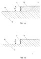
- Figs. 1A and 1B there is an abrupt rising edge 13 of height H between a first smooth surface 10 and a second smooth surface 12.
- the edge 13 may occur, as in Fig. 1A, due to the placement of a sheet 14 on the smooth surface of a body 16.
- the edge 13 may occur in a single body 18.
- the apparatus comprises an illumination unit and a light detector.
- An example of the illumination unit is a laser diode.
- Another example is a laser diode connected to an optical fiber.
- the light detector may have an optical fiber connected to it for collection of the light to be detected.
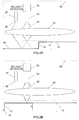
- FIGs. 2A and 2B are schematic illustrations of an apparatus 20 for edge detection, according to a preferred embodiment of the present invention.
- a laser diode 32 is connected to an optical fiber 33.
- a second optical fiber 37 is proximate the optical fiber 33 and is connected to a light detector (not shown).
- the light detector may be, for example, a photodiode that generates electrical current which is translated to a voltage signal by electronic circuitry (not shown).
- Fig. 3 is a schematic illustration of a graph of the voltage signal produced by the electronic circuitry as a function of the position of the apparatus 20 of Fig. 2 relative to the edge.
- the apparatus 20 also comprises a telecentric lens assembly 35.
- a telecentric lens assembly 35 In operation, light from the laser diode 32 is carried through the optical fiber 33, and the light beam 38 emitted from the optical fiber 33 is directed towards the surfaces 10 and 12 by the lens assembly 35.
- the optical fiber 33 of the apparatus 20 is to the left of the edge 13, the light beam 38 is not in focus on the surface 10.
- a significant part of this light is reflected back from the surface 10 towards the lens 35 assembly, and is focused by the lens assembly 35 on the surface end 36 of the optical fiber 37.
- This light collected by the optical fiber 37 is transmitted to the photodiode, and, as shown in Fig. 3 by the voltage measurements 40, 42, 44 and 46, the voltage signal produced by the electronic circuit is relatively strong.
- the optical fiber 33 of the apparatus 20 when the optical fiber 33 of the apparatus 20 is in front of the surface 12, the light beam 38 is in focus on the surface 12. Hence, most of the light reflected back from the surface 12 is focused by the lens assembly 35 onto the surface end of the optical fiber 33. Only a very small portion of the reflected light arrives at the end of the optical fiber 37, and from it through the optical fiber 37 to the photodiode. Therefore, as shown in Fig. 3 by the voltage measurements 48, 50 and 52, the voltage signal produced by the electronic circuit is relatively weak.
- the voltage signal produced by the electronic circuit will change abruptly when the apparatus crosses the edge 13 of the surfaces 10 and 12. If the apparatus 20 is moved from illuminating the surface 10 to illuminating the surface 12, then the position of the apparatus 20 when the voltage drops below a predetermined threshold indicates the location of the edge 13. If the apparatus 20 is moved from illuminating the surface 12 to illuminating the surface 10, then the position of the apparatus 20 when the voltage rises above a predetermined threshold indicates the location of the edge 13.
- the edge detection apparatus of the present invention performs optimally when the distance between the optical fiber 33 and the optical fiber 37 is approximately the same as the height of the edge 13.
- the apparatus and method of the present invention are capable of detecting the edge also when the illuminating light beam has a focal point which is very near but not precisely at the surface 12.
- a particular application of the present invention is to detect the edge of a medium to be exposed in a printing system, the medium mounted on a support which is part of the printing system.
- the printing system may be a platesetter and the medium to be exposed is a plate.
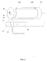
- Fig. 4 is a schematic illustration of a printing system 21, according to a preferred embodiment of the present invention.
- the printing system 21 comprises an optical print head 22, and a plate support 24.
- the support 24 may be a drum or a flat bed.
- the plate may be mounted on the exterior surface of the drum, or on the interior surface of the drum.
- the following discussion will describe the example of an exterior drum for the support 24, although it is understood that any other suitable plate support is included in the scope of the present invention.
- the optical print head 22 is movable along a guiding support 27, as indicated by arrow 28.
- a plate 25 to be exposed by the optical print head 22 is mounted on the drum 24 against two fixed pins 23A and 23B, and is secured to the drum 24 by conventional clamping means (not shown).
- the plate 25 has an edge 29, whose position has to be detected with an accuracy of 20 microns ( ⁇ m) or better.
- the drum 24 rotates on its axis as indicated by arrow 26, while the optical print head 22 moves along the guiding support 27, thereby exposing a plate 25 mounted on the drum 24 in a line by line fashion.
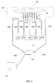
- the optical print head 22 comprises an array of infrared (IR) laser diodes 32, of which, for example, five are referenced 32A - 32E. It will be understood that there can be many more than five laser diodes in the optical print head 22.
- IR infrared
- Each laser diode 32 is attached to a corresponding optical fiber 33A - 33E, known as the writing fibers.
- the attachment may be, for example, a pigtail type attachment, as is known in the art, or any other suitable type of attachment.
- the light emitting ends of the optical fibers 33 are aligned in an assembly 34.
- the optical fibers 33 are aligned in the assembly 34 in a linear array with predetermined spacings therebetween.
- the light from all IR laser diodes 32 which is modulated in accordance to the information representing the image to be printed, is focused on the plate 25 by a telecentric lens assembly 35, as is known in the art. It will be appreciated that any variation of the lens assembly 35 which images the light from the assembly 34 onto the plate 25 is within the scope of the present invention.
- the optical print head 22 comprises two additional optical fibers 37A and 37B positioned on either side of the writing optical fibers 33.
- the other ends of the optical fibers 37A and 37B are connected to a metal housing 41 via connectors 42A and 42B.
- the optical fibers 37A and 37B and the connectors 42A and 42B are already present in the optical print head 22 for the purpose of focussing prior to imaging.
- this is the arrangement of the optical print head for the commercially available platesetter Lotem from Scitex Corporation of Herzliya, Israel.
- the present invention makes use of the existing fiber arrangement in the optical print head of a platesetter in order to perform edge detection of the plate.
- the metal housing 41 contains a photodiode 43.
- the light coming out of either optical fiber 37A or 37B is directed to the surface of the photodiode 43, generating electrical current which is translated to a voltage signal by an electronic circuit 45.
- the edge detection apparatus of the present invention is not sensitive to the plate type.
- two optical fibers 37A and 37B are connected to the metal housing 41 of photodiode 43 in order to provide redundancy. If the laser diode used for edge detection (for example, 32E) fails, the system can continue working by operating the other extreme laser diode (32A) instead of the failed laser diode.
- the connection of both optical fibers 37A and 37B to the same metal housing 41 enables this redundancy.
- the metal housing 41 is specially designed in order to enable detecting by a single photodiode 43 the light coming from both fibers 37A and 37B.
- the fibers 37A and 37B are connected at an angle of 45° relative to the plane of the photodiode 43, and are equidistant from the photodiode 43.
- the throughput For systems such as platesetters, one of the important parameters of the system is its throughput. In order to affect the throughput as little as possible, the time dedicated to plate edge detection should be minimized. Since time is required for the drum to achieve its correct rotational speed, it is preferable to perform the edge detection while the drum is spinning; in this case, the imaging can start immediately after detecting the plate edge.
- a method for detecting the edge of a plate in the printing system of Fig. 4 is performed in two stages.
- the optical print head 22 moves quickly along the guiding support 27 and the edge is detected with low accuracy.
- the optical print head 22 is then moved backward and the second stage begins.
- the optical print head 22 moves a smaller distance in the vicinity of the edge, the optical print head 22 moving along the guiding support 27 at a much lower speed which is dictated by the required detection accuracy.
- the difference in the position of the apparatus between voltage measurements can be as low as 2 - 10 microns ( ⁇ m), and therefore the location of the edge can be detected within the required accuracy of 20 microns ( ⁇ m).
- the location of the edge can be detected with even higher accuracy.
- the apparatus can be used to detect the mounting angle of the plate 25 on the plate support 24.
- Figs. 6A and 6B are schematic illustrations of a plate 25 on a flat bed 24 and a drum 24, respectively.
- the plate 25 is misaligned by an angle of ⁇ .
- the optical print head 22 (Fig. 4) can be moved along the guiding support 27 (Fig. 4) for two lines 60 and 62, thereby detecting the edge at locations 64 and 66, respectively.
- the plate angle a can be calculated from the detected locations 64 and 66.
- the optical print head 22 is moved in a first direction corresponding to line 60, thereby detecting the edge at location 64. Then the optical print head is moved in a second direction transverse to the first direction, thus positioning it over a point of line 62. Finally, the optical print head is moved again in the first direction, now corresponding to line 62, thereby detecting the edge at location 66.
- the plate angle ⁇ can be calculated from the detected locations 64 and 66.
- the optical print head makes a measurement at a point on line 60 and a measurement at a point on line 62.
- the optical print head moves in a first direction parallel to the drum axis, it continues making measurements at points on line 60 and line 62.
- the optical print head crosses the edge at line 60, it detects the edge at location 64.
- the optical print head crosses the edge at line 62, it detects the edge at location 66.
- the plate angle ⁇ can be calculated from the detected locations 64 and 66.
- the edge detection apparatus can be used for detecting the plate edge parallel to the axis of the drum.
- the optical print head 22 does not move, and the drum rotates in front of the optical print head 22.
- the signal of the photodiode changes dramatically.
- the position of the drum while this signal change is detected determines the position of the plate edge parallel to the drum axis.
Landscapes
- Physics & Mathematics (AREA)
- General Physics & Mathematics (AREA)
- Length Measuring Devices By Optical Means (AREA)
- Manufacture Or Reproduction Of Printing Formes (AREA)
- Exposure And Positioning Against Photoresist Photosensitive Materials (AREA)
Applications Claiming Priority (2)
| Application Number | Priority Date | Filing Date | Title |
|---|---|---|---|
| IL13167199A IL131671A0 (en) | 1999-08-31 | 1999-08-31 | Apparatus and method for edge detection |
| IL13167199 | 1999-08-31 |
Publications (2)
| Publication Number | Publication Date |
|---|---|
| EP1081458A2 true EP1081458A2 (fr) | 2001-03-07 |
| EP1081458A3 EP1081458A3 (fr) | 2001-10-24 |
Family
ID=11073199
Family Applications (1)
| Application Number | Title | Priority Date | Filing Date |
|---|---|---|---|
| EP00307250A Withdrawn EP1081458A3 (fr) | 1999-08-31 | 2000-08-23 | Procédé et appareil de détection des bords |
Country Status (3)
| Country | Link |
|---|---|
| EP (1) | EP1081458A3 (fr) |
| CA (1) | CA2316433A1 (fr) |
| IL (1) | IL131671A0 (fr) |
Cited By (11)
| Publication number | Priority date | Publication date | Assignee | Title |
|---|---|---|---|---|
| EP1306213A3 (fr) * | 2001-10-23 | 2004-01-21 | Agfa Corporation | Procédé et appareil pour la détection du bord d'une plaque d'impression monté dans un système d'enrégistrement à tambour |
| DE10307381B3 (de) * | 2003-02-21 | 2004-06-03 | Heidelberger Druckmaschinen Ag | Vorrichtung und Verfahren zur Erkennung der Kante eines Aufzeichnungsmaterials |
| DE10306104A1 (de) * | 2003-02-14 | 2004-09-09 | Heidelberger Druckmaschinen Ag | Vorrichtung und Verfahren zur Erkennung der Kante eines Aufzeichnungsmaterials |
| EP1591241A3 (fr) * | 2004-04-27 | 2005-11-16 | Dainippon Screen Mfg. Co., Ltd. | Appareil d'enregistrement d'images |
| US7033450B2 (en) * | 2002-10-17 | 2006-04-25 | Kodak Graphic Communications Canada Company | Flexographic printing method |
| US7063018B2 (en) | 2003-05-23 | 2006-06-20 | Eastman Kodak Company | Method and apparatus for detecting the edge of an imaging media |
| WO2007019677A1 (fr) * | 2005-08-16 | 2007-02-22 | Kodak Graphic Communications Canada Company | Enregistrement d'une plaque d'impression a l'aide d'une camera |
| WO2008121237A1 (fr) | 2007-03-29 | 2008-10-09 | Eastman Kodak Company | Calage de plaque d'impression utilisant une caméra |
| ITBO20080709A1 (it) * | 2008-11-25 | 2010-05-26 | Bieffebi Societa Per Azioni | Apparato per il controllo di parametri geometrici di gruppi di stampa costituiti da cliché flessografici montati su rispettivi cilindri, da cliché flessografici montati su rispettivi sleeve portacliché e da cilindri/sleeves distributori di inchiostro |
| US7784402B2 (en) | 2007-04-24 | 2010-08-31 | Eastman Kodak Company | Method for loading printing plate on imaging device |
| EP2315289A2 (fr) | 2001-05-23 | 2011-04-27 | Plastic Logic Limited | Formation de motifs au laser pour des dispositifs |
Family Cites Families (3)
| Publication number | Priority date | Publication date | Assignee | Title |
|---|---|---|---|---|
| JPS5877606A (ja) * | 1981-09-04 | 1983-05-11 | エム・ア−・エヌ−ロ−ラント・ドルツクマシ−ネン・アクチエンゲゼルシヤフト | 支持体上の印刷用紙の位置検出装置 |
| CH684656A5 (de) * | 1992-05-06 | 1994-11-15 | Baumer Electric Ag | Verfahren und Vorrichtung zum Erkennen und Auswerten von Kanten an Gegenständen. |
| US5543918A (en) * | 1995-01-06 | 1996-08-06 | International Business Machines Corporation | Through-the-lens confocal height measurement |
-
1999
- 1999-08-31 IL IL13167199A patent/IL131671A0/xx unknown
-
2000
- 2000-08-21 CA CA002316433A patent/CA2316433A1/fr not_active Abandoned
- 2000-08-23 EP EP00307250A patent/EP1081458A3/fr not_active Withdrawn
Cited By (22)
| Publication number | Priority date | Publication date | Assignee | Title |
|---|---|---|---|---|
| EP2315289A2 (fr) | 2001-05-23 | 2011-04-27 | Plastic Logic Limited | Formation de motifs au laser pour des dispositifs |
| EP1306213A3 (fr) * | 2001-10-23 | 2004-01-21 | Agfa Corporation | Procédé et appareil pour la détection du bord d'une plaque d'impression monté dans un système d'enrégistrement à tambour |
| US7033450B2 (en) * | 2002-10-17 | 2006-04-25 | Kodak Graphic Communications Canada Company | Flexographic printing method |
| US7456379B2 (en) | 2003-02-03 | 2008-11-25 | Kodak Graphic Communications Canada Company | Printing plate registration and optical alignment device including locating at least a part of a reference edge in at least one digital camera image |
| DE10306104B4 (de) * | 2003-02-14 | 2005-03-24 | Heidelberger Druckmaschinen Ag | Vorrichtung und Verfahren zur Erkennung der Kante eines Aufzeichnungsmaterials |
| US7057196B2 (en) | 2003-02-14 | 2006-06-06 | Heidelberger Druckmaschinen Aktiengesellschaft | Device and method for detecting the edge of a recording material |
| US7126146B2 (en) | 2003-02-14 | 2006-10-24 | Heidelberger Druckmaschinen Ag | Device and method for detecting the edge of a recording material |
| DE10306104A1 (de) * | 2003-02-14 | 2004-09-09 | Heidelberger Druckmaschinen Ag | Vorrichtung und Verfahren zur Erkennung der Kante eines Aufzeichnungsmaterials |
| US6915743B2 (en) | 2003-02-21 | 2005-07-12 | Heidelberger Druckmaschinen Aktiengesellschaft | Device and method for detecting the edge of a recording material |
| DE10307381B3 (de) * | 2003-02-21 | 2004-06-03 | Heidelberger Druckmaschinen Ag | Vorrichtung und Verfahren zur Erkennung der Kante eines Aufzeichnungsmaterials |
| US7063018B2 (en) | 2003-05-23 | 2006-06-20 | Eastman Kodak Company | Method and apparatus for detecting the edge of an imaging media |
| EP1591241A3 (fr) * | 2004-04-27 | 2005-11-16 | Dainippon Screen Mfg. Co., Ltd. | Appareil d'enregistrement d'images |
| CN1690848B (zh) * | 2004-04-27 | 2010-08-25 | 大日本网目版制造株式会社 | 图像记录装置 |
| US7362347B2 (en) | 2004-04-27 | 2008-04-22 | Dainippon Screen Mfg. Co., Ltd. | Image recording apparatus having a recording drum rotatable with a recording medium mounted peripherally thereof |
| WO2007019677A1 (fr) * | 2005-08-16 | 2007-02-22 | Kodak Graphic Communications Canada Company | Enregistrement d'une plaque d'impression a l'aide d'une camera |
| CN100594127C (zh) * | 2005-08-16 | 2010-03-17 | 加拿大柯达图形通信公司 | 在印刷版上提供配准图像的方法和设备 |
| US7854199B2 (en) | 2007-03-29 | 2010-12-21 | Eastman Kodak Company | Printing plate registration using a camera |
| WO2008121237A1 (fr) | 2007-03-29 | 2008-10-09 | Eastman Kodak Company | Calage de plaque d'impression utilisant une caméra |
| US8148704B2 (en) | 2007-03-29 | 2012-04-03 | Eastman Kodak Company | Printing plate registration using a camera |
| US7784402B2 (en) | 2007-04-24 | 2010-08-31 | Eastman Kodak Company | Method for loading printing plate on imaging device |
| ITBO20080709A1 (it) * | 2008-11-25 | 2010-05-26 | Bieffebi Societa Per Azioni | Apparato per il controllo di parametri geometrici di gruppi di stampa costituiti da cliché flessografici montati su rispettivi cilindri, da cliché flessografici montati su rispettivi sleeve portacliché e da cilindri/sleeves distributori di inchiostro |
| WO2010060884A1 (fr) * | 2008-11-25 | 2010-06-03 | Bieffebi - Societa' Per Azioni | Appareil pour vérifier les paramètres géométriques d’ensembles d’impression constitués de plaques d’impression flexographique montées sur des cylindres respectifs, de plaques d’impression flexographique montées sur des manchons de plaque d’impression respectifs et des cylindres/manchons d’encrage |
Also Published As
| Publication number | Publication date |
|---|---|
| CA2316433A1 (fr) | 2001-02-28 |
| IL131671A0 (en) | 2001-01-28 |
| EP1081458A3 (fr) | 2001-10-24 |
Similar Documents
| Publication | Publication Date | Title |
|---|---|---|
| US4725722A (en) | Automatic focusing method and apparatus utilizing contrasts of projected pattern | |
| US5999245A (en) | Proximity exposure device with distance adjustment device | |
| US5610719A (en) | Displacement detection system | |
| US4232969A (en) | Projection optical system for aligning an image on a surface | |
| EP1306213A2 (fr) | Procédé et appareil pour la détection du bord d'une plaque d'impression monté dans un système d'enrégistrement à tambour | |
| CA2316433A1 (fr) | Appareil et methode de detection de bord | |
| KR19980063666A (ko) | 자동초점조정방법 및 장치 | |
| US6295129B1 (en) | Arrangement and method for marking defects | |
| JPH08219715A (ja) | ウェッブまたはシートのエッジの位置の測定方法および測定装置 | |
| US20080245981A1 (en) | Apparatus and method for edge detection | |
| US7063018B2 (en) | Method and apparatus for detecting the edge of an imaging media | |
| US7362347B2 (en) | Image recording apparatus having a recording drum rotatable with a recording medium mounted peripherally thereof | |
| EP0499778B1 (fr) | Appareil de traitement d'images | |
| KR100361219B1 (ko) | 부품의 연결부 또는 에지부의 위치를 식별하는 방법 및 장치 | |
| EP0883280A2 (fr) | Système d'imagerie avec goupille de posionnement mobile | |
| JPS6239365B2 (fr) | ||
| JP2006317428A (ja) | 面位置検出装置 | |
| US6208366B1 (en) | Optical head having function of detecting positional displacement of photosensitive member and electrophotographic image forming apparatus employing the same | |
| US6697094B2 (en) | Method and apparatus for locating the process postion of a scan line in an electrophotographic machine | |
| JP3462177B2 (ja) | 回転対象物の位置を検出する装置 | |
| US5631738A (en) | Laser ranging system having reduced sensitivity to surface defects | |
| US6850264B2 (en) | Edge detection apparatus and method | |
| JPH09258091A (ja) | レーザー光射出光学ユニットのピント測定方法 | |
| JP2818597B2 (ja) | パターン検査方法 | |
| JP4048163B2 (ja) | 光学式物体識別装置およびそれを用いた印刷装置 |
Legal Events
| Date | Code | Title | Description |
|---|---|---|---|
| PUAI | Public reference made under article 153(3) epc to a published international application that has entered the european phase |
Free format text: ORIGINAL CODE: 0009012 |
|
| AK | Designated contracting states |
Kind code of ref document: A2 Designated state(s): AT BE CH CY DE DK ES FI FR GB GR IE IT LI LU MC NL PT SE Kind code of ref document: A2 Designated state(s): BE DE DK FR GB |
|
| AX | Request for extension of the european patent |
Free format text: AL;LT;LV;MK;RO;SI |
|
| PUAL | Search report despatched |
Free format text: ORIGINAL CODE: 0009013 |
|
| AK | Designated contracting states |
Kind code of ref document: A3 Designated state(s): AT BE CH CY DE DK ES FI FR GB GR IE IT LI LU MC NL PT SE |
|
| AX | Request for extension of the european patent |
Free format text: AL;LT;LV;MK;RO;SI |
|
| RIC1 | Information provided on ipc code assigned before grant |
Free format text: 7G 01B 11/06 A, 7G 01B 11/02 B |
|
| 17P | Request for examination filed |
Effective date: 20020121 |
|
| RAP1 | Party data changed (applicant data changed or rights of an application transferred) |
Owner name: CREO IL. LTD. |
|
| AKX | Designation fees paid |
Free format text: BE DE DK FR GB |
|
| STAA | Information on the status of an ep patent application or granted ep patent |
Free format text: STATUS: THE APPLICATION HAS BEEN WITHDRAWN |
|
| 18W | Application withdrawn |
Withdrawal date: 20021122 |