EP1081507A2 - Vorrichtung zum Auslesen von in einer Speicherschicht abgespeicherten Informationen durch Anregungsstrahlung und Emfangsmittel - Google Patents
Vorrichtung zum Auslesen von in einer Speicherschicht abgespeicherten Informationen durch Anregungsstrahlung und Emfangsmittel Download PDFInfo
- Publication number
- EP1081507A2 EP1081507A2 EP00116750A EP00116750A EP1081507A2 EP 1081507 A2 EP1081507 A2 EP 1081507A2 EP 00116750 A EP00116750 A EP 00116750A EP 00116750 A EP00116750 A EP 00116750A EP 1081507 A2 EP1081507 A2 EP 1081507A2
- Authority
- EP
- European Patent Office
- Prior art keywords
- storage layer
- receiving means
- phosphor layer
- radiation source
- radiation
- Prior art date
- Legal status (The legal status is an assumption and is not a legal conclusion. Google has not performed a legal analysis and makes no representation as to the accuracy of the status listed.)
- Granted
Links
Images

Classifications
-
- G—PHYSICS
- G01—MEASURING; TESTING
- G01T—MEASUREMENT OF NUCLEAR OR X-RADIATION
- G01T1/00—Measuring X-radiation, gamma radiation, corpuscular radiation, or cosmic radiation
- G01T1/16—Measuring radiation intensity
- G01T1/20—Measuring radiation intensity with scintillation detectors
- G01T1/2012—Measuring radiation intensity with scintillation detectors using stimulable phosphors, e.g. stimulable phosphor sheets
- G01T1/2014—Reading out of stimulable sheets, e.g. latent image
Definitions
- the present invention relates to a device for reading out in a Information stored in the storage layer according to the preamble of Claim 1.
- an object for example a patient, by means of X-ray radiation, generates an image that is in a Storage layer is stored as a latent image.
- a storage layer mostly a phosphor support is used.
- the stored x-ray image becomes the storage layer excited by a radiation source. It then emits on the basis of this Excitation light that has an intensity corresponding to the stored x-ray image having.
- the light emitted by the storage layer is received by a receiving means and then in electrical Signals converted so that the X-ray image stored in the storage layer can then be made visible.
- the X-ray image can, for example, be displayed directly on a monitor or on wrote a photographic X-ray film that can be used especially for X-ray images become.
- a device for reading out in a storage layer information stored is, for example, from the previously published Patent application DE 197 52 925 A1 known. In this device the light emitted by the storage layer very precisely onto the receiving means be mapped. The distance should increase the degree of compactness be small between the storage layer and the receiving means.
- the object of the present invention is to provide good quality the reproduction of information stored in a storage layer enable.
- a predetermined distance can be achieved by the spacer provided according to the invention advantageously as constant as possible and furthermore very small be adjustable so that a large amount of the excited by the storage layer emitted radiation can be detected by the receiving means. Due to the spacer provided according to the invention, occurring unwanted changes in distance can be corrected very quickly. Such changes in distance can occur, for example, when the Surface of the image plate has inaccuracies due to the manufacturing process or but from the outside shocks or impacts on the device according to the invention that also affect the distance between the receiving means and the storage layer impact.
- the spacer advantageously contains an air layer.
- Air layers are very small distances between the storage layer and the receiving means adjustable.
- the air layer can be very precise by means of air nozzles which are contained in the spacer. These air nozzles are connected to an air supply.
- the device has transparent carrier material on which the storage layer is applied.
- the receiving means is then on one side and the radiation source on the other Side of the storage layer arranged. Between the radiation source and a further spacer can then be provided in the storage layer. This is particularly advantageous if between the storage layer and the radiation source has a relative movement to excite the storage layer is carried out because touching the radiation source and the storage layer can be avoided.
- the device a power means, in particular a spring, with which a force from the receiving means can be exercised towards the storage layer.
- a power means in particular a spring, with which a force from the receiving means can be exercised towards the storage layer.
- Fig. 1 shows a schematic representation of a first embodiment a reading device 1 according to the invention with a phosphor layer 10, which is arranged on a transparent carrier material 9.
- the Phosphor layer 10 serves as a storage layer in which by means of X-rays a latent x-ray image was saved. This latent x-ray image can read out from the phosphor layer 10 by means of the reading device 1 and for Presentation can be prepared on a monitor or an X-ray film.
- the reading device 1 has a radiation source 2, which is designed here as a line light source and contains a multiplicity of laser diodes arranged next to one another.
- the radiation source 2 contains 4,096 laser diodes arranged parallel to one another in a line. With these laser diodes, a row of the phosphor layer 10 can be excited to emit radiation.
- 1 shows a laser radiation 20 which is emitted by one of the laser diodes of the radiation source 2 in the direction of the phosphor layer 10.
- the laser diodes of the radiation source 2 are aligned as perpendicularly as possible to the phosphor layer 10 so that the radiation emitted by the individual laser diodes strikes the phosphor layer 10 directly.
- the radiation source 2 extends essentially over the entire width of the phosphor layer 10, about which information can be stored.
- the radiation source 2 configured with laser diodes
- another radiation source can also be used.
- 3 shows an embodiment with a so-called flying spot 'laser radiation source.
- the line-shaped radiation source 2 can be used to excite a line of the phosphor layer 10 for emitting radiation, which emits information corresponding to the part of the x-ray image contained in this excited line.
- the reading device 1 also has one charge coupled device "(CCD) line.
- the CCD line 3 contains a multiplicity of photodetectors arranged parallel to one another in a line. With the aid of these photodetectors, a photoelectric conversion of the received light radiation can be carried out.
- Each photodetector represents a point element of the receiving means and can receive a light radiation emitted from one of the excited points of the phosphor layer 10. In the present exemplary embodiment according to FIG. 1, 3 4 096 individual photodetectors are therefore provided in the CCD line.
- the optical waveguide bundle 5 contains a multiplicity of optical waveguides arranged next to one another in parallel, which detect the radiation emitted by the individual excited points of the phosphor layer 10 and feed it to the individual photodetectors of the CCD line 3.
- 1 shows a photodetector 4 that receives the radiation that is emitted by the phosphor layer 10 due to the laser radiation 20 emitted by one of the laser diodes of the radiation source 2.
- At least one optical waveguide is assigned to each of the photodetectors of the CCD line 3.
- optical waveguide bundles 5 which can be used for imaging and transporting the light radiation emitted by the phosphor layer to the photodetectors of the CCD line 5, are known and can be used, for example, as so-called fused fiber-optic faceplates "from Schott.
- the optical fiber bundle 5 can be doped so that it simultaneously acts as a filter for the laser radiation emitted by the laser radiation source 2 and passes through the phosphor layer 10.
- other imaging agents can also be used. such as a so-called self-lens array or a corresponding arrangement with microlenses can be used.
- the fiber optic bundle 5 and the CCD line 3 represent the receiving means here for receiving the light radiation emitted by the phosphor layer 10 CCD time 3 and fiber optic bundle 5 are on that side of the carrier material 9 arranged on which the phosphor layer 10 is attached is. This allows the optical fiber bundle 5 to be very close to the surface of the Phosphor layer 10 for better detection of the phosphor layer 10 output light radiation may be arranged.
- the Radiation source 2 On the other, opposite The side of the carrier material 9 without a phosphor layer is the Radiation source 2 arranged. The output from the radiation source 2 Laser radiation for exciting the phosphor layer 10 is, if possible, without Scattering, through the carrier material 9 to the phosphor layer 10 directed.
- the optical fiber bundle 5 is placed directly on the CCD line 3 and advantageously attached as close as possible to the phosphor layer 10, so much light radiation from the phosphor layer after its Excitation is emitted to be able to collect.
- an air bearing 30 is arranged between the surface of the phosphor layer 10 and CCD line 3.
- This air bearing 30 serves as a spacer to set a predetermined distance between the Optical fiber bundle 5 and the surface of the phosphor layer 10.
- the air bearing 30 has a plurality of air nozzles 31 arranged parallel to one another. These air nozzles 31 are connected to an air inlet 33 via air channels 34. Air is supplied to the air nozzles 31 via the air inlet 33 and the air channels 34. This supplied air is from the air nozzles 31 in the direction of the phosphor layer 10 issued with one print. This forms between the Air nozzles and the phosphor layer 10 a predetermined distance.
- This distance leads to an air gap 28 between the optical fiber bundle 5 and the phosphor layer 10.
- the distance should be as small as possible. Because of the engagement the air bearing 30, the very small distance of about 10 microns can be set. A high optical collection efficiency when detecting the from the phosphor layer 10 light output is therefore guaranteed, which is excellent Quality of the reproduction of the read X-ray image enables.
- an air bearing can also other types of bearings, such. B. plain bearings or roller bearings, or a combination of different types of bearings become.
- the air nozzles 31 are arranged on both sides of the optical fiber bundle 5 in the exemplary embodiment.
- the shape and size of the air bearing 30 can largely be chosen freely.
- the air bearing 30 can, for example, extend along the entire width of the line to be read out or, as a relatively small air bearing, can be attached only to the end faces of the receiving means, ie the CCD line 3 and the optical fiber bundle 5.
- the air bearing 30 can advantageously be designed as a bearing which can be displaced along the row direction. This can cause manufacturing inaccuracies and small Deflections "of the receiving means, which can occur due to its weight, are compensated for.
- the air gap 28 is essentially formed by a balance of forces. This is caused by a compressive force in the direction generated by the air layer of the optical fiber bundle 5 and by the gravitational forces of the CCD line 3, the Air supply system 33, 34 and the optical fiber bundle 5 in the direction of Phosphor layer 10.
- a separate power means can be provided.
- this force means a spring 21, in particular a plate spring. This Spring 21 is here between the CCD line 3 and one not shown Outer border, e.g. B. a housing, the reader 1 attached.
- the spring 21 is designed so that the of her exerted force acts in a force direction B in the direction of the phosphor layer 10 and thus increases the contact pressure on the air layer in the air gap 28.
- the surface of the phosphor layer 10 is additionally smoothed, what is setting the given distance between phosphor layer 10 and fiber optic bundle 5 further improved.
- the Air bearing 30 can be both vertical or horizontal or other Adjust the position of the reading device 1 the air gap 28 exactly.
- the radiation source 2 For reading out the entire phosphor layer 10 by means of the reading device 1 the radiation source 2 together with that on the opposite side of the Phosphor layer 10 arranged receiving means with CCD line 3, optical fiber bundle 5 and air bearing 30 shifted line by line in a transport direction A. Receiving means 3, 5 and radiation source 2 are advantageous for this rigidly connected. Thus, one row of the phosphor layer 10 read out one after the other and the information stored accordingly in it detected and converted into electrical signals.
- Air bearings that can be used in the reading device 1 to generate a distance between the receiving means and the radiation source 2 are known in principle and can be obtained, for example, from AeroLas GmbH, Unterhaching, Germany. Such air bearings are also in the book Gutlagerache "by Wilfried J. Bartz et al., Expert-Verlag, 2nd edition, 1993.
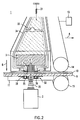
- Fig. 2 shows a schematic representation of the second embodiment of the Reading device 1.
- a further air bearing 32 which is between the transparent Carrier material 9 and the radiation source 2 is arranged.
- the structure this further air bearing 32 corresponds essentially to that of Air bearing 30, which is between the phosphor layer 10 and the CCD line 3 or the optical fiber bundle 5 is arranged. It can have an independent, Air supply, not shown, can be supplied with air. But it is also possible to couple the further air bearing 32 to the air supply for the air bearing 30.
- the further air bearing 32 is integrated here in a pad 11 on which u. a. the Radiation source 2 is arranged.
- the pad 11 serves to guide the transparent Carrier material 9 and the phosphor layer 10 applied to it. This is particularly important if the transparent carrier material 9 and the phosphor layer 10 applied to it when reading out the in the phosphor layer 10 stored X-ray image is moved and the radiation source 2, d. H. the CCD line 3 together with the optical fiber bundle 5, in the Reading device 1 is fixed.
- the further air bearing 32 which is embedded in the base 11, preferably contains two balls 35 and 36. These two balls 35 and 36 are used for Closing air nozzles present in the further air bearing 32. Becomes a phosphor layer together with transparent carrier material 9 in the reading device 1 inserted, the two balls 35 and 36 are down pressed and supplied air can flow out of the air nozzles. Should, in particular by vibrations, by bending the phosphor layer 10 and of the carrier material 9 or by increased air supply from the air nozzles and thus increased air pressure, the air gap between the base material 9 and the base 11 enlarge, so the balls 35 and 36 automatically at least partially pressed back into the outlet openings of the air nozzles.
- the contact pressure of the CCD line 3 together with the optical fiber bundle 5 on the phosphor layer 10 is particularly large. This will make the phosphor layer 10 pressed onto the transparent carrier material 9 when it is read out and smoothed. Thickness fluctuations of the phosphor layer 10 can at least partially corrected.
- the distance 28 can be set exactly on the x-ray image. The between that Carrier material 9 and the pad 11 to be complied with and via the further air bearing 32 distance to be set does not necessarily have to be set so precisely become like the distance between the phosphor layer 10 and the optical fiber bundle 5.
- the reading device 1 For driving the phosphor layer 10 and the transparent carrier material 9 in the transport direction A, the reading device 1 contains one above the phosphor layer 10 arranged first transport roller 14 and one below the transparent Carrier material 9 arranged second transport roller 15. These can controlled by a drive motor 13 with which they are connected and be rotated. This can advance the phosphor layer 10 in Direction A can be effected. However, other types of drive can also be used.
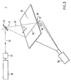
- FIG. 3 shows a schematic illustration of the third exemplary embodiment of the present invention.
- the reading device 1 is here as a so-called. flying spot "laser system.
- the basic structure of such flying spot "laser system is already known, for example from European patent application EP 0 777 148 A1.
- FIG. 3 shows a laser 50 which emits a laser beam 52.
- This laser beam 52 is applied to a collimator 51 rotating polygon mirror 53 about an axis of rotation D.
- the polygon mirror 53 directs the laser beam 52 in the direction of a phosphor layer 54.
- the laser beam 52 is guided along a line propagation direction C.
- Each point of a line of the Phosphor layer 54 is excited and the phosphor layer 54 is fed line by line so that it is read line by line
- the light emitted from the phosphor layer 54 due to the excitation by means of the laser beam 52 is collected by a fiber cross-section converter 57 which contains light guides and fed to a photodetector 58. In this way, the Roe stored in the phosphor layer 54 becomes The image is read out point by line and line by line.
- the reading device 1 according to the third embodiment a third air bearing 56 on the long side of the fiber cross-sectional converter 57 along line direction C is attached.
- the third air bearing 56 is essentially configured like the two air bearings 30 and 32 according to the first and second embodiments.
- a small air gap 59 is formed. This in turn can prevent that phosphor layer 54 and fiber cross-section converter 57 during Touch the feed movement of the phosphor layer 54. Because of the air gap 59 is also in the reading device 1 according to the third embodiment the smallest possible and constant distance between phosphor layer 54 and fiber cross-section converter 57 adjustable.
- the reading device 1 can be used independently, e.g. B. designed in the form of an X-ray cassette be in which all necessary, described components for reading the Phosphor layer are included.
- Both the phosphor layer and the radiation source and receiving means can be installed in such an X-ray examination table.
Landscapes
- Physics & Mathematics (AREA)
- Health & Medical Sciences (AREA)
- Life Sciences & Earth Sciences (AREA)
- General Physics & Mathematics (AREA)
- High Energy & Nuclear Physics (AREA)
- Molecular Biology (AREA)
- Spectroscopy & Molecular Physics (AREA)
- Measurement Of Radiation (AREA)
- Facsimile Scanning Arrangements (AREA)
- Conversion Of X-Rays Into Visible Images (AREA)
- Apparatus For Radiation Diagnosis (AREA)
- Optical Recording Or Reproduction (AREA)
Abstract
Description
- Fig. 1
- ein erstes Ausführungsbeispiel der erfindungsgemäßen Vorrichtung mit einem Abstandsmittel zwischen Speicherschicht und Empfangsmittel,
- Fig. 2
- ein zweites Ausführungsbeispiel der erfindungsgemäßen Vorrichtung mit einem weiteren Abstandsmittel zwischen Strahlungsquelle und Speicherschicht und
- Fig. 3
- ein drittes Ausführungsbeispiel der erfindungsgemäßen Vorrichtung mit
einem sogenannten flying spot"-Lasersystem als Strahlungsquelle.

Claims (12)
- Vorrichtung (1) zum Auslesen von in einer Speicherschicht (10) abgespeicherten Informationen mitdadurch gekennzeichnet, daßeiner Strahlungsquelle (2) zum Aussenden von einer Anregungsstrahlung (20),einem Empfangsmittel (3) zum Empfangen einer von der Speicherschicht (10) ausgesandten Emissionsstrahlung undeinem Antriebsmittel (13, 14, 15) zum Ausführen einer Relativbewegung zwischen dem Empfangsmittel (3) und der Speicherschicht (10),
zwischen dem Empfangsmittel (3) und der Speicherschicht (10) ein Abstandsmittel (30, 56) zum Einstellen eines vorgegebenen Abstandes beim Ausführen der Relativbewegung zwischen dem Empfangsmittel (3) und der Speicherschicht (10) angeordnet ist. - Vorrichtung nach Anspruch 1, dadurch gekennzeichnet, daß mit dem Abstandsmittel (30, 56) eine Luftschicht zwischen dem Empfangsmittel (3) und der Oberfläche der Speicherschicht (10) erzeugbar ist.
- Vorrichtung nach Anspruch 2, dadurch gekennzeichnet, daß das Abstandsmittel (30, 56) Luftdüsen (31) enthält.
- Vorrichtung nach einem der vorhergehenden Ansprüche, dadurch gekennzeichnet, daß sie ein transparentes Trägermaterial (9) enthält, auf das die auszulesende Speicherschicht (10) aufgebracht ist, und die Strahlungsquelle (2) auf derjenigen Seite des Trägermaterials (9) angeordnet ist, die der Speicherschicht (10) abgewandt ist, und das Empfangsmittel (3) auf derjenigen Seite des Trägermaterials (9) angeordnet ist, die der Speicherschicht (10) zugewandt ist.
- Vorrichtung nach einem der vorhergehenden Ansprüche, dadurch gekennzeichnet, daß sie ein weiteres Abstandsmittel (32) aufweist, das zwischen Strahlungsquelle (2) und Speicherschicht (10) angeordnet ist.
- Vorrichtung nach einem der vorhergehenden Ansprüche, dadurch gekennzeichnet, daß die Speicherschicht (10) fest in der Vorrichtung (1) angeordnet ist.
- Vorrichtung nach einem der vorhergehenden Ansprüche, dadurch gekennzeichnet, daß das Empfangsmittel (3) ein optisches Abbildungsmittel (5) aufweist, mit dem von der angeregten Speicherschicht (10) ausgesandte Emissionsstrahlung erfaßbar ist.
- Vorrichtung nach Anspruch 7, dadurch gekennzeichnet, daß das Abbildungsmittel (5) Lichtwellenleiter aufweist.
- Vorrichtung nach einem der vorhergehenden Ansprüche, dadurch gekennzeichnet, daß die Strahlungsquelle (2) eine Linienlichtquelle zum Anregen einer Zeile der Speicherschicht (10) ist und das Empfangsmittel (3) eine Vielzahl von Punktelementen (4) zum punktweisen Empfangen von Emissionsstrahlung aufweist, wobei von der angeregten Zeile der Speicherschicht (10) ausgesandte Emissionsstrahlung durch die Punktelemente (4) gleichzeitig empfangbar ist.
- Vorrichtung nach einem der vorhergehenden Ansprüche, dadurch gekennzeichnet, daß sie ein Kraftmittel (21) aufweist, mit dem eine Kraft von dem Empfangsmittel (3, 5) auf das Abstandsmittel (30, 56) in Richtung der Speicherschicht (10) ausgeübt werden kann.
- Vorrichtung nach Anspruch 10, dadurch gekennzeichnet, daß das Kraftmittel (21) eine Feder aufweist.
- Vorrichtung nach Anspruch 13, dadurch gekennzeichnet, daß die Strahlungsquelle (2) und das Empfangsmittel (3) starr miteinander verbunden sind
Applications Claiming Priority (2)
| Application Number | Priority Date | Filing Date | Title |
|---|---|---|---|
| DE19937416A DE19937416C2 (de) | 1999-08-07 | 1999-08-07 | Vorrichtung zum Auslesen von in einer Speicherschicht abgespeicherten Informationen |
| DE19937416 | 1999-08-07 |
Publications (3)
| Publication Number | Publication Date |
|---|---|
| EP1081507A2 true EP1081507A2 (de) | 2001-03-07 |
| EP1081507A3 EP1081507A3 (de) | 2002-04-03 |
| EP1081507B1 EP1081507B1 (de) | 2007-07-25 |
Family
ID=7917632
Family Applications (1)
| Application Number | Title | Priority Date | Filing Date |
|---|---|---|---|
| EP00116750A Expired - Lifetime EP1081507B1 (de) | 1999-08-07 | 2000-08-03 | Vorrichtung zum Auslesen von in einer Speicherschicht abgespeicherten Informationen durch Anregungsstrahlung und Empfangsmittel |
Country Status (4)
| Country | Link |
|---|---|
| US (1) | US6703636B1 (de) |
| EP (1) | EP1081507B1 (de) |
| AT (1) | ATE368234T1 (de) |
| DE (2) | DE19937416C2 (de) |
Cited By (4)
| Publication number | Priority date | Publication date | Assignee | Title |
|---|---|---|---|---|
| EP1378767A1 (de) * | 2002-07-02 | 2004-01-07 | Agfa-Gevaert AG | Vorrichtung und Verfahren zum Auslesen von in einer Speicherschicht abgespeicherter Information |
| EP1378765A1 (de) * | 2002-07-02 | 2004-01-07 | Agfa-Gevaert AG | Vorrichtung und Verfahren zum Auslesen von in einer Speicherschicht abgespeicherter Information |
| EP1378766A1 (de) * | 2002-07-02 | 2004-01-07 | Agfa-Gevaert AG | Vorrichtung und Verfahren zum Auslesen von in einer Speicherschicht abgespeicherter Information |
| US6800870B2 (en) | 2000-12-20 | 2004-10-05 | Michel Sayag | Light stimulating and collecting methods and apparatus for storage-phosphor image plates |
Families Citing this family (2)
| Publication number | Priority date | Publication date | Assignee | Title |
|---|---|---|---|---|
| EP1640801B1 (de) * | 2004-09-22 | 2008-08-20 | Agfa-Gevaert HealthCare GmbH | Vorrichtung und Verfahren zum Auslesen von in einer Speicherleuchtstoffplatte gespeicherten Röntgeninformationen |
| DE502005007861D1 (de) * | 2005-12-29 | 2009-09-17 | Agfa Gevaert Healthcare Gmbh | Antriebsvorrichtung für eine optische Abtasteinrichtung |
Family Cites Families (19)
| Publication number | Priority date | Publication date | Assignee | Title |
|---|---|---|---|---|
| DE6931624U (de) | 1969-08-07 | 1970-01-15 | Wilhelm Grinke | Vorrichtung zum reinigen von mit zement- oder kalkmoertel behafteten bauhoelzern sowie schaltafeln und stahlschalung. |
| US4346295A (en) | 1978-12-26 | 1982-08-24 | Fuji Photo Film Co., Ltd. | Radiation image read out device |
| US4661704A (en) | 1985-07-12 | 1987-04-28 | North American Philips Corporation | Image recording and readout device based on light-stimulable phosphors |
| DE3763602D1 (de) | 1986-03-10 | 1990-08-16 | Fuji Photo Film Co Ltd | Vorrichtung zur wiedergabe von strahlungsbildern. |
| US4778995A (en) | 1987-05-12 | 1988-10-18 | Eastman Kodak Company | Stimulable phosphor imaging apparatus |
| DE3728750A1 (de) * | 1987-08-28 | 1989-03-09 | Philips Patentverwaltung | Vorrichtung zum auslesen eines speicherphosphor-aufzeichnungstraegers |
| DE3731203A1 (de) * | 1987-09-17 | 1989-03-30 | Agfa Gevaert Ag | Verfahren zur handhabung von roentgenaufnahmekassetten mit einer phosphorbeschichteten folie und zur durchfuehrung des verfahrens geeignete lesestation |
| US5309255A (en) * | 1992-02-28 | 1994-05-03 | Eastman Kodak Company | Laser beam environment isolation housing |
| US5376806A (en) * | 1993-06-30 | 1994-12-27 | Eastman Kodak Company | Storage phosphor reader having storage phosphor size and exposure speed detection |
| US5877508A (en) * | 1993-09-20 | 1999-03-02 | Fuji Photo Film Co., Ltd. | Radiation image storage panel |
| FI99074C (fi) | 1995-11-21 | 1997-09-25 | Planmed Oy | Menetelmä ja laite digitaaliseen kuvantamiseen tarkoitetun kameran anturijärjestelmän muodostamiseksi |
| JP3394375B2 (ja) * | 1995-12-01 | 2003-04-07 | 富士写真フイルム株式会社 | 放射線画像読取装置 |
| DE19752925C2 (de) * | 1997-11-28 | 2003-11-27 | Agfa Gevaert Ag | Vorrichtung zum Auslesen von einer in einem Phosphorträger abgespeicherten Information und Röntgenkassette |
| DE19859747C1 (de) * | 1998-12-23 | 2000-02-24 | Agfa Gevaert Ag | Vorrichtung und Verfahren zum Auslesen von in einer Phosphorschicht abgespeicherten Informationen |
| DE19922345B4 (de) * | 1999-05-14 | 2005-07-28 | Siemens Ag | Vorrichtung zur Auslesung einer Speicherleuchtstoffplatte |
| US6476406B1 (en) * | 1999-06-22 | 2002-11-05 | Agfa-Gevaert | Devices equipped with tribostimulable storage phosphors |
| US6420724B1 (en) * | 1999-06-22 | 2002-07-16 | Agfa-Gevaert | Method of image formation, dosimetry and personal monitoring |
| EP1065525A3 (de) * | 1999-07-02 | 2006-04-05 | Agfa-Gevaert | Vorrichtung zum Auslesen von Strahlungsbildern |
| JP3952117B2 (ja) * | 2000-01-21 | 2007-08-01 | 富士フイルム株式会社 | 放射線画像読取装置 |
-
1999
- 1999-08-07 DE DE19937416A patent/DE19937416C2/de not_active Expired - Fee Related
-
2000
- 2000-07-31 US US09/628,579 patent/US6703636B1/en not_active Expired - Fee Related
- 2000-08-03 AT AT00116750T patent/ATE368234T1/de not_active IP Right Cessation
- 2000-08-03 EP EP00116750A patent/EP1081507B1/de not_active Expired - Lifetime
- 2000-08-03 DE DE50014505T patent/DE50014505D1/de not_active Expired - Fee Related
Cited By (9)
| Publication number | Priority date | Publication date | Assignee | Title |
|---|---|---|---|---|
| US6800870B2 (en) | 2000-12-20 | 2004-10-05 | Michel Sayag | Light stimulating and collecting methods and apparatus for storage-phosphor image plates |
| US7589341B2 (en) | 2000-12-20 | 2009-09-15 | Michel Sayag | Light stimulating and collecting methods and apparatus for storage-phosphor image plates |
| US7825394B2 (en) | 2000-12-20 | 2010-11-02 | Michel Sayag | Light stimulating and collecting methods and apparatus for storage-phosphor image plates |
| EP1378767A1 (de) * | 2002-07-02 | 2004-01-07 | Agfa-Gevaert AG | Vorrichtung und Verfahren zum Auslesen von in einer Speicherschicht abgespeicherter Information |
| EP1378765A1 (de) * | 2002-07-02 | 2004-01-07 | Agfa-Gevaert AG | Vorrichtung und Verfahren zum Auslesen von in einer Speicherschicht abgespeicherter Information |
| EP1378766A1 (de) * | 2002-07-02 | 2004-01-07 | Agfa-Gevaert AG | Vorrichtung und Verfahren zum Auslesen von in einer Speicherschicht abgespeicherter Information |
| US6969007B2 (en) | 2002-07-02 | 2005-11-29 | Agfa-Gevaert Aktiengesellschaft | Device and method for reading out information stored in a storage layer |
| US6998633B2 (en) | 2002-07-02 | 2006-02-14 | Agfa-Gevaert Healthcare Gmbh | Device and method for reading out information stored in a storage layer |
| US7342243B2 (en) | 2002-07-02 | 2008-03-11 | Agfa-Gevaert Healthcare Gmbh | Device and method for reading out information stored in a storage layer |
Also Published As
| Publication number | Publication date |
|---|---|
| DE19937416A1 (de) | 2001-02-22 |
| DE50014505D1 (de) | 2007-09-06 |
| EP1081507A3 (de) | 2002-04-03 |
| US6703636B1 (en) | 2004-03-09 |
| DE19937416C2 (de) | 2002-11-14 |
| ATE368234T1 (de) | 2007-08-15 |
| EP1081507B1 (de) | 2007-07-25 |
Similar Documents
| Publication | Publication Date | Title |
|---|---|---|
| DE19859747C1 (de) | Vorrichtung und Verfahren zum Auslesen von in einer Phosphorschicht abgespeicherten Informationen | |
| EP1034443B1 (de) | Vorrichtung zum auslesen von einer in einem phosphorträger abgespeicherten information und röntgenkassette | |
| DE19751545B4 (de) | Strahlungstiefendosismessvorrichtung | |
| EP0025956B1 (de) | Optische Vorrichtung zum berührungslosen Schreiben | |
| DE4235549C2 (de) | Gerät zum Justieren einer Lichtquelleneinheit | |
| EP1111407A2 (de) | Vorrichtung zum Auslesen von in einer Speicherschicht abgespeicherten Informationen und Röntgenkassette | |
| DE102012101568A1 (de) | Zweidimensionales Kollimatormodul, Röntgendetektor und Röntgen-CT-Vorrichtung | |
| DE19827423A1 (de) | Zweidimensionale Laserdiodenanordnung | |
| DE102014117251A1 (de) | Röntgentopographievorrichtung | |
| DE3739964A1 (de) | Led-anordnungs-kopf | |
| EP1081507B1 (de) | Vorrichtung zum Auslesen von in einer Speicherschicht abgespeicherten Informationen durch Anregungsstrahlung und Empfangsmittel | |
| EP1691216A1 (de) | Radiographiesystem und Verfahren zur Aufzeichnung von Röntgenaufnahmen in Speicherleuchtstoffschichten | |
| EP1804081B1 (de) | Vorrichtung zum Auslesen von in einer Speicherleuchtstoffschicht abgespeicherten Röntgeninformationen sowie Radiografiemodul | |
| EP1691215B1 (de) | Auslesevorrichtung und Verfahren zum Auslesen von in Speicherleuchtstoffschichten gespeicherten Röntgenaufnahmen | |
| EP1378766B1 (de) | Vorrichtung und Verfahren zum Auslesen von in einer Speicherschicht abgespeicherter Information | |
| EP1804082B1 (de) | Vorrichtung zum Auslesen von in einer Speicherleuchtstoffschicht abgespeicherten Röntgeninformationen sowie Radiografiemodul | |
| EP1298458B1 (de) | Abbildungsvorrichtung zum Abbilden eines länglichen Gegenstandes | |
| EP1378767B1 (de) | Vorrichtung und Verfahren zum Auslesen von in einer Speicherschicht abgespeicherter Information | |
| DE10042605A1 (de) | Bildinformationslesevorrichtung mit Mitteln zum Gleichmäßig-Halten des Pegels einer zu erfassenden Lichtmenge | |
| DE69328455T2 (de) | Fiberoptischer Abtaster für eine Phosphoreszenzbildspeicherplatte | |
| DE102004031097B4 (de) | Lasermessgerät | |
| EP1378765B1 (de) | Vorrichtung und Verfahren zum Auslesen von in einer Speicherschicht abgespeicherter Information | |
| DE60013738T2 (de) | Leuchtstoffträger mit verbessertem Leuchtwirkungsgrad | |
| EP1895324B1 (de) | Verfahren und Vorrichtung zum Auslesen von in einer Speicherleuchtstoffplatte gespeicherten Röntgeninformationen | |
| EP3217408A2 (de) | Fokussierungsmodul für einen formfilter und formfilter zum einstellen einer räumlichen intensitätsverteilung eines röntgenstrahls |
Legal Events
| Date | Code | Title | Description |
|---|---|---|---|
| PUAI | Public reference made under article 153(3) epc to a published international application that has entered the european phase |
Free format text: ORIGINAL CODE: 0009012 |
|
| AK | Designated contracting states |
Kind code of ref document: A2 Designated state(s): AT BE CH CY DE DK ES FI FR GB GR IE IT LI LU MC NL PT SE |
|
| AX | Request for extension of the european patent |
Free format text: AL;LT;LV;MK;RO;SI |
|
| PUAL | Search report despatched |
Free format text: ORIGINAL CODE: 0009013 |
|
| AK | Designated contracting states |
Kind code of ref document: A3 Designated state(s): AT BE CH CY DE DK ES FI FR GB GR IE IT LI LU MC NL PT SE |
|
| AX | Request for extension of the european patent |
Free format text: AL;LT;LV;MK;RO;SI |
|
| 17P | Request for examination filed |
Effective date: 20021004 |
|
| AKX | Designation fees paid |
Free format text: AT BE CH CY DE DK ES FI FR GB GR IE IT LI LU MC NL PT SE |
|
| 17Q | First examination report despatched |
Effective date: 20040621 |
|
| RAP1 | Party data changed (applicant data changed or rights of an application transferred) |
Owner name: AGFA-GEVAERT HEALTHCARE GMBH |
|
| GRAP | Despatch of communication of intention to grant a patent |
Free format text: ORIGINAL CODE: EPIDOSNIGR1 |
|
| GRAS | Grant fee paid |
Free format text: ORIGINAL CODE: EPIDOSNIGR3 |
|
| GRAA | (expected) grant |
Free format text: ORIGINAL CODE: 0009210 |
|
| AK | Designated contracting states |
Kind code of ref document: B1 Designated state(s): AT BE CH CY DE DK ES FI FR GB GR IE IT LI LU MC NL PT SE |
|
| REG | Reference to a national code |
Ref country code: GB Ref legal event code: FG4D Free format text: NOT ENGLISH |
|
| GBT | Gb: translation of ep patent filed (gb section 77(6)(a)/1977) |
Effective date: 20070725 |
|
| REG | Reference to a national code |
Ref country code: CH Ref legal event code: EP |
|
| REG | Reference to a national code |
Ref country code: IE Ref legal event code: FG4D Free format text: LANGUAGE OF EP DOCUMENT: GERMAN |
|
| REF | Corresponds to: |
Ref document number: 50014505 Country of ref document: DE Date of ref document: 20070906 Kind code of ref document: P |
|
| ET | Fr: translation filed | ||
| PG25 | Lapsed in a contracting state [announced via postgrant information from national office to epo] |
Ref country code: PT Free format text: LAPSE BECAUSE OF FAILURE TO SUBMIT A TRANSLATION OF THE DESCRIPTION OR TO PAY THE FEE WITHIN THE PRESCRIBED TIME-LIMIT Effective date: 20071226 Ref country code: FI Free format text: LAPSE BECAUSE OF FAILURE TO SUBMIT A TRANSLATION OF THE DESCRIPTION OR TO PAY THE FEE WITHIN THE PRESCRIBED TIME-LIMIT Effective date: 20070725 Ref country code: ES Free format text: LAPSE BECAUSE OF FAILURE TO SUBMIT A TRANSLATION OF THE DESCRIPTION OR TO PAY THE FEE WITHIN THE PRESCRIBED TIME-LIMIT Effective date: 20071105 Ref country code: NL Free format text: LAPSE BECAUSE OF FAILURE TO SUBMIT A TRANSLATION OF THE DESCRIPTION OR TO PAY THE FEE WITHIN THE PRESCRIBED TIME-LIMIT Effective date: 20070725 |
|
| NLV1 | Nl: lapsed or annulled due to failure to fulfill the requirements of art. 29p and 29m of the patents act | ||
| BERE | Be: lapsed |
Owner name: AGFA-GEVAERT HEALTHCARE G.M.B.H. Effective date: 20070831 |
|
| REG | Reference to a national code |
Ref country code: IE Ref legal event code: FD4D |
|
| REG | Reference to a national code |
Ref country code: CH Ref legal event code: PL |
|
| PG25 | Lapsed in a contracting state [announced via postgrant information from national office to epo] |
Ref country code: CH Free format text: LAPSE BECAUSE OF NON-PAYMENT OF DUE FEES Effective date: 20070831 Ref country code: MC Free format text: LAPSE BECAUSE OF NON-PAYMENT OF DUE FEES Effective date: 20070831 Ref country code: DK Free format text: LAPSE BECAUSE OF FAILURE TO SUBMIT A TRANSLATION OF THE DESCRIPTION OR TO PAY THE FEE WITHIN THE PRESCRIBED TIME-LIMIT Effective date: 20070725 Ref country code: LI Free format text: LAPSE BECAUSE OF NON-PAYMENT OF DUE FEES Effective date: 20070831 Ref country code: GR Free format text: LAPSE BECAUSE OF FAILURE TO SUBMIT A TRANSLATION OF THE DESCRIPTION OR TO PAY THE FEE WITHIN THE PRESCRIBED TIME-LIMIT Effective date: 20071026 |
|
| PG25 | Lapsed in a contracting state [announced via postgrant information from national office to epo] |
Ref country code: IE Free format text: LAPSE BECAUSE OF FAILURE TO SUBMIT A TRANSLATION OF THE DESCRIPTION OR TO PAY THE FEE WITHIN THE PRESCRIBED TIME-LIMIT Effective date: 20070725 |
|
| PLBE | No opposition filed within time limit |
Free format text: ORIGINAL CODE: 0009261 |
|
| STAA | Information on the status of an ep patent application or granted ep patent |
Free format text: STATUS: NO OPPOSITION FILED WITHIN TIME LIMIT |
|
| PG25 | Lapsed in a contracting state [announced via postgrant information from national office to epo] |
Ref country code: SE Free format text: LAPSE BECAUSE OF FAILURE TO SUBMIT A TRANSLATION OF THE DESCRIPTION OR TO PAY THE FEE WITHIN THE PRESCRIBED TIME-LIMIT Effective date: 20071025 |
|
| 26N | No opposition filed |
Effective date: 20080428 |
|
| PG25 | Lapsed in a contracting state [announced via postgrant information from national office to epo] |
Ref country code: BE Free format text: LAPSE BECAUSE OF NON-PAYMENT OF DUE FEES Effective date: 20070831 |
|
| PGFP | Annual fee paid to national office [announced via postgrant information from national office to epo] |
Ref country code: DE Payment date: 20080814 Year of fee payment: 9 |
|
| PG25 | Lapsed in a contracting state [announced via postgrant information from national office to epo] |
Ref country code: AT Free format text: LAPSE BECAUSE OF NON-PAYMENT OF DUE FEES Effective date: 20070803 |
|
| PGFP | Annual fee paid to national office [announced via postgrant information from national office to epo] |
Ref country code: FR Payment date: 20080813 Year of fee payment: 9 |
|
| PGFP | Annual fee paid to national office [announced via postgrant information from national office to epo] |
Ref country code: GB Payment date: 20080814 Year of fee payment: 9 |
|
| PG25 | Lapsed in a contracting state [announced via postgrant information from national office to epo] |
Ref country code: CY Free format text: LAPSE BECAUSE OF FAILURE TO SUBMIT A TRANSLATION OF THE DESCRIPTION OR TO PAY THE FEE WITHIN THE PRESCRIBED TIME-LIMIT Effective date: 20070725 |
|
| PG25 | Lapsed in a contracting state [announced via postgrant information from national office to epo] |
Ref country code: LU Free format text: LAPSE BECAUSE OF NON-PAYMENT OF DUE FEES Effective date: 20070803 |
|
| REG | Reference to a national code |
Ref country code: FR Ref legal event code: CA |
|
| GBPC | Gb: european patent ceased through non-payment of renewal fee |
Effective date: 20090803 |
|
| REG | Reference to a national code |
Ref country code: FR Ref legal event code: ST Effective date: 20100430 |
|
| PG25 | Lapsed in a contracting state [announced via postgrant information from national office to epo] |
Ref country code: FR Free format text: LAPSE BECAUSE OF NON-PAYMENT OF DUE FEES Effective date: 20090831 Ref country code: DE Free format text: LAPSE BECAUSE OF NON-PAYMENT OF DUE FEES Effective date: 20100302 |
|
| PG25 | Lapsed in a contracting state [announced via postgrant information from national office to epo] |
Ref country code: GB Free format text: LAPSE BECAUSE OF NON-PAYMENT OF DUE FEES Effective date: 20090803 |
|
| PG25 | Lapsed in a contracting state [announced via postgrant information from national office to epo] |
Ref country code: IT Free format text: LAPSE BECAUSE OF NON-PAYMENT OF DUE FEES Effective date: 20070831 |