EP1081807A2 - Kontakttragender Verbindungsmodul für mobile Telefongeräte - Google Patents
Kontakttragender Verbindungsmodul für mobile Telefongeräte Download PDFInfo
- Publication number
- EP1081807A2 EP1081807A2 EP00114356A EP00114356A EP1081807A2 EP 1081807 A2 EP1081807 A2 EP 1081807A2 EP 00114356 A EP00114356 A EP 00114356A EP 00114356 A EP00114356 A EP 00114356A EP 1081807 A2 EP1081807 A2 EP 1081807A2
- Authority
- EP
- European Patent Office
- Prior art keywords
- contact
- contacts
- supply
- signal
- insulating body
- Prior art date
- Legal status (The legal status is an assumption and is not a legal conclusion. Google has not performed a legal analysis and makes no representation as to the accuracy of the status listed.)
- Withdrawn
Links
- 238000009434 installation Methods 0.000 claims abstract description 6
- 238000005476 soldering Methods 0.000 claims description 2
- 238000010276 construction Methods 0.000 description 5
- 238000004519 manufacturing process Methods 0.000 description 4
- 238000007373 indentation Methods 0.000 description 3
- 238000002347 injection Methods 0.000 description 3
- 239000007924 injection Substances 0.000 description 3
- 238000001746 injection moulding Methods 0.000 description 2
- 239000000463 material Substances 0.000 description 2
- 210000002105 tongue Anatomy 0.000 description 2
- 239000012777 electrically insulating material Substances 0.000 description 1
- 239000002184 metal Substances 0.000 description 1
- 230000000284 resting effect Effects 0.000 description 1
- 238000000926 separation method Methods 0.000 description 1
Images


Classifications
-
- H—ELECTRICITY
- H04—ELECTRIC COMMUNICATION TECHNIQUE
- H04M—TELEPHONIC COMMUNICATION
- H04M1/00—Substation equipment, e.g. for use by subscribers
- H04M1/02—Constructional features of telephone sets
- H04M1/0202—Portable telephone sets, e.g. cordless phones, mobile phones or bar type handsets
- H04M1/026—Details of the structure or mounting of specific components
- H04M1/0274—Details of the structure or mounting of specific components for an electrical connector module
-
- H—ELECTRICITY
- H01—ELECTRIC ELEMENTS
- H01R—ELECTRICALLY-CONDUCTIVE CONNECTIONS; STRUCTURAL ASSOCIATIONS OF A PLURALITY OF MUTUALLY-INSULATED ELECTRICAL CONNECTING ELEMENTS; COUPLING DEVICES; CURRENT COLLECTORS
- H01R13/00—Details of coupling devices of the kinds covered by groups H01R12/70 or H01R24/00 - H01R33/00
- H01R13/46—Bases; Cases
- H01R13/514—Bases; Cases composed as a modular blocks or assembly, i.e. composed of co-operating parts provided with contact members or holding contact members between them
-
- H—ELECTRICITY
- H01—ELECTRIC ELEMENTS
- H01R—ELECTRICALLY-CONDUCTIVE CONNECTIONS; STRUCTURAL ASSOCIATIONS OF A PLURALITY OF MUTUALLY-INSULATED ELECTRICAL CONNECTING ELEMENTS; COUPLING DEVICES; CURRENT COLLECTORS
- H01R12/00—Structural associations of a plurality of mutually-insulated electrical connecting elements, specially adapted for printed circuits, e.g. printed circuit boards [PCB], flat or ribbon cables, or like generally planar structures, e.g. terminal strips, terminal blocks; Coupling devices specially adapted for printed circuits, flat or ribbon cables, or like generally planar structures; Terminals specially adapted for contact with, or insertion into, printed circuits, flat or ribbon cables, or like generally planar structures
- H01R12/70—Coupling devices
- H01R12/71—Coupling devices for rigid printing circuits or like structures
- H01R12/712—Coupling devices for rigid printing circuits or like structures co-operating with the surface of the printed circuit or with a coupling device exclusively provided on the surface of the printed circuit
- H01R12/714—Coupling devices for rigid printing circuits or like structures co-operating with the surface of the printed circuit or with a coupling device exclusively provided on the surface of the printed circuit with contacts abutting directly the printed circuit; Button contacts therefore provided on the printed circuit
-
- H—ELECTRICITY
- H01—ELECTRIC ELEMENTS
- H01R—ELECTRICALLY-CONDUCTIVE CONNECTIONS; STRUCTURAL ASSOCIATIONS OF A PLURALITY OF MUTUALLY-INSULATED ELECTRICAL CONNECTING ELEMENTS; COUPLING DEVICES; CURRENT COLLECTORS
- H01R13/00—Details of coupling devices of the kinds covered by groups H01R12/70 or H01R24/00 - H01R33/00
- H01R13/02—Contact members
- H01R13/22—Contacts for co-operating by abutting
- H01R13/24—Contacts for co-operating by abutting resilient; resiliently-mounted
-
- H—ELECTRICITY
- H01—ELECTRIC ELEMENTS
- H01R—ELECTRICALLY-CONDUCTIVE CONNECTIONS; STRUCTURAL ASSOCIATIONS OF A PLURALITY OF MUTUALLY-INSULATED ELECTRICAL CONNECTING ELEMENTS; COUPLING DEVICES; CURRENT COLLECTORS
- H01R13/00—Details of coupling devices of the kinds covered by groups H01R12/70 or H01R24/00 - H01R33/00
- H01R13/66—Structural association with built-in electrical component
- H01R13/70—Structural association with built-in electrical component with built-in switch
- H01R13/703—Structural association with built-in electrical component with built-in switch operated by engagement or disengagement of coupling parts, e.g. dual-continuity coupling part
- H01R13/7031—Shorting, shunting or bussing of different terminals interrupted or effected on engagement of coupling part, e.g. for ESD protection, line continuity
- H01R13/7033—Shorting, shunting or bussing of different terminals interrupted or effected on engagement of coupling part, e.g. for ESD protection, line continuity making use of elastic extensions of the terminals
-
- H—ELECTRICITY
- H01—ELECTRIC ELEMENTS
- H01R—ELECTRICALLY-CONDUCTIVE CONNECTIONS; STRUCTURAL ASSOCIATIONS OF A PLURALITY OF MUTUALLY-INSULATED ELECTRICAL CONNECTING ELEMENTS; COUPLING DEVICES; CURRENT COLLECTORS
- H01R2201/00—Connectors or connections adapted for particular applications
- H01R2201/02—Connectors or connections adapted for particular applications for antennas
-
- H—ELECTRICITY
- H01—ELECTRIC ELEMENTS
- H01R—ELECTRICALLY-CONDUCTIVE CONNECTIONS; STRUCTURAL ASSOCIATIONS OF A PLURALITY OF MUTUALLY-INSULATED ELECTRICAL CONNECTING ELEMENTS; COUPLING DEVICES; CURRENT COLLECTORS
- H01R2201/00—Connectors or connections adapted for particular applications
- H01R2201/16—Connectors or connections adapted for particular applications for telephony
Definitions
- the present invention relates to a contact-connector module for installation in mobile telephone apparatuses in accordance with the pre-characterising clause of claim 1.
- Contact-connector modules are known which are installed in the mobile telephone apparatus in such a way that the module is accessible from the narrow underside of the said apparatus.
- the signal contacts and coaxial antenna contacts in particular, are constructed as plug-connector parts.
- these contact-connector modules are of relatively large build, so that they take up, in the mobile telephone apparatus, an amount of space which stands in the way of further miniaturisation of such apparatuses.
- the object of the present invention is to provide a contact-connector module for installation in mobile telephone apparatuses of the type initially mentioned, which can be constructed so as to be of flatter and, as a whole, smaller build, and which is suitable for installation in the rear side of the mobile telephone apparatus even in the case of a very flat design.
- the contact-connector module can be of extremely flat and, as a whole, small construction, not least because plug-in elements are eliminated.
- the insulating body is advantageously surrounded by the signal and supply-voltage contacts.
- the coaxial antenna contacts are arranged inside a recess in the insulating body.
- those connecting ends of the contacts which point towards the external connection devices are of flat construction or are constructed as spring elements, the corresponding contacts of the connection device being either constructed as spring elements or of flat construction, while the connecting ends towards the circuit board of the mobile telephone apparatus may either likewise be of spring-element-like construction or else may be provided with soldering tags.
- the insulating body may be held in a stationary manner in the rear wall of the mobile telephone apparatus.
- the soldered connection it is also possible, if there is a soldered connection to the circuit board, to use the said soldered connection as a stationary mechanical fixing system at the same time.
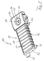
- the contact-connector module 10 represented in figures 1 and 2 is used for installation in the rear side of a mobile telephone apparatus, preferably in a region close to the apparatus's own antenna, which apparatus is represented in merely a token manner in figure 4.
- the contact-connector module 10 is arranged, with its corresponding upper side exposed, in an indentation 41 in the rear side 42 of the casing.
- the indentation 41 is provided with rounded edges for easier introduction of the module 10.
- the contact-connector module 10 possesses a basic body 11 made of an electrically insulating material, the said basic body 11, which will hereinafter be designated as the "insulating body”, having a flat, elongatedly rectangular shape.
- the basic body 11 possesses a main part 12, which is surrounded on three sides by an arrangement 13 consisting of signal contacts and supply-voltage contacts, and a rectangular-shaped, moulded-on extension part 14 which, for example, may also be semicircular and which receives a coaxial antenna-contact arrangement 16 in a recess 15.
- some of the connecting ends, or rather the first connecting ends 17 of the signal and supply-voltage contacts are laid and held flat on the upper side 18 of the main part 12 of the insulating body 11 over, essentially, the entire breadth of the latter (figure 1).
- the other or second connecting ends of the signal and supply-voltage contacts belonging to the arrangement 13 are placed in, and moulded into parallel recesses 23 in such a way that they form contact fingers which are resilient transversely to the longitudinal extent and towards the underside 21.
- a first connecting end 26 of the inner antenna contact 24 of the coaxial antenna-contact arrangement 16 is held, in a resiliently movable manner, in the recess 15 in the extension part 14.
- This first connecting end 26 is formed by nose-like projections 28, 29 arranged on either side of a small, resiliently movable plate.
- a second connecting end 31 of the inner antenna contact 24 is bent over on the underside 21 of the extension part 14 of the insulating body 11.
- a third connecting end 32 belonging to the inner antenna contact 24 rests, in a contact-making manner, against the first connecting end 26 and a fourth connecting end 33, which is in one piece with the said third connecting end, is bent over towards the underside 21 of the insulating body 11.
- the second and fourth connecting ends 31 and 33 respectively, are constructed on the underside 21 as resilient fingers. In the condition in which they are installed in the mobile telephone apparatus 40, the first and third contact ends 26 and 32 of the inner connecting contact 24 make contact with one another.
- the connecting ends 22, 31, 33, which are constructed as resilient fingers, are intended for contact-making with the corresponding contacts on a printed circuit board inside the mobile telephone apparatus when the module 10 is in the installed condition.
- the extension part 14 is masked by a metal cap 34 which surrounds the inner antenna contact 24 and forms the outer antenna contact of the coaxial contact arrangement 16.
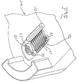
- Figure 5 shows an external connection device in the form of a receiving or supporting device 45 for a mobile telephone 40 which is represented in truncated form in figure 4.
- the supporting device 45 possesses a counterplug-connector 50 for the contact-connector module 10.
- the counterplug-connector 50 is provided with signal contacts 51 in the form of spring fingers which correspond with the flat first connecting ends 17 of the contact-connector module 10.
- the counterplug-connector 50 possesses a coaxial contact 52 which is intended and constructed for contact-making with the projection 28 on the coaxial contact arrangement 16 of the contact-connector module 10.
- the supporting device 45 On one side, the supporting device 45 possesses, alongside the counterplug-connector 50, a strip-like elevation 55 which is provided with lead-in bevels and fits into the indentation represented in figure 4 in the rear side 42 of the mobile telephone 40.
- the contact-connector module 10 is thereby positioned in relation to the counterplug-connector 50.
- the supporting device 45 At either end of the counterplug-connector 50, the supporting device 45 is provided with snap-in hooks 56, 57 which serve, for example, to arrest a cable plug.
- the second connecting ends 22 of the arrangement 13 and the second and fourth connecting ends 31, 33 of the arrangement 16 are constructed on the underside 21 of the insulating body 11 in such a way that they are used, not for solder-less, spring-type contact-making but for soldered connection to the printed circuit board in the mobile telephone apparatus.
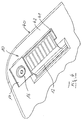
- Figures 3A and 3B shows a step in the manufacture of the two abovementioned variants for the connection to the circuit boards of the mobile telephone apparatus in question.
- the contact arrangements 13 and 16 are placed in an injection mould, not represented, whereupon material belonging to the insulating body 11, which is to be manufactured by injection moulding, is injection moulded around certain regions of the individual signal, coaxial antenna and supply-voltage contacts.
- an intermediate stage of the module 10 is obtained, as shown in figures 3A, 3B.
- the connecting ends of the individual contacts are bent over towards the upper side 18 and underside 21, and optionally shaped, in the form described in connection with figures 1 and 2 or with the above variant.
- the insulating body 11 possesses moulded-on tongues 36 which serve for mechanical fixing inside the rear wall of the casing of the mobile telephone apparatus. Under these circumstances, the said tongues 36 rest against the side of the casing wall under the action of the spring fingers resting on the circuit board. It is obvious that the said flaps 36 are omitted if the module 10 is fastened to the circuit board and held mechanically by means of a soldered connection.
- External connection devices are motor vehicle connecting elements, data plugs which can be connected to a PC or the like, mains apparatuses or the like.
Landscapes
- Engineering & Computer Science (AREA)
- Signal Processing (AREA)
- Coupling Device And Connection With Printed Circuit (AREA)
- Telephone Set Structure (AREA)
- Details Of Connecting Devices For Male And Female Coupling (AREA)
Applications Claiming Priority (2)
| Application Number | Priority Date | Filing Date | Title |
|---|---|---|---|
| DE29915180U DE29915180U1 (de) | 1999-08-30 | 1999-08-30 | Kontaktverbindermodul für Mobiltelefongeräte |
| DE29915180U | 1999-08-30 |
Publications (2)
| Publication Number | Publication Date |
|---|---|
| EP1081807A2 true EP1081807A2 (de) | 2001-03-07 |
| EP1081807A3 EP1081807A3 (de) | 2001-09-26 |
Family
ID=8078201
Family Applications (1)
| Application Number | Title | Priority Date | Filing Date |
|---|---|---|---|
| EP00114356A Withdrawn EP1081807A3 (de) | 1999-08-30 | 2000-07-05 | Kontakttragender Verbindungsmodul für mobile Telefongeräte |
Country Status (4)
| Country | Link |
|---|---|
| US (1) | US6735308B1 (de) |
| EP (1) | EP1081807A3 (de) |
| CA (1) | CA2314568A1 (de) |
| DE (1) | DE29915180U1 (de) |
Cited By (1)
| Publication number | Priority date | Publication date | Assignee | Title |
|---|---|---|---|---|
| EP1677388A1 (de) * | 2004-12-28 | 2006-07-05 | Hosiden Corporation | Koaxial Integrieter Verbinder für Leiterplatte Verbindung |
Families Citing this family (6)
| Publication number | Priority date | Publication date | Assignee | Title |
|---|---|---|---|---|
| DE10164799B4 (de) * | 2001-03-21 | 2006-03-30 | Audioton Kabelwerk Gmbh | Mobiltelefoneinrichtung mit mehradrigen elektrischen Verbindungseinrichtungen |
| DE10113905C2 (de) * | 2001-03-21 | 2003-06-26 | Audioton Kabelwerk Gmbh | Mobiltelefoneinrichtung mit mehradrigen elektrischen Verbindungseinrichtungen |
| US20070124895A1 (en) * | 2005-11-22 | 2007-06-07 | Brown Michael E | Cord management systems |
| US7914310B2 (en) * | 2007-10-29 | 2011-03-29 | Sony Ericsson Mobile Communications Ab | Universal serial bus connector with antenna capabilities |
| CN204216324U (zh) * | 2014-09-02 | 2015-03-18 | 康联精密机电(深圳)有限公司 | 接地良好的高速传输母端连接器 |
| WO2019104521A1 (zh) * | 2017-11-29 | 2019-06-06 | 东莞泰硕电子有限公司 | 一种混装连接器 |
Family Cites Families (10)
| Publication number | Priority date | Publication date | Assignee | Title |
|---|---|---|---|---|
| GB2219159B (en) * | 1988-05-27 | 1993-03-10 | Technophone Ltd | Antenna assembly |
| US5060373A (en) * | 1989-08-22 | 1991-10-29 | The Phoenix Company Of Chicago, Inc. | Methods for making coaxial connectors |
| GB2293283B (en) * | 1994-09-09 | 1999-02-24 | Nokia Mobile Phones Ltd | Combined connector contact |
| DE4440093A1 (de) * | 1994-11-10 | 1996-05-15 | Philips Patentverwaltung | Handtelefon, z.B. Mobiltelefon |
| US5516303A (en) * | 1995-01-11 | 1996-05-14 | The Whitaker Corporation | Floating panel-mounted coaxial connector for use with stripline circuit boards |
| KR100404911B1 (ko) * | 1995-03-16 | 2004-11-03 | 더 휘태커 코포레이션 | 휴대전화기접속시스템 |
| DE19605297A1 (de) * | 1996-02-14 | 1997-08-21 | Swoboda Gmbh Geb | Telefonendgerät und Steckerbuchse für ein Telefonendgerät |
| US5761299A (en) * | 1996-09-24 | 1998-06-02 | Ericsson Inc. | Auxiliary component connector including microphone channel |
| US5961337A (en) * | 1996-11-27 | 1999-10-05 | Norand Corporation | Universal charging and data communication apparatus |
| GB2340333B (en) * | 1998-08-04 | 2002-07-31 | Nokia Mobile Phones Ltd | Radio telephone |
-
1999
- 1999-08-30 DE DE29915180U patent/DE29915180U1/de not_active Expired - Lifetime
-
2000
- 2000-07-05 EP EP00114356A patent/EP1081807A3/de not_active Withdrawn
- 2000-07-20 CA CA002314568A patent/CA2314568A1/en not_active Abandoned
- 2000-08-28 US US09/650,059 patent/US6735308B1/en not_active Expired - Lifetime
Cited By (2)
| Publication number | Priority date | Publication date | Assignee | Title |
|---|---|---|---|---|
| EP1677388A1 (de) * | 2004-12-28 | 2006-07-05 | Hosiden Corporation | Koaxial Integrieter Verbinder für Leiterplatte Verbindung |
| US7198492B2 (en) | 2004-12-28 | 2007-04-03 | Hosiden Corporation | Coaxial connector integrated connector for board connection |
Also Published As
| Publication number | Publication date |
|---|---|
| US6735308B1 (en) | 2004-05-11 |
| EP1081807A3 (de) | 2001-09-26 |
| DE29915180U1 (de) | 2001-01-18 |
| CA2314568A1 (en) | 2001-02-28 |
Similar Documents
| Publication | Publication Date | Title |
|---|---|---|
| JP3429820B2 (ja) | 回路ブレーカ | |
| US6368156B1 (en) | Audio jack conveniently and reliably mounted on a circuit board | |
| KR930024229A (ko) | 고속 보호된 캐비티 백플레인 커넥터 및 그 제조방법 | |
| US11462845B2 (en) | Connector assembly for solderless mounting to a circuit board | |
| US20130295796A1 (en) | Multiple plug connector unit | |
| KR101766198B1 (ko) | 멀티 전원접촉부를 갖는 커넥터 장치 | |
| JPH11233185A (ja) | 低背型表面取付電気コネクタ | |
| KR970054942A (ko) | 표면 장착식 저 프로파일 전기 커넥터 조립체 | |
| US20020175787A1 (en) | Electrical switching element | |
| CA2314568A1 (en) | Contact-connector for mobile telephone apparatuses | |
| US6461168B2 (en) | Plug socket for a display instrument | |
| US7059875B2 (en) | Ground metal fitting and ground structure for jacks of electronic devices | |
| HK1033036A (en) | Contact-connector module for mobile telephone apparatuses | |
| US5993231A (en) | Electric connector | |
| US3737591A (en) | Trap switch with elongated mounting wire for completing continuity circuit | |
| KR20240052039A (ko) | 전기 모터의 전기 모터 권선부와 모터 제어부의 인쇄 회로 기판과의 전기 접촉을 위한 장치 | |
| US7361038B2 (en) | Microswitch connector | |
| CN102148441B (zh) | 连接器用盖以及使用该盖的连接器装置 | |
| JP4834486B2 (ja) | パワー半導体モジュールと端子コネクタとの配置装置 | |
| JP3085988B2 (ja) | 電気的なコネクタ | |
| JPS5812389Y2 (ja) | 音響機器用コネクタ | |
| DK0818072T3 (da) | Anordning til tilslutning af elektriske installationsapparater | |
| JP3219381B2 (ja) | 電気コネクタ | |
| US20060254900A1 (en) | Switching device | |
| JPH06244516A (ja) | 一体成形絶縁部品 |
Legal Events
| Date | Code | Title | Description |
|---|---|---|---|
| PUAI | Public reference made under article 153(3) epc to a published international application that has entered the european phase |
Free format text: ORIGINAL CODE: 0009012 |
|
| AK | Designated contracting states |
Kind code of ref document: A2 Designated state(s): AT BE CH CY DE DK ES FI FR GB GR IE IT LI LU MC NL PT SE |
|
| AX | Request for extension of the european patent |
Free format text: AL;LT;LV;MK;RO;SI |
|
| PUAL | Search report despatched |
Free format text: ORIGINAL CODE: 0009013 |
|
| AK | Designated contracting states |
Kind code of ref document: A3 Designated state(s): AT BE CH CY DE DK ES FI FR GB GR IE IT LI LU MC NL PT SE |
|
| AX | Request for extension of the european patent |
Free format text: AL;LT;LV;MK;RO;SI |
|
| 17P | Request for examination filed |
Effective date: 20011107 |
|
| AKX | Designation fees paid |
Free format text: AT BE CH CY DE DK ES FI FR GB GR IE IT LI LU MC NL PT SE |
|
| 17Q | First examination report despatched |
Effective date: 20041209 |
|
| STAA | Information on the status of an ep patent application or granted ep patent |
Free format text: STATUS: THE APPLICATION IS DEEMED TO BE WITHDRAWN |
|
| 18D | Application deemed to be withdrawn |
Effective date: 20050420 |
|
| REG | Reference to a national code |
Ref country code: HK Ref legal event code: WD Ref document number: 1033036 Country of ref document: HK |