EP1081984A2 - "link-handler" de niveau 2 ainsi que le procédé de connexion de liaison - Google Patents
"link-handler" de niveau 2 ainsi que le procédé de connexion de liaison Download PDFInfo
- Publication number
- EP1081984A2 EP1081984A2 EP00118224A EP00118224A EP1081984A2 EP 1081984 A2 EP1081984 A2 EP 1081984A2 EP 00118224 A EP00118224 A EP 00118224A EP 00118224 A EP00118224 A EP 00118224A EP 1081984 A2 EP1081984 A2 EP 1081984A2
- Authority
- EP
- European Patent Office
- Prior art keywords
- layer
- path
- connection
- link
- user
- Prior art date
- Legal status (The legal status is an assumption and is not a legal conclusion. Google has not performed a legal analysis and makes no representation as to the accuracy of the status listed.)
- Granted
Links
Images


Classifications
-
- H—ELECTRICITY
- H04—ELECTRIC COMMUNICATION TECHNIQUE
- H04Q—SELECTING
- H04Q11/00—Selecting arrangements for multiplex systems
- H04Q11/04—Selecting arrangements for multiplex systems for time-division multiplexing
- H04Q11/0428—Integrated services digital network, i.e. systems for transmission of different types of digitised signals, e.g. speech, data, telecentral, television signals
- H04Q11/0435—Details
-
- H—ELECTRICITY
- H04—ELECTRIC COMMUNICATION TECHNIQUE
- H04L—TRANSMISSION OF DIGITAL INFORMATION, e.g. TELEGRAPHIC COMMUNICATION
- H04L12/00—Data switching networks
- H04L12/54—Store-and-forward switching systems
- H04L12/56—Packet switching systems
- H04L12/5601—Transfer mode dependent, e.g. ATM
- H04L2012/5614—User Network Interface
- H04L2012/5615—Network termination, e.g. NT1, NT2, PBX
-
- H—ELECTRICITY
- H04—ELECTRIC COMMUNICATION TECHNIQUE
- H04L—TRANSMISSION OF DIGITAL INFORMATION, e.g. TELEGRAPHIC COMMUNICATION
- H04L12/00—Data switching networks
- H04L12/54—Store-and-forward switching systems
- H04L12/56—Packet switching systems
- H04L12/5601—Transfer mode dependent, e.g. ATM
- H04L2012/5629—Admission control
- H04L2012/563—Signalling, e.g. protocols, reference model
-
- H—ELECTRICITY
- H04—ELECTRIC COMMUNICATION TECHNIQUE
- H04L—TRANSMISSION OF DIGITAL INFORMATION, e.g. TELEGRAPHIC COMMUNICATION
- H04L12/00—Data switching networks
- H04L12/54—Store-and-forward switching systems
- H04L12/56—Packet switching systems
- H04L12/5601—Transfer mode dependent, e.g. ATM
- H04L2012/5638—Services, e.g. multimedia, GOS, QOS
- H04L2012/5665—Interaction of ATM with other protocols
- H04L2012/5667—IP over ATM
-
- H—ELECTRICITY
- H04—ELECTRIC COMMUNICATION TECHNIQUE
- H04L—TRANSMISSION OF DIGITAL INFORMATION, e.g. TELEGRAPHIC COMMUNICATION
- H04L12/00—Data switching networks
- H04L12/54—Store-and-forward switching systems
- H04L12/56—Packet switching systems
- H04L12/5601—Transfer mode dependent, e.g. ATM
- H04L2012/5687—Security aspects
-
- H—ELECTRICITY
- H04—ELECTRIC COMMUNICATION TECHNIQUE
- H04Q—SELECTING
- H04Q2213/00—Indexing scheme relating to selecting arrangements in general and for multiplex systems
- H04Q2213/13106—Microprocessor, CPU
-
- H—ELECTRICITY
- H04—ELECTRIC COMMUNICATION TECHNIQUE
- H04Q—SELECTING
- H04Q2213/00—Indexing scheme relating to selecting arrangements in general and for multiplex systems
- H04Q2213/13204—Protocols
-
- H—ELECTRICITY
- H04—ELECTRIC COMMUNICATION TECHNIQUE
- H04Q—SELECTING
- H04Q2213/00—Indexing scheme relating to selecting arrangements in general and for multiplex systems
- H04Q2213/1329—Asynchronous transfer mode, ATM
-
- H—ELECTRICITY
- H04—ELECTRIC COMMUNICATION TECHNIQUE
- H04Q—SELECTING
- H04Q2213/00—Indexing scheme relating to selecting arrangements in general and for multiplex systems
- H04Q2213/13296—Packet switching, X.25, frame relay
-
- H—ELECTRICITY
- H04—ELECTRIC COMMUNICATION TECHNIQUE
- H04Q—SELECTING
- H04Q2213/00—Indexing scheme relating to selecting arrangements in general and for multiplex systems
- H04Q2213/13342—Arrangement of switches in the network
-
- H—ELECTRICITY
- H04—ELECTRIC COMMUNICATION TECHNIQUE
- H04Q—SELECTING
- H04Q2213/00—Indexing scheme relating to selecting arrangements in general and for multiplex systems
- H04Q2213/13386—Line concentrator
-
- H—ELECTRICITY
- H04—ELECTRIC COMMUNICATION TECHNIQUE
- H04Q—SELECTING
- H04Q2213/00—Indexing scheme relating to selecting arrangements in general and for multiplex systems
- H04Q2213/13389—LAN, internet
-
- H—ELECTRICITY
- H04—ELECTRIC COMMUNICATION TECHNIQUE
- H04Q—SELECTING
- H04Q2213/00—Indexing scheme relating to selecting arrangements in general and for multiplex systems
- H04Q2213/13399—Virtual channel/circuits
Definitions
- the present invention relates to a layer 2 link handler and layer 2 link path connection method.
- TCP/IP communication represented by LAN or Internet, etc., and it is desired that its communication speed be speeded up.
- This invention concerns a handler and layer 2 link path connection method that handle layer 2 link paths between such layer 3 IP communication and the ATM or other wide-area network of the low-level physical layer.
- SVC switched virtual connection
- PVC permanent virtual connection
- An SVC (switched virtual connection) path is like a path connected in the present telephone network, according to the telephone number of the other party that is specified by the user.
- the ATM path is set according to the user side's specification of the other party's address on the ATM network, and it is set between the user side and the ATM exchange by exchanging, by a protocol known as I.2931, control signals (signalling) for ATM path setting, including a path connection request.
- a PVC (permanent virtual connection) path is a path that is continuously set by a fixed path with the other party. Signalling is not needed to set a path between the user side and the ATM exchange; the path is set in advance by the operator on the ATM network side.
- Figure 26 shows an example of connections using PVC (permanent virtual connection) paths between the user-side device and the device of network service provider (NSP) side.
- PVC permanent virtual connection
- NSP network service provider
- FIG 27 shows the frame composition if IP (Internet protocol) frame data is transmitted along ATM paths such as the aforesaid PVC (permanent virtual connection) paths.
- IP Internet protocol
- PVC permanent virtual connection
- a layer 3 IP frame is encapsulated in a layer 2 PPP (point-to-point protocol) and is broken up by AAL5 (ATM adaptation layer type 5) into ATM cells of the physical layer.
- AAL5 ATM adaptation layer type 5
- a connection by PPP protocol is an example of a connection-oriented layer 2 link, and a 1-to-1 link is set from the user-side device to the device on the network service provider (NSP) side. Only one PPP link can be set on a single PVC (permanent virtual connection) path on the ATM network.
- NSP network service provider
- NSP network service provider
- NSPs network service providers
- NSPs network service providers
- NSP network service provider
- the ATM-side equipment be able to fairly access any network service provider (NSP) as demanded by the user, and it is required that a switching connection be made to any network service provider (NSP) the user wants, even if the user and the network service provider (NSP) are connected by a PVC (permanent virtual connection) path.
- NSP network service provider
- the present invention provides a layer 2 link handler and a path connection method therefor such that it is possible to do traffic line collection by setting multiple layer 2 links on a single physical layer circuit, make network operation efficient, and execute high-speed switching in which multiple layer 2 links are logically separated.
- a layer 2 link handler which is provided in a network-side device, is connected with the user-side device by a permanent virtual connection path, and where said user-side device is made to connect to one among multiple specified connection destinations via a permanent virtual connection path or a switched virtual connection path, the handler comprises a path specification means that specifies one path of the connection request destination from the layer 2 link information that is emitted from the user-side device at the time of a layer 2 link connection request, and a path connection means that causes said permanent virtual connection path connected with user-side device to connect to one path of the connection request destination and form a path between the user-side device and the specified connection destination.
- the path connection means has a distribution means that, by switching on the layer 2 packet level, distributes and transfers packets that arrive from the permanent virtual connection path connected with the user-side device to one path of the connection request destination.
- the path connection means may have a setting means that newly sets one path of the connection request destination specified by the path specification means and connects a path between the user-side device and the specified connection destination.
- the path connection means may have a labelling means which, based on layer 2 link information emitted from the user-side device at the time of a layer 2 link connection request, assigns a label of each layer 2 link of said connection request to a layer 2 packet from the user-side device, and said path connection means has a means that transfers, by label multiplex layer 2 links, the layer 2 packet labelled by the labelling means to the path to said specified connection destination.
- the path connection means recognizes the labels of layer 2 packets that arrive from the permanent virtual connection path with the user-side device and to which labels are assigned for each layer 2 link, and transfers the layer 2 packets to the path to the specified connection destination that corresponds to a given label, and recognizes the labels of labelled layer 2 packets that arrive from the path with the specified connection destination and transfers the layer 2 packets to the permanent virtual connection path to the user-side device that corresponds to a given label.
- the labelling means may have a selection means that, when a label is newly assigned to a layer 2 link, selects an arbitrary available label number and emits a labelled layer 2 packet, and said path connection means handles the link of the labelled layer 2 packet that is assigned the same label number and is sent back from the side of the device that received said labelled layer 2 packet, as a link of the pair of the layer 2 link newly assigned a label.
- the labelling means may have an assigning means that newly selects a label number and assigns it including in the label a marking indicating that it is a transmission from the allocated label number management side, and handles the link of the labelled layer 2 packet sent back from the reception side with the same label number, to which is added a marking indicating a transmission from the label number non-management side, as a link of the pair of the layer 2 link newly assigned a label.
- the labelling means when it newly assigns a label to a layer 2 link, determines the label number by doing a negotiation mutually with the other device side.
- the labelling means when it newly assigns a label to a layer 2 link, assigns a label with a label number directed by operation of a network management operation device.
- the path connection means recognizes the labels of layer 2 packets that arrive from the permanent virtual connection path with the user-side device and to which are assigned labels according to the quality-of-service class of each layer 2 link, and transfers layer 2 packets to the path to the specified connection destination that corresponds to the given label.
- the path connection means may recognize the labels of layer 2 packets that arrive from the permanent virtual connection path with the user-side device and to which are assigned labels according to the connection destination of each layer 2 link, and transfer layer 2 packets to the path to the specified connection destination that corresponds to the given label.
- the path connection means may recognize the labels of layer 2 packets assigned according to the distribution type of service in the IP packet within layer 2 link packets that arrive from the permanent virtual connection path with the user-side device, and transfer layer 2 packets to the path to the specified connection destination that corresponds to the given label.
- the path connection means may have an extracting means that extracts the request connection destination name from layer 2 link information emitted from the user-side device at the time of a layer 2 link connection request and a conversion table that converts from said connection destination name to a connection address, and said path connection means has a means that uses the connection address obtained from said conversion table to cause a path to be connected between the user-side device and the specified connection destination.
- the processing that specifies one path of the connection request destination from layer 2 link information in the path specification means is done under software control by a processor, and the path connection means that connects the permanent virtual connection path of the user-side device to the connection destination after one connection destination path is specified, is constituted by a switching means by hardware.
- the above configuration can be combined appropriately, and is also applied to a layer 2 link handler provided in a user-side network terminating device or a network-side subscriber line concentrator device.
- the layer 2 link path connection method of the present invention provides a layer 2 link handler connected by a permanent virtual connection path with the user-side device, the handler extracting the request connection destination name from layer 2 link information emitted from the user-side device at the time of a layer 2 link connection request, extracting the connection address from the connection destination name by a conversion table, and notifying the user-side device connected by a permanent virtual connection path of said connection address, the user-side device emitting the connection destination address it has been notified of to the network-side device, and based on the connection destination address, the network-side device connecting the user-side device and the connection destination by switching of permanent virtual connection paths or switched virtual connection paths.
- FIG 1 is an explanatory diagram of the layer 2 handler of the present invention.
- Layer 2 handler 1-11 is provided within network-side device (for example, subscriber line concentrator device) 1-10, and by means of the layer 2 handler 1-11, the user-side device connected by a PVC (permanent virtual connection) path is selectively connected to one path of multiple specified connection destinations, such as network service providers (NSPs).
- network-side device for example, subscriber line concentrator device
- PVC permanent virtual connection
- the user-side device is connected to network-side device 1-11 by a PVC (permanent virtual connection) path, and said PVC (permanent virtual connection) path is connected to layer 2 handler 1-11 via ATM switch 1-12, etc.
- PVC permanent virtual connection
- Layer 2 handler 1-11 identifies one path of specified connection destinations based on information for establishing a layer 2 link emitted by the user-side device at the time of initiation of the layer 2 link (PPP, etc.) connection of the user-side device, and a layer 2 packet (PPP packet, etc.) sent from the user-side device to the identified path of the specified connection destination is emitted via ATM switch 1-12, etc.
- PPP layer 2 link
- a layer 2 link on a PVC (permanent virtual connection) path of the ATM network will be explained.
- the layer 1 physical layer is not limited to an ATM network; it may also be a network such as SONET, Ethernet, or frame relay. The same is true also for all the following modes of implementation. In the following, specific implementations of a layer 2 handler to be selectively connected to a specified connection destination will be described.
- FIG. 2 is an explanatory diagram of a mode of implementation of the present invention for PVC (permanent virtual connection) path setting by ATM switching. If between each user-side device #1 to #5 and layer 2 handler 2-11 the connection is made by a PVC (permanent virtual connection) path, and between layer 2 handler 2-11 and the device on the network service provider (NSP-A, NSP-B) side the connection is made by a PVC (permanent virtual connection) path, then layer 2 handler 2-11 connects, by switching at the ATM level (in ATM cell units) the PVC (permanent virtual connection) path from each user-side device #1 to #5 to one specified connection destination path of a device, etc. on the network service provider (NSP-A, NSP-B) side.
- PVC permanent virtual connection
- FIG. 3 is an explanatory diagram of a mode of implementation of the invention for PVC (permanent virtual connection) path setting by layer 2 switching.
- layer 2 handler 3-11 connects, by switching at the layer 2 packet level (in packet units such as PPP packets) the PVC (permanent virtual connection) path from each user-side device #1 to #5 to one specified connection destination path of a device, etc. on the network service provider (NSP-A, NSP-B) side.
- FIG. 4 is an explanatory diagram of a mode of implementation of the invention for SVC (switched virtual connection) path setting by ATM switching.
- PVC permanent virtual connection
- NSP-A, NSP-B network service provider
- SVC switched virtual connection
- layer 2 handler 4-11 specifies one connection destination, such as a network service provider (NSP), from information, etc. for establishing a layer 2 link emitted by the user-side device at the time of initiation of the layer 2 link connection of the user-side device.
- NSP network service provider
- Layer 2 handler 4-11 newly establishes an SVC (switched virtual connection) path to said specified connection destination by a signalling protocol.
- Layer 2 handler 4-11 connects, by switching at the ATM level (in ATM cell units) the PVC (permanent virtual connection) path with the user-side device to an SVC (switched virtual connection) path of one specified connection destination, such as a network service provider (NSP).
- NSP network service provider
- FIG 5 is an explanatory diagram of a mode of implementation of the invention for SVC (switched virtual connection) path setting by layer 2 switching.
- layer 2 handler 5-11 specifies one connection destination, such as a network service provider (NSP), from information, etc. for establishing a layer 2 link emitted by the user-side device at the time of the beginning of the layer 2 link connection of the user-side device.
- NSP network service provider
- Layer 2 handler 5-11 newly establishes an SVC (switched virtual connection) path to said specified connection destination by a signalling protocol.
- Layer 2 handler 5-11 makes a layer 2 connection between the user-side device and one specified connection destination by switching, at the layer 2 packet level, the layer 2 packet (PPP packet, etc.) that arrives from the PVC (permanent virtual connection) path with the user-side device to an SVC (switched virtual connection) path of one specified connection destination, such as a network service provider (NSP).
- PPP packet permanent virtual connection
- SVC switched virtual connection path of one specified connection destination
- NSP network service provider
- Figure 6 is a diagram showing the first mode of implementation of the invention for layer 2 switching by labelling. If between each user-side device #1 to #5 and layer 2 handler 6-11 the connection is made by a PVC (permanent virtual connection) path, and between layer 2 handler 6-11 and the device on the network service provider (NSP-A, NSP-B) side the connection is made by a PVC (permanent virtual connection) path or SVC (switched virtual connection) path, then layer 2 handler 6-11 specifies one connection destination from information, etc. for establishing a layer 2 link emitted by the user-side device at the time of the beginning of the layer 2 link connection of the user-side device.
- PVC permanent virtual connection
- SVC switched virtual connection
- a label to identify each individual layer 2 link is assigned to each layer 2 packet (PPP packet, etc.) that arrives from a PVC (permanent virtual connection) path with the user-side device, the labelled layer 2 packets are switched at the layer 2 packet level, and a layer 2 connection is made between the user-side device and the specified connection destination by multiplexing multiple layer 2 links into a single path of said specified connection destination.
- PPP packet permanent virtual connection
- a PPP packet, etc. which is a layer 2 packet, can set only one link on one physical layer circuit, but by making a conversion to labelled layer 2 packets it becomes possible to set multiple layer 2 links on one physical layer circuit.
- one physical layer circuit such as an ATM path
- the traffic multiplexing effect comes into play, one physical layer circuit such as an ATM network circuit (VC) is effectively used, and the number of them can be reduced.
- VC ATM network circuit
- Figure 7 is a diagram showing the second mode of implementation of the invention for layer 2 switching by labelling. Between each user-side device #1 to #5 and layer 2 handler 7-11 the connection is made by a PVC (permanent virtual connection) path, and between layer 2 handler 7-11 and the device on the network service provider (NSP-A, NSP-B) side the connection is made by a PVC (permanent virtual connection) path or SVC (switched virtual connection) path.
- PVC permanent virtual connection
- SVC switched virtual connection
- Each user-side device #1 to #5 emits to a single PVC (permanent virtual Connection) path a labelled layer 2 packet assigned a label to distinguish individual layer 2 links. That is, layer 2 links that are assigned different labels are multiplexed and set on a single PVC (permanent virtual connection) path between the user-side device and layer 2 handler 7-11.
- PVC permanent virtual Connection
- layer 2 handler 7-11 sets a single connection destination from information, etc. emitted by the user-side device for establishing a layer 2 link.
- Layer 2 handler 7-11 performs a label conversion on the labelled layer 2 packets (PPP packets, etc.) that arrive from the PVC (permanent virtual connection) path with the user-side device, performs switching on the layer 2 packet level to one of the paths of the specified connection destinations to which the labelled layer 2 packet corresponds to said label, and, as in the above mode of implementation shown in Figure 6, connects the user-side device and said connection destination by a multiplexed layer 2 link path between layer 2 handler 7-11 and the specified connection destination.
- PPP packets, etc. the labelled layer 2 packets
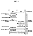
- FIG 8 is an explanatory diagram of the invention's process of establishing layer 2 links.
- Layer 2 handler (L2H) can be constituted so that for complex processing - including the negotiation until one connection destination is specified from the information, etc. emitted by the user-side device (User) for establishing a layer 2 link when the layer 2 link connection of the user-side device (User) is initiated - the processing is done by software, and for switching processing of the PVC (permanent virtual connection) path or SVC (switched virtual connection) path once the one connection destination has been specified, high-speed switching is done by hardware.
- PVC permanent virtual connection
- SVC switched virtual connection
- FIG. 9 is an explanatory diagram of the mode of implementation of the invention for PVC (permanent virtual connection) path setting by an ATM switch.
- layer 2 handler 9-11 is connected via ATM switch 9-12 by a PVC (permanent virtual connection) path with each user-side device, and specifies one connection destination, such as a network service provider, from the information, etc. emitted by the user-side device for establishing a layer 2 link when the user-side device initiates the layer 2 link connection.
- PVC permanent virtual connection
- Layer 2 handler 9-11 indicates the specified connection destination to ATM switch 9-12, and ATM switch 9-12, as shown in (b) of the diagram, performs switching on the ATM level to the indicated specified connection destination and connects the PVC (permanent virtual connection) path from the user-side device to the specified connection destination.
- PVC permanent virtual connection
- composition is such that the connection on the ATM level is made not within layer 2 handler 9-11; until selection of the specified connection destination, processing is done by layer 2 handler 9-11 by giving instructions to ATM switch 9-12, and switching to make the connection to said specified connection destination is done using ATM switch 9-12.
- FIG. 10 is an explanatory diagram of the first mode of implementation of this invention having a conversion table to ATM addresses. As shown in (a) of the diagram, between the user-side device and layer 2 handler 10-11, and between layer 2 handler 10-11 and the device on the network service provider (NSP) side, the connection is made by a PVC (permanent virtual connection) path via ATM switch 10-12.
- PVC permanent virtual connection
- layer 2 handler 10-11 has a conversion table from specified connection destination names, such as network service provider (NSP) names, to the ATM address of the PVC (permanent virtual connection) path that corresponds to a given specified connection destination.
- NSP network service provider
- layer 2 handler 10-11 uses said conversion table to obtain the ATM address that corresponds to said connection destination, and makes the ATM connection based on said ATM addresses.
- NSP network service provider
- a connection can be selectively made to a network service provider or other specified connection destination connected by a PVC (permanent virtual connection) path, even if the user-side device is not aware of the ATM address of the specified connection destination.
- PVC permanent virtual connection
- FIG. 11 is an explanatory diagram of the second mode of implementation of this invention having a conversion table to ATM addresses.
- a connection is made by a PVC (permanent virtual connection) path via ATM switch 11-12, and between layer 2 handler 11-11 and the device on the network service provider (NSP) side, a connection is made by an SVC (switched virtual connection) path via ATM switch 11-12.
- PVC permanent virtual connection
- SVC switched virtual connection
- layer 2 handler 11-11 has a conversion table from specified connection destination names, such as network service provider (NSP) names, to the ATM address of the SVC (switched virtual connection) path that corresponds to a given specified connection destination.
- NSP network service provider
- layer 2 handler 11-11 uses said conversion table to obtain the ATM address that corresponds to said connection destination, and notifies the user-side device of said ATM address.
- NSP network service provider
- the user-side device emits the ATM address it has been notified of to ATM switch 11-12, and based on said ATM address, ATM switch 11-12 sets an SVC (switched virtual connection) path to the network service provider (NSP) or other specified connection destination, as shown in (c) of the diagram.
- SVC switched virtual connection
- a connection can be selectively made to a network service provider or other specified connection destination via ATM switch 11-12, which is connected by a PVC (permanent virtual connection) path, even if the user-side device is not aware of the ATM address of the specified connection destination.
- PVC permanent virtual connection
- Figure 12 is an explanatory diagram of the present invention's user-side network terminating device having a labelling function.
- user-side network terminating device optical network unit (ONU), etc.
- ONU optical network unit
- labels that identify individual layer 2 links are assigned to layer 2 packets (PPP packets, etc.) that arrive from PVC (permanent virtual connection) paths of the user-side device, the labelled layer 2 packets are distributed to network-side PVC (permanent virtual connection) paths, multiple layer 2 links are multiplexed to network-side PVC (permanent virtual connection) paths, and connections are made between the user side and the network side.
- PPP packets permanent virtual connection
- the link of only one PPP or other protocol packet which is a layer 2 packet, can be put on a single physical layer circuit. But by converting layer 2 packets to labelled layer 2 packets, multiple layer 2 links can be put on a single physical circuit.
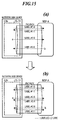
- Figure 13 is a diagram showing a mode of implementation of this invention for layer 2 switching for PVC (permanent virtual connection) and SVC (switched virtual connection) paths.
- PVC permanent virtual connection
- SVC switched virtual connection
- layer 2 handler 13-11 If the relevant specified connection destination is connected by a PVC (permanent virtual connection) path, layer 2 handler 13-11 emits a layer 2 packet to said PVC (permanent virtual connection) path, but if the relevant specified connection destination is not connected by a PVC (permanent virtual connection) path, it newly sets a path to said specified connection destination using an SVC (switched virtual connection) path.
- PVC permanent virtual connection
- PVC permanent virtual connection
- SVC switched virtual connection
- Figure 14 is an explanatory diagram of a mode of implementation of the present invention that assigns arbitrary labels.
- the device on the side that newly assigns labels to layer 2 links and emits labelled packets selects arbitrary available label numbers and assigns to layer 2 packets, and the device that receives said labelled layer 2 packets assigns to the return-direction link corresponding to a received link a label of the same number as the number of said assigned label.
- layer 2 handler 14-11 within network-side device 14-10 extends a new link 'a' when a layer 2 link to which label #1 has been assigned is set between it and a network service provider (NSP-A), then layer 2 handler 14-11 selects and allocates an arbitrary label #2 that is not currently being used and transmits a layer 2 packet to which said label #2 is assigned.
- NSP-A network service provider
- the network service provider that receives layer 2 packet bearing label #2 assigns the same label #2 as the received layer 2 packet to the link to layer 2 handler 14-11 corresponding to the link on which the layer 2 packet bearing label #2 was received.
- NSP-A layer 2 packet bearing label #2
- Figure 15 is an explanatory diagram of a mode of implementation of the invention that does labelling to prevent collisions. If the same label number is assigned to a layer 2 link so as to form the pair described above, then a different marking is made on each label, as between the side that first selects an arbitrary available label number and emits a labelled layer 2 packet, and the side that assigns the same label number to the link of the pair on the side that receives said labelled layer 2 packet and emits it.
- layer 2 handler 15-11 sets a new link 'a' when a bi-directional layer 2 link to which label #1-0 and label #1-1 have been assigned is set between it and a network service provider (NSP-A), then layer 2 handler 15-11 selects and allocates an arbitrary label #2-0 that is not currently being used and transmits a layer 2 packet to which said label #2-0 is assigned.
- NSP-A network service provider
- a labelled layer 2 packet with a label number assigned, for example, the marking "0 is transmitted, and the other device that receives the layer 2 packet to which this marking is assigned puts, for example, the marking "1 on the label number of the layer 2 packet to be emitted to the link of the pair.
- layer 2 handler 15-11 is able to distinguish by label number #2-0 assigned as link 'b' that the device on the network service provider (NSP-A) side newly tries to set, and while being a simple labelling system, label number collisions can be avoided even if both devices do label management independently.
- NSP-A network service provider
- Figure 16 is an explanatory diagram of a mode of implementation of the invention that does labelling by negotiation.
- layer 2 handler 6-11 sets a new link when a layer 2 link to which label #1 is assigned is set between it and a network service provider (NSP-A)
- NSP-A network service provider
- a negotiation takes place mutually with the network service provider (NSP-A) concerning label numbers
- an arbitrary label #2 that is not currently being used is selected and decided upon, and a bi-directional link of label #2 is set.
- Negotiation makes it possible to assign labels without any collisions.
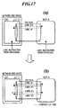
- Figure 17 is an explanatory diagram of a mode of implementation of the invention that does labelling by network operation. As shown in (a) of the diagram, if a new link is set between layer 2 handler 17-11 and a network service provider (NSP-A), then the label to assign is prescribed by operation of the network's management operation device.
- NSP-A network service provider
- Layer 2 handler 17-11 and the network service provider (NSP-A) can do labelling without collisions by assigning to the layer 2 links labels prescribed by operation of the network management operation device.
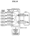
- Figure 18 is an explanatory diagram of a mode of implementation of the invention that does labelling according to quality-of-service (QoS) class.
- the user-side device or user-side network terminating device (ONU) assigns labels classified by the requested quality of service (QoS) and emits layer 2 packets, and based on the labels, layer 2 handler 18-11 distributes them to PVC (permanent virtual connection) paths classified by each QoS.
- PVC permanent virtual connection
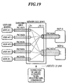
- Figure 19 is an explanatory diagram of a mode of implementation of the invention that does labelling according to connection destination.
- the user-side device or user-side network terminating device (ONU) assigns labels classified by the connection destination and emits layer 2 packets, and based on the labels, layer 2 handler 19-11 distributes them to PVC (permanent virtual connection) paths classified by each connection destination.
- PVC permanent virtual connection
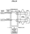
- Figure 20 is an explanatory diagram of a layer 2 handler of the invention that does labelling according to distribution type of service (ToS). Based on the value of the distribution type of service (ToS) field in the IP packet within a layer 2 packet, layer 2 handler 20-11 assigns QoS-classified labels to layer 2 packets according to the value of the ToS field, and emits them.
- ToS distribution type of service
- information on the type of distribution route requested from the user-side device determines, in accordance with it, the selection of the distribution route, such as whether to use a route whose delay is as small as possible, whether to use a route whose throughput is as large as possible, or whether to use a route whose reliability is as high as possible.
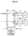
- Figure 21 is an explanatory diagram of a user-side network terminating device (ONU) of this invention that does labelling according to distribution type of service. Based on the value of the distribution type of service (ToS) field in the IP packet within a layer 2 packet, user-side network terminating device (ONU) assigns "ToS" classified labels to layer 2 packets according to the value of the ToS field, and emits them.
- ToS distribution type of service
- Figure 22 shows a mode of implementation in which a layer 2 handler of this invention if provided within a subscriber line concentrator device (optical line terminator, OLT). It has layer 2 handier 22-11 and ATM switch 22-12 within subscriber line concentrator device (OLT) 22-10, and between the user-side device and layer 2 handler 22-11 a PVC (permanent virtual connection) path is extended via ATM switch 22-12.
- OLT optical line terminator
- layer 2 handler 22-11 and network service provider-side device (NSP-X) and network service provider-side device (NSP-Y) a PVC (permanent virtual connection) path is extended via ATM switch 22-12.
- NSP-X network service provider-side device
- NSP-Y network service provider-side device
- An example of the composition of layer 2 handler 22-11 is described as follows.
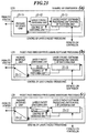
- Figure 23 is an explanatory diagram of an example of the composition of the layer 2 handler of the present invention.
- (a) shows an example of the composition
- (b) shows the pass-through route of a layer 2 packet during software processing
- (c) shows the pass-through route of a layer 2 packet during hardware processing.
- Package interface unit 23-11 receives cells from the ATM switch and assembles PPP or other layer 2 packets. Also, layer 2 packets are broken up into ATM cells and passed to the ATM switch.
- Layer 2 packet switching unit 23-12 is hardware that performs switching and labelling of PPP and other layer 2 packets; among the layer 2 packets, for packets that require negotiation, processing is passed to layer 2 packet software processing unit 23-13 as shown in (b) of the diagram, and for packets with a link whose connection destination is specified, switching and labelling is done and the packets are emitted to the ATM switch via package interface unit 23-11 as shown in (c) of the diagram.
- Layer 2 packet software processing unit 23-13 receives packets that require negotiations and performs negotiation. In this process, the desired connection destination is specified from the user side, and control of layer 2 packet switching unit 23-12 is carried out.
- FIG 24 is an explanatory diagram of the operations of the layer 2 handler of this invention.
- User A initiates a PPP layer 2 protocol transmission sequence.
- an LCP_ConfReq packet is emitted in PPP-over-ATM format on the PVC to the layer 2 handler (24-1).
- This packet is received by the layer 2 handler (L2H), and at the layer 2 handler, the PPP packet is taken out by the ATM interface, it goes through the layer 2 switch engine, and it is received by the layer 2 controller. At the layer 2 controller, software processing of this packet is initiated, and an LCP_ConfAck packet is sent back to the user side (24-2).
- the layer 2 handling device emits a CHAP_Challenge packet (24-3).
- user A emits his user ID and password (24-4).
- user A emits his own user ID in the format "aaa@nspx".
- the layer 2 controller specifies the network service provider (NSP) name "nspx" to be connected with this user.
- the layer 2 handler Using the PVC (permanent virtual connection) path to the network service provider (NSF) name "nspx" to be connected, the layer 2 handler emits to network service provider "nspx" an LCP_ConfReq packet for connection setting in labelled PPP-over-ATM format.
- NSF network service provider
- the layer 2 controller obtains from the label management table a label number, here [2], that is not being used in the PVC (permanent virtual connection) path to network service provider (NSP) "nspx". Then to this label number it emits as the label of [2-0], including marking [0] meaning that it is an emission from the label management side (24-5).
- NSP network service provider
- the LCP_ConfReq of the PPP packet of label [2-0] is received, label [2-1] of the transmission packet that corresponds to received label [2-0] is added, and the LCP_ConfAck of the PPP packet is returned (24-6).
- label [2-1] the label number is 2, and marking [1], which means that it is an emission from the label number non-management side, is added.
- multiple PPP packets can be multiplexed on a single PVC (permanent virtual connection) path by assigning labels to PPP packets between the layer 3 handler and the network service provider (NSP). And by adding a marking that distinguishes whether it is from the label number management side or non-management side, label collisions are avoided even if the management of label numbers is done separately by each device.
- PVC permanent virtual connection
- the layer 2 handler emits user A's ID and password to network service provider (NSP) "nspx" (24-7). And the layer 2 controller of the layer 2 handler sets the following hardware operation with respect to the layer 2 switch engine unit.
- NSP network service provider
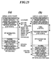
- Figure 25 shows an example of the format of a labelled layer 2 packet of this invention.
- (a) shows the usual PPP-over-ATM packet format
- (b) shows the labelled PPP-over-ATM packet format.
- the assigned label is stored in the region of (b) indicated by "Label”.
- the present invention makes it possible to select and connect one of specified connection destinations, even if the user-side device is connected by a permanent virtual connection path, by specifying the path of one of the connection request destinations from layer 2 link information emitted from the user-side device connected by a permanent virtual path when a layer 2 link connection request is made, and connecting the permanent virtual connection path of the user-side device to the path of one of the connection request destinations.
- switching can be done that is logically separated by the assigned labels, without referring to the IP address in the layer 3 IP header, etc., even if user devices of multiple companies having the same private address are accommodated in layer 2.
- the high-speed switching by hardware can be done by doing the switching by the assigned labels of layer 2 packets, without referring to the IP address in the layer 3 IP header, etc.
- NSP network service provider
Landscapes
- Engineering & Computer Science (AREA)
- Computer Networks & Wireless Communication (AREA)
- Data Exchanges In Wide-Area Networks (AREA)
Applications Claiming Priority (2)
| Application Number | Priority Date | Filing Date | Title |
|---|---|---|---|
| JP24962799A JP4267777B2 (ja) | 1999-09-03 | 1999-09-03 | レイヤ2リンクのハンドリング装置 |
| JP24962799 | 1999-09-03 |
Publications (3)
| Publication Number | Publication Date |
|---|---|
| EP1081984A2 true EP1081984A2 (fr) | 2001-03-07 |
| EP1081984A3 EP1081984A3 (fr) | 2005-12-07 |
| EP1081984B1 EP1081984B1 (fr) | 2008-01-16 |
Family
ID=17195849
Family Applications (1)
| Application Number | Title | Priority Date | Filing Date |
|---|---|---|---|
| EP00118224A Expired - Lifetime EP1081984B1 (fr) | 1999-09-03 | 2000-09-01 | "Link-handler" de couche 2 ainsi que le procédé de connexion de liaison correspondant |
Country Status (4)
| Country | Link |
|---|---|
| US (1) | US7424005B1 (fr) |
| EP (1) | EP1081984B1 (fr) |
| JP (1) | JP4267777B2 (fr) |
| DE (1) | DE60037782T2 (fr) |
Families Citing this family (3)
| Publication number | Priority date | Publication date | Assignee | Title |
|---|---|---|---|---|
| JP2002368788A (ja) * | 2001-06-05 | 2002-12-20 | Japan Telecom Holdings Co Ltd | 経路制御ドメインの相互接続方法および相互接続装置 |
| US7535910B2 (en) * | 2002-12-13 | 2009-05-19 | At&T Intellectual Property I, L.P. | Method and system for obtaining a permanent virtual circuit map |
| EP3756286A4 (fr) * | 2018-02-22 | 2021-12-22 | Eos Defense Systems Usa, Inc. | Liaison sans fil hybride utilisant une communication optique en espace libre, une communication radiofréquence et une commutation intelligente de trame et de paquet |
Family Cites Families (12)
| Publication number | Priority date | Publication date | Assignee | Title |
|---|---|---|---|---|
| US6016319A (en) * | 1995-10-31 | 2000-01-18 | Lucent Technologies, Inc. | Communications system for transmission of datagram packets over connection-oriented networks |
| JPH1098524A (ja) * | 1996-09-20 | 1998-04-14 | Nippon Telegr & Teleph Corp <Ntt> | 分散型ネットワーク |
| CA2217275C (fr) * | 1997-10-03 | 2005-08-16 | Newbridge Networks Corporation | Partitions d'interreseautage multiples dans un dispositif d'interreseautage |
| WO1999018761A2 (fr) | 1997-10-06 | 1999-04-15 | Jens Kurrat | Dispositif de transmission sans fil de donnees numeriques, notamment de donnees audio |
| JP2982784B2 (ja) * | 1998-03-31 | 1999-11-29 | 日本電気株式会社 | Atm交換機管理システム |
| FI110987B (fi) * | 1998-03-31 | 2003-04-30 | Nokia Corp | Menetelmä tiedonsiirtovirtausten kytkemiseksi |
| KR100513030B1 (ko) * | 1998-04-08 | 2005-11-21 | 삼성전자주식회사 | 비동기 전송망의 교환가상회선을 이용한 온라인 전용회선관리방법 |
| US6473430B2 (en) * | 1998-06-03 | 2002-10-29 | Samsung Electronics Co., Ltd. | Systems and methods for connecting frame relay devices via an ATM network using a frame relay proxy signaling agent |
| US6618377B1 (en) * | 1999-03-30 | 2003-09-09 | Cisco Technology, Inc. | Flexible scheduling of network devices within redundant aggregate configurations |
| US7012892B1 (en) * | 1999-04-16 | 2006-03-14 | Alcatel Canada Inc. | Method and apparatus for supporting connection type partitioning in a communications network |
| US6714544B1 (en) * | 1999-07-08 | 2004-03-30 | Alcatel Canada Inc. | Method and apparatus for proxied signalling of an end to end connection across a connection oriented network |
| US6738354B1 (en) * | 2000-02-18 | 2004-05-18 | Nortel Networks Limited | Label selection for end-to-end label-switched traffic through a communications network |
-
1999
- 1999-09-03 JP JP24962799A patent/JP4267777B2/ja not_active Expired - Fee Related
-
2000
- 2000-08-30 US US09/651,988 patent/US7424005B1/en not_active Expired - Fee Related
- 2000-09-01 EP EP00118224A patent/EP1081984B1/fr not_active Expired - Lifetime
- 2000-09-01 DE DE60037782T patent/DE60037782T2/de not_active Expired - Lifetime
Also Published As
| Publication number | Publication date |
|---|---|
| JP2001077824A (ja) | 2001-03-23 |
| EP1081984B1 (fr) | 2008-01-16 |
| US7424005B1 (en) | 2008-09-09 |
| EP1081984A3 (fr) | 2005-12-07 |
| DE60037782D1 (de) | 2008-03-06 |
| JP4267777B2 (ja) | 2009-05-27 |
| DE60037782T2 (de) | 2009-01-15 |
Similar Documents
| Publication | Publication Date | Title |
|---|---|---|
| US6424662B1 (en) | Router apparatus using ATM switch | |
| US6600741B1 (en) | Large combined broadband and narrowband switch | |
| US7809015B1 (en) | Bundling ATM and POS data in a single optical channel | |
| US5809022A (en) | Method and apparatus for converting synchronous narrowband signals into broadband asynchronous transfer mode signals | |
| US5548589A (en) | Connectionless communication system and method of connectionless communication | |
| EP1098479B1 (fr) | Système de commutation de packets avec commutateurs à autonomie d'acheminement | |
| JPH04225649A (ja) | パケット交換システム | |
| EP0471379A2 (fr) | Système et méthode de commutation de paquets avec commutateur à autoroutage | |
| US5740156A (en) | Packet switching system having self-routing switches | |
| JP3930035B2 (ja) | データ転送装置およびデータ転送システム | |
| EP1237309B1 (fr) | Système de communication par fibres optiques | |
| EP0797373B1 (fr) | Procédé et dispositif dans un réseau intégré de télécommunication pour convertir des signaux à bande étroite en signaux à bande large et transmis en mode de transfert asynchrone | |
| US6005867A (en) | Time-division channel arrangement | |
| JP2001086138A (ja) | 回路及びパケット・データ送信統合用の通信チャンネル同期マイクロセル・システム | |
| EP1081984B1 (fr) | "Link-handler" de couche 2 ainsi que le procédé de connexion de liaison correspondant | |
| EP1718000A1 (fr) | Reseau de communication par paquets, serveur de controle d'itineraire, procede de controle d'itineraire, dispositif de transmission par paquets, serveur de controle d'admission, procede de reglage d'itineraire | |
| CN1338170A (zh) | 提供机间中继的方法与装置 | |
| EP1145588B1 (fr) | Mecanisme et procede d'affectation dynamique de connexions atm entre des centraux | |
| US20050213599A1 (en) | Distributed LAN bridging system and process | |
| JP2001507914A (ja) | 異種の伝送特性を使用する通信ネットワーク | |
| US7058062B2 (en) | Packet switching system having self-routing switches | |
| JP3349725B2 (ja) | Lan間接続制御方法 | |
| KR20020069578A (ko) | 인터넷 프로토콜을 사용하는 네트워크에서 서비스 품질우선순위를 지원하는 전송 시스템 및 방법 | |
| Quinquis et al. | Data services and lans interconnection using atm technique | |
| JPH06268673A (ja) | Atm通信方式 |
Legal Events
| Date | Code | Title | Description |
|---|---|---|---|
| PUAI | Public reference made under article 153(3) epc to a published international application that has entered the european phase |
Free format text: ORIGINAL CODE: 0009012 |
|
| AK | Designated contracting states |
Kind code of ref document: A2 Designated state(s): AT BE CH CY DE DK ES FI FR GB GR IE IT LI LU MC NL PT SE |
|
| AX | Request for extension of the european patent |
Free format text: AL;LT;LV;MK;RO;SI |
|
| RIC1 | Information provided on ipc code assigned before grant |
Ipc: 7H 04L 12/56 A |
|
| PUAL | Search report despatched |
Free format text: ORIGINAL CODE: 0009013 |
|
| AK | Designated contracting states |
Kind code of ref document: A3 Designated state(s): AT BE CH CY DE DK ES FI FR GB GR IE IT LI LU MC NL PT SE |
|
| AX | Request for extension of the european patent |
Extension state: AL LT LV MK RO SI |
|
| 17P | Request for examination filed |
Effective date: 20060208 |
|
| AKX | Designation fees paid |
Designated state(s): DE FR GB |
|
| 17Q | First examination report despatched |
Effective date: 20060302 |
|
| RTI1 | Title (correction) |
Free format text: LAYER 2 LINK HANDLER AND PATH CONNECTION METHOD THEREFOR |
|
| GRAP | Despatch of communication of intention to grant a patent |
Free format text: ORIGINAL CODE: EPIDOSNIGR1 |
|
| GRAS | Grant fee paid |
Free format text: ORIGINAL CODE: EPIDOSNIGR3 |
|
| GRAA | (expected) grant |
Free format text: ORIGINAL CODE: 0009210 |
|
| AK | Designated contracting states |
Kind code of ref document: B1 Designated state(s): DE FR GB |
|
| REG | Reference to a national code |
Ref country code: GB Ref legal event code: FG4D |
|
| REF | Corresponds to: |
Ref document number: 60037782 Country of ref document: DE Date of ref document: 20080306 Kind code of ref document: P |
|
| ET | Fr: translation filed | ||
| PLBE | No opposition filed within time limit |
Free format text: ORIGINAL CODE: 0009261 |
|
| STAA | Information on the status of an ep patent application or granted ep patent |
Free format text: STATUS: NO OPPOSITION FILED WITHIN TIME LIMIT |
|
| 26N | No opposition filed |
Effective date: 20081017 |
|
| PGFP | Annual fee paid to national office [announced via postgrant information from national office to epo] |
Ref country code: GB Payment date: 20090826 Year of fee payment: 10 |
|
| PGFP | Annual fee paid to national office [announced via postgrant information from national office to epo] |
Ref country code: DE Payment date: 20090827 Year of fee payment: 10 |
|
| PGFP | Annual fee paid to national office [announced via postgrant information from national office to epo] |
Ref country code: FR Payment date: 20091012 Year of fee payment: 10 |
|
| GBPC | Gb: european patent ceased through non-payment of renewal fee |
Effective date: 20100901 |
|
| REG | Reference to a national code |
Ref country code: FR Ref legal event code: ST Effective date: 20110531 |
|
| REG | Reference to a national code |
Ref country code: DE Ref legal event code: R119 Ref document number: 60037782 Country of ref document: DE Effective date: 20110401 |
|
| PG25 | Lapsed in a contracting state [announced via postgrant information from national office to epo] |
Ref country code: DE Free format text: LAPSE BECAUSE OF NON-PAYMENT OF DUE FEES Effective date: 20110401 Ref country code: FR Free format text: LAPSE BECAUSE OF NON-PAYMENT OF DUE FEES Effective date: 20100930 |
|
| PG25 | Lapsed in a contracting state [announced via postgrant information from national office to epo] |
Ref country code: GB Free format text: LAPSE BECAUSE OF NON-PAYMENT OF DUE FEES Effective date: 20100901 |