EP1081993A2 - Socle pour boitier dont les broches sont rangées en grille - Google Patents
Socle pour boitier dont les broches sont rangées en grille Download PDFInfo
- Publication number
- EP1081993A2 EP1081993A2 EP00114571A EP00114571A EP1081993A2 EP 1081993 A2 EP1081993 A2 EP 1081993A2 EP 00114571 A EP00114571 A EP 00114571A EP 00114571 A EP00114571 A EP 00114571A EP 1081993 A2 EP1081993 A2 EP 1081993A2
- Authority
- EP
- European Patent Office
- Prior art keywords
- slide plate
- actuator
- slide
- socket
- base housing
- Prior art date
- Legal status (The legal status is an assumption and is not a legal conclusion. Google has not performed a legal analysis and makes no representation as to the accuracy of the status listed.)
- Withdrawn
Links
- 230000000295 complement effect Effects 0.000 claims description 6
- 230000037431 insertion Effects 0.000 claims description 6
- 238000003780 insertion Methods 0.000 claims description 6
- 230000007246 mechanism Effects 0.000 abstract description 10
- 239000004065 semiconductor Substances 0.000 description 2
- 239000003989 dielectric material Substances 0.000 description 1
Images


Classifications
-
- H—ELECTRICITY
- H05—ELECTRIC TECHNIQUES NOT OTHERWISE PROVIDED FOR
- H05K—PRINTED CIRCUITS; CASINGS OR CONSTRUCTIONAL DETAILS OF ELECTRIC APPARATUS; MANUFACTURE OF ASSEMBLAGES OF ELECTRICAL COMPONENTS
- H05K7/00—Constructional details common to different types of electric apparatus
- H05K7/02—Arrangements of circuit components or wiring on supporting structure
- H05K7/10—Plug-in assemblages of components, e.g. IC sockets
- H05K7/1007—Plug-in assemblages of components, e.g. IC sockets with means for increasing contact pressure at the end of engagement of coupling parts
Definitions
- This invention generally relates to a socket for a pin grid array package and, particularly, to an improved actuating mechanism for the socket.
- Sockets are provided for a pin grid array (PGA) package such as a semi-conductor integrated circuit package in which lead pins are provided in a grid array.
- a typical socket includes a planar base housing provided with a plurality of terminals which can be electrically engaged with the lead pins of the PGA package.
- a planar slide member or plate is disposed on an upper side of the base housing and is provided with a plurality of through-holes in a grid array and through which the lead pins can be inserted.
- a cover member may be provided on top of the slide plate, and through-holes also are provided in the cover member. Examples of such sockets are shown in Japanese Patent Laid-Open Publication No. Hei 7-142134 and Japanese Utility Model Registration No. 253644.
- the slide plate for the socket described above allows the lead pins to be inserted into the socket with a zero insertion force when the slide plate is in a first or open position.
- the plate is slidably moved relative to the base housing to a second or engagement position whereat the lead pins are brought into electrical connection with the terminals mounted on the base housing.
- some form of actuating mechanism is provided, operatively associated between the base housing and the slide plate, for moving the slide plate between its first and second positions.
- actuating mechanism is an eccentric shaft which is basically in the form of a screw member which is operated by an appropriate tool, such as a screwdriver.
- the screw member is axially fixed to the base housing but is rotatable relative thereto.
- the screw member has an eccentric portion engageable with the slide plate. Therefore, upon rotation of the screw member, the eccentric portion thereof moves the slide plate relative to the base housing between its first or open position and its second or engagement position.
- lever or operating handle rotatably mounted to the base housing.
- the lever or handle has an eccentric or cam shaft for engaging the slide plate and moving the slide plate relative to the base housing.
- the present invention is directed to solving these problems by providing a low profile actuating mechanism which is simple to operate and requires no tools.
- An object, therefore, of the invention is to provide a new and improved socket for a pin grid array (PGA) package having a plurality of lead pins in a grid array.
- PGA pin grid array
- Another object of the invention is to provide an improved operating or actuating mechanism for such sockets.
- the socket includes a base housing and a plurality of terminals mounted on the base housing in a grid array corresponding to the grid array of the lead pins of the PGA package.
- a slide plate is mounted on the base housing and includes a plurality of through-holes arranged in a grid array for receiving therethrough the lead pins of the PGA package.
- the slide plate is slidably movable relative to the base housing in a given direction to drive the lead pins of the PGA package into engagement with the terminals on the base housing.
- a slide actuator is mounted on the base housing for sliding movement relative thereto in a direction generally transversely of the given direction of sliding movement of the slide plate.
- Complementary interengaging cam structure is provided between the slide plate and the slide actuator for slidably moving the slide plate relative to the base housing in response to sliding movement of the actuator relative to the housing.
- the complementary interengaging cam structure includes a cam slot on one of the slide plate or slide actuator for receiving a cam follower on the other of the slide plate or slide actuator.
- the cam slot extends oblique to the given direction of sliding movement of the slide plate.
- the cam slot is on the slide actuator and the cam follower comprises a pin on the slide plate inserted into the cam slot.
- the cam slot includes a land area at least at one end thereof and extending generally perpendicular to the given direction of sliding movement of the slide plate. This land area prevents the cam follower from migrating along the cam slot once the slide plate is in its intended position.
- one of the land areas is provided at both opposite ends of the cam slot.
- Another feature of the invention is the provision of complementary interengaging detent structure between the slide actuator and the base housing to hold the actuator in at least one of its open or closed positions.
- the detent structure is provided for holding the actuator in either of its open or closed positions.
- the detent structure also provides a tactile and audible indication of the actuator reaching either of its positions.
- the socket includes three major components, all of which are molded of dielectric material such as plastic or the like, and a plurality of conductive terminals.
- the three major components include a base housing, generally designated 10; a slide plate, generally designated 20; and a slide actuator, generally designated 30.
- Slide plate 20 is slidably mounted on base housing 10 for movement relative thereto in the direction of double-headed arrow "A.”
- Slide actuator 30 is slidably mounted on the base housing for sliding movement relative thereto generally in the direction of double-headed arrow "B.” Sliding movement of slide actuator 30, therefore, is generally transversely of the sliding movement of slide plate 20.
- base housing 10 is generally rectangular and is thin or low profile and includes opposite sides 11 having a plurality of latch projections 12.
- the housing includes a first recessed area 13 and a second recessed area 14.
- the first recessed area includes a plurality of terminal-receiving passages 15 in a grid array corresponding to the grid array of the lead pins of the PGA package.
- Second recessed area 14 slidably receives slide actuator 30 to define its movement in the direction of double-headed arrow "B.”
- Slide plate 20 of socket 1 also has a low profile and is rectangular like base housing 10.
- the side plate has side walls 21 which overlap sides 11 of the base housing and include inwardly directed latch projections 22 (see Fig. 5) for latchingly engaging latch projections 12 at sides 11 of base housing 10.
- Latch projections 11 and 22 on the base housing and slide plate, respectively, are elongated in the direction of double-headed arrow "A" to allow the slide plate to reciprocally move in that direction, while side walls 21 of the slide plate prevent the plate from moving transversely of that direction.
- slide plate 20 further includes a plurality of through holes 23 arranged in a grid array generally corresponding to the grid array of terminal-receiving passages 15 in the base housing and corresponding to the grid array of the lead pins of the PGA package.
- the slide plate includes a recessed area 24 that extends substantially the entire width of base housing 10 along one edge thereof for accommodating an actuating button of slide actuator 30, as described hereinafter.
- a cam follower pin 25 projects downwardly from the slide plate adjacent the recessed area, and a pair of upwardly facing detent projections 26 and 27 are formed at opposite ends of the recessed area, all for purposes to be described hereinafter.
- Slide actuator 30 of socket 1 is molded generally in the form of a rectangular plate-like member which seats in recessed area 14 of base housing 10 for reciprocal movement therewithin in the direction of double-headed arrow "B."
- the slide actuator is about one half the length of recessed area 24 in order to permit substantial movement of the actuator within recessed area 24.
- An actuating button 31 extends from the slide actuator, and the top surface of the button is serrated or undulated to facilitate engagement thereof by an operator's finger.
- the button also includes raised end sections 31a that extend upwardly from slide actuator 30 provide additional; surfaces that can be enjoyed by the operators finger.
- the slide actuator has an elongated cam slot 32 for receiving cam follower pin 25 of slide plate 20.
- a pair of downwardly facing detent projections 36 and 37 are formed on the underside of actuating button 31 for engaging upwardly facing flexible detent projections 26 and 27, respectively, at opposite ends of recess area 24 of slide plate 20.
- Figure 2 shows slide actuator 30 and actuating button 31 in its open position, with slide plate 20 in a position for receiving the lead pins of the PGA package with zero insertion force.
- Figure 2 shows actuating button 31 having moved the slide actuator in the direction of arrow "C" which is effective to move slide plate 20 in the direction of arrow "D” to its engagement position.
- downwardly facing flexible detent projection 36 of the slide actuator interengages with upwardly facing flexible detent projection 26 on slide plate 20.
- downwardly facing detent projection 37 interengages with upwardly facing detent projection 27 of the slide plate.
- the detent projections hold the slide actuator in its two limit positions.
- the detent projections are rounded and provide both a tactical as well as an audible or "snapping" indication that the slide actuator has reached either of its two limit positions.
- FIG 4 shows somewhat schematically the configuration of slide actuator 30, but shows cam slot 32 in considerable detail.
- the cam slot has an elongated or oblique portion 34 indicated by double-headed arrow "b” and which terminates at its ends in generally flat land areas 38 and 39 indicated by double-headed arrows "a” and “c.”
- the entire cam slot has a constant width dimension "d” for freely accommodating cam follower pin 25 depending from the underside of slide plate 20 as described above in relation to Figure 1.
- oblique portion 34 of cam slot 32 extends at an angle "e” to the direction "B" of reciprocating movement of slide actuator 30.
- land portions 38 and 39 at the ends of the cam slot are generally parallel to the direction of reciprocal movement of the slide actuator.
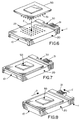
- Figures 6-8 show a PGA package 50, such as a semi-conductor package or the like, having a plurality of lead pins 51 depending therefrom in a grid array.
- the number of lead pins and corresponding number of through holes 23 in slide plate 20 of socket 1 do not correspond to the depiction of Figure 1 or subsequent Figures 9, 11 and 13, whereby Figure 6 is somewhat schematic.
- PGA package 50 is positioned onto the top of slide plate 20 in the direction of arrow "E" (Fig. 6). Lead pins 51 enter through holes 23 with zero insertion forces, until PGA package 50 rests on top of slide plate 20 as seen in Figure 7. In this open position, slide actuator 30 is in its open position.
- Figure 8 shows the slide actuator having been moved in the direction of arrow "C” corresponding to the position shown in Figure 3. As will be described hereinafter, this sliding movement of the slide actuator causes slide plate 20 to move in the direction of arrow "D.”
- FIG 10 shows one of the lead pins 51 from PGA package 50 (Fig. 6) inserted through one of the through holes 23 in slide plate 20.
- the lead pin is positioned within one of a plurality of terminals, generally designated 40, which are mounted within terminal-receiving passages 15 (Fig. 1) in base housing 10.
- each terminal 40 includes a pair of side guide portions 41 and a contact portion 42 which angles inwardly from one of the guide portions.
- Lead pin 51 is inserted between the side guide portions with insertion force. As will be seen below, the lead pin is driven into engagement with contact portion 42 when slide plate 20 is driven by slide actuator 30.
- Figure 9 shows the condition of socket 1 in its open position with Figure 10 showing lead pin 51 inserted freely into terminal 40. It can be seen in Figure 9 that cam follower pin 25 is located at one end of cam slot 32 at the flat land area 38 thereof. Slide plate 20 and slide actuator 30 are in their respective open positions.
- FIG 11 shows slide actuator 30 having been moved partially in the direction of arrow "C” which is effective to drive cam following pin 25 partially along oblique portion 34 of cam slot 32.
- This drives slide plate 20 partially in the direction of arrow "D”.
- lead pin 51 has been driven in the direction of arrow "G” by its engagement within through hole 23 of the sliding plate 20. Consequently, lead pin 51 is driven into engagement with angled contact portion 42 of terminal 40.
- Figure 13 shows slide actuator 30 having been moved completely in the direction of arrow "C” to its closed or engagement position whereat slide plate 20 has been driven completely in the direction of arrow “D” to its engagement position.
- Cam follower pin 25 now has been driven to the opposite end of cam slot 32 and rests at land area 39 of the slot.
- Figure 14 shows that lead pin 51 now has been driven in the direction of arrow "G” completely to its fully terminated position whereat the lead pin engages contact portion 42 and biases the contact portion laterally in the direction of arrow "H”.
- the PGA package now is completely terminated to socket 1.
- slide actuator 30 In order to remove the PGA package from the socket, slide actuator 30 simply is moved back opposite the direction of arrow "C” in Figures 13 and 11 until the slide actuator reaches its open position of Figure 9. This sliding movement of the slide actuator causes slide plate 20 to move back opposite the direction of arrows "D” and moves lead pins 51 back out of engagement with contact portions 42 of terminals 40.
Landscapes
- Engineering & Computer Science (AREA)
- Microelectronics & Electronic Packaging (AREA)
- Connecting Device With Holders (AREA)
- Coupling Device And Connection With Printed Circuit (AREA)
Applications Claiming Priority (2)
| Application Number | Priority Date | Filing Date | Title |
|---|---|---|---|
| JP19638499 | 1999-07-09 | ||
| JP19638499 | 1999-07-09 |
Publications (2)
| Publication Number | Publication Date |
|---|---|
| EP1081993A2 true EP1081993A2 (fr) | 2001-03-07 |
| EP1081993A3 EP1081993A3 (fr) | 2001-09-19 |
Family
ID=16356988
Family Applications (1)
| Application Number | Title | Priority Date | Filing Date |
|---|---|---|---|
| EP00114571A Withdrawn EP1081993A3 (fr) | 1999-07-09 | 2000-07-07 | Socle pour boítier dont les broches sont rangées en grille |
Country Status (7)
| Country | Link |
|---|---|
| US (1) | US6435893B1 (fr) |
| EP (1) | EP1081993A3 (fr) |
| KR (1) | KR100344045B1 (fr) |
| CN (1) | CN1175532C (fr) |
| MY (1) | MY124038A (fr) |
| SG (1) | SG89335A1 (fr) |
| TW (1) | TW475789U (fr) |
Families Citing this family (11)
| Publication number | Priority date | Publication date | Assignee | Title |
|---|---|---|---|---|
| US6613284B2 (en) * | 2001-02-01 | 2003-09-02 | V&P Scientific, Inc. | Microarrayer |
| JP3715545B2 (ja) * | 2001-04-19 | 2005-11-09 | タイコエレクトロニクスアンプ株式会社 | 電気コネクタ |
| JP2002329562A (ja) * | 2001-04-25 | 2002-11-15 | Molex Inc | ピングリッドアレイパッケージ用ソケット |
| US6508659B1 (en) * | 2002-03-01 | 2003-01-21 | Hon Hai Precision Ind. Co., Ltd. | Electrical socket having a backup means |
| TW547828U (en) * | 2002-06-13 | 2003-08-11 | Hon Hai Prec Ind Co Ltd | ZIF socket connector |
| US6734548B1 (en) * | 2002-11-20 | 2004-05-11 | Intel Corporation | High-power double throw lever zip socket |
| US6979218B2 (en) * | 2003-01-29 | 2005-12-27 | Tyco Electronics Corporation | Lever actuated socket with state indicator |
| US7244136B2 (en) * | 2003-01-30 | 2007-07-17 | Molex Incorporated | ZIF electrical connector |
| US6929497B1 (en) * | 2004-06-30 | 2005-08-16 | Suyin Corporation | CPU socket |
| US7173804B2 (en) * | 2004-09-28 | 2007-02-06 | Intel Corporation | Array capacitor with IC contacts and applications |
| CN103617964B (zh) * | 2013-11-20 | 2019-03-29 | 常州唐龙电子有限公司 | 一种铜镍合金封装针栅阵列式集成电路 |
Family Cites Families (7)
| Publication number | Priority date | Publication date | Assignee | Title |
|---|---|---|---|---|
| CA1285036C (fr) * | 1986-12-26 | 1991-06-18 | Kyoichiro Kawano | Connecteur electrique |
| US5454727A (en) * | 1994-02-10 | 1995-10-03 | Hsu; Fu-Yu | Electrical connector with ZIF socket |
| US5562474A (en) * | 1994-10-13 | 1996-10-08 | Land Win Electronic Corp. | Base body and terminal of a socket assembly for an integrated circuit chip |
| JP2667646B2 (ja) * | 1994-12-29 | 1997-10-27 | 山一電機株式会社 | Icソケット |
| US5855489A (en) * | 1997-05-12 | 1999-01-05 | The Whitaker Corporation | Low profile actuator for ZIF socket |
| US5967824A (en) * | 1998-02-11 | 1999-10-19 | International Business Machines Corporation | Mechanism for inserting or removing I/O cards with internal connectors |
| US6083028A (en) * | 1998-10-07 | 2000-07-04 | Hon Hai Precision Ind. Co., Ltd. | ZIF PGA socket |
-
2000
- 2000-06-27 SG SG200003588A patent/SG89335A1/en unknown
- 2000-07-07 MY MYPI20003133 patent/MY124038A/en unknown
- 2000-07-07 EP EP00114571A patent/EP1081993A3/fr not_active Withdrawn
- 2000-07-08 CN CNB001227297A patent/CN1175532C/zh not_active Expired - Fee Related
- 2000-07-08 KR KR1020000039044A patent/KR100344045B1/ko not_active Expired - Fee Related
- 2000-07-10 US US09/612,995 patent/US6435893B1/en not_active Expired - Fee Related
- 2000-08-01 TW TW089211773U patent/TW475789U/zh not_active IP Right Cessation
Also Published As
| Publication number | Publication date |
|---|---|
| SG89335A1 (en) | 2002-06-18 |
| TW475789U (en) | 2002-02-01 |
| US6435893B1 (en) | 2002-08-20 |
| KR20010015239A (ko) | 2001-02-26 |
| KR100344045B1 (ko) | 2002-07-20 |
| CN1175532C (zh) | 2004-11-10 |
| CN1280407A (zh) | 2001-01-17 |
| EP1081993A3 (fr) | 2001-09-19 |
| MY124038A (en) | 2006-06-30 |
Similar Documents
| Publication | Publication Date | Title |
|---|---|---|
| EP0422584A2 (fr) | Outil pour la mise en oeuvre d'une grille support à force d'insertion nulle | |
| US6435893B1 (en) | Socket for pin grid array package | |
| US6903293B2 (en) | Switch device having good sense of operational touch even when sliding operating knob or rocking operating knob is attached thereto | |
| US4873761A (en) | Insertion/extraction tool | |
| US6776644B2 (en) | Lever actuated ZIF processor socket | |
| US5364284A (en) | Socket | |
| US7494357B2 (en) | Socket with latching equipment | |
| US4665290A (en) | Trigger operated portable electric tool switch | |
| US6464525B2 (en) | Overtravel protection for ZIF electrical connector | |
| US6743034B2 (en) | Socket for electrical parts | |
| CA1294338C (fr) | Connecteur de carte de circuits pour coupe-circuit | |
| US8535079B2 (en) | Burn-in socket having actuating mechanism driven alternatively for driving sliding plate | |
| US6517370B2 (en) | Socket for an electric device with a movable plate that is actuated based on force applied to an actuation member | |
| JPH08339865A (ja) | 簡易操作型電気接触プラグ装置 | |
| JPH0254632B2 (fr) | ||
| US20050233614A1 (en) | Test connector with metallic stiffener | |
| US6004152A (en) | ZIF PGA socket | |
| US6811421B1 (en) | Socket connector with pivoting operating members | |
| US4377319A (en) | Low insertion force dip connector | |
| US20010018286A1 (en) | Engagement means for ZIF electrical connector | |
| EP0241257A1 (fr) | Commutateur électrique à bascule ayant une clé de verrouillage amovible | |
| JP3786353B2 (ja) | 電気部品用ソケット | |
| US12562511B2 (en) | Wire connection terminal structure | |
| EP1006618A2 (fr) | Socle a force d'insertion zero (zif) pour des boitiers de reseau de grille a broche | |
| US5052101A (en) | Tool for use with a ZIF PGA socket |
Legal Events
| Date | Code | Title | Description |
|---|---|---|---|
| PUAI | Public reference made under article 153(3) epc to a published international application that has entered the european phase |
Free format text: ORIGINAL CODE: 0009012 |
|
| AK | Designated contracting states |
Kind code of ref document: A2 Designated state(s): AT BE CH CY DE DK ES FI FR GB GR IE IT LI LU MC NL PT SE Kind code of ref document: A2 Designated state(s): DE FR GB IE IT NL |
|
| AX | Request for extension of the european patent |
Free format text: AL;LT;LV;MK;RO;SI |
|
| PUAL | Search report despatched |
Free format text: ORIGINAL CODE: 0009013 |
|
| AK | Designated contracting states |
Kind code of ref document: A3 Designated state(s): AT BE CH CY DE DK ES FI FR GB GR IE IT LI LU MC NL PT SE |
|
| AX | Request for extension of the european patent |
Free format text: AL;LT;LV;MK;RO;SI |
|
| AKX | Designation fees paid |
Free format text: DE FR GB IE IT NL |
|
| STAA | Information on the status of an ep patent application or granted ep patent |
Free format text: STATUS: THE APPLICATION IS DEEMED TO BE WITHDRAWN |
|
| 18D | Application deemed to be withdrawn |
Effective date: 20020320 |