EP1081994A2 - Dispositif d 'alignement et de montage de deux plaquettes de circuit - Google Patents
Dispositif d 'alignement et de montage de deux plaquettes de circuit Download PDFInfo
- Publication number
- EP1081994A2 EP1081994A2 EP00203017A EP00203017A EP1081994A2 EP 1081994 A2 EP1081994 A2 EP 1081994A2 EP 00203017 A EP00203017 A EP 00203017A EP 00203017 A EP00203017 A EP 00203017A EP 1081994 A2 EP1081994 A2 EP 1081994A2
- Authority
- EP
- European Patent Office
- Prior art keywords
- connector
- securement
- cylindrical section
- boards
- landings
- Prior art date
- Legal status (The legal status is an assumption and is not a legal conclusion. Google has not performed a legal analysis and makes no representation as to the accuracy of the status listed.)
- Granted
Links
Images


Classifications
-
- H—ELECTRICITY
- H05—ELECTRIC TECHNIQUES NOT OTHERWISE PROVIDED FOR
- H05K—PRINTED CIRCUITS; CASINGS OR CONSTRUCTIONAL DETAILS OF ELECTRIC APPARATUS; MANUFACTURE OF ASSEMBLAGES OF ELECTRICAL COMPONENTS
- H05K7/00—Constructional details common to different types of electric apparatus
- H05K7/14—Mounting supporting structure in casing or on frame or rack
- H05K7/1417—Mounting supporting structure in casing or on frame or rack having securing means for mounting boards, plates or wiring boards
- H05K7/142—Spacers not being card guides
Definitions
- the present invention relates generally to devices for alignment and connection of planar electronic components such as printed circuit boards. More particularly, the present invention relates to an improved board-to-board securement device for successful alignment and connection of adjacent, planar components in spaced parallel relation in an electronic device or system so as to prevent overcompression of elastomeric contact elements positioned therebetween.
- I/O input/output
- MPI contacts are elastomeric contacts which integrate semi-conductive material therein.
- the MPI contacts are designed to provide an electrically and mechanically reliable, low-cost interconnection method for high-density printed circuit board (“PCB”) components without the use of metal pins or solder techniques.
- the conductive path has similar electrical properties to a metal pin or solder contact.
- the MPI material an elastomeric material with semiconductive particles dispersed therein, is formed into tiny micro columns and held in a grid pattern by a thin polyamide substrate which aligns with the lands of a packaged silicon device and the landing pad of the PCB. When mechanically compressed, the micro columns align with the pads on an LGA package and the landing pads of a PCB, forming a conductive path therebetween.
- the flexible polymer/metallization columns act as shock absorbers allowing for excellent performance under extreme shock/vibration testing. Also, the elasticity of the polymeric column acts as a seal to the environment at the point of connection, protecting the connection from harmful elements.
- MPI technology is seen as a solution to integrating high-density microprocessors and other silicon devices onto the motherboard, both in terms of I/O count as well as the potential for far lower costs than other interconnections.
- the MPI technology has the potential to double or even triple the upper limit for I/O. With a higher density interconnection technology such as this, designers will be able to integrate the functions of several chips into a single piece of silicon, thereby reducing the number of components, interconnections and overall size of the PCBs. At a low cost per contact with an integral heat sink, and exceptionally low tooling costs, MPI has great potential to replace most of the interconnects in PCS, laptops and other electronic devices.
- MPI contacts are not only desirable because of their superior mechanical, electrical and thermal performance, but also because of the cost per contact is significantly lower than mechanically complex cartridge-type interconnects or conventional board-to-board, metal pin-and-socket or BGA devices.
- the MPI material's polymer/metallization combination also provides superior resistance to environmental and shock/vibration conditions as well as excellent conductive performance, both electrically and thermally.
- a locating pin is mounted on a connector that protrudes above and below the connector.
- the locating pin aligns the connector to a pair of planar elements such as a motherboard and daughtercard by holes located in the boards just for this purpose.
- Examples of such connectors include U.S. Patent No. 4,309,856 to Varnau et al. which discloses a resilient device for securing panels in parallel spaced relation to a support bracket; U.S. Patent No. 4,760,495 to Till, which provides a "stand-off device” to control the spacing between adjacent planar elements in electronic instrumentation; and U.S. Patent No. 4,875,140 to Delpech which discloses a support device for printed circuit boards formed by a column having at least one base on which a circuit board is to be supported with the boards and a coupling member fixed by a screw.
- the present invention provides a securement device to align adjacent printed circuit boards, such as a motherboard and daughtercard (collectively "PCBs"), while simultaneously connecting all external hardware so as to prevent overcompression of elastomeric contacts positioned therebetween during assembly.
- the device supports a connector between a pair of PCBs in spaced parallel relation, wherein the connector itself supports a plurality of elastomeric contacts thereon for establishing electrical engagement between the PCBs.
- the PCBs and the connector each include aligned securement openings.
- the device includes an elongate fastener having a substantially cylindrical section positioned in the connector opening.
- the cylindrical section defines a pair of opposed, substantially planar spaced apart component landings for support of a planar component such as a PCB thereupon.
- the landings are spaced apart a distance sufficient to place the PCBs in electrical engagement with the connector without overcompressing the elastomeric contacts therebetween.
- a substantially annular shoulder is concentrically defined on each of the landings and extends longitudinally therefrom. Such shoulder has an outer diameter smaller than an outer diameter of said cylindrical section.
- a fastening element extends longitudinally from at least one of said top and bottom shoulders for fastening of the securement element to a housing member accommodating the PCBs and connector therein.
- a diametrical slotted cavity is defined in one landing and shoulder which accommodates a torquing element therein.
- the slotted cavity provides access to an internally threaded bore which is defined along the length of the slot and can be defined along the longitudinal extent of the cylindrical section itself.
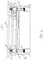
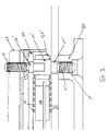
- FIG. 1 shows an assembly 1 of electronic components utilizing an alignment and securement device 10.
- Securement device 10 is a substantially cylindrical, internally threaded member adapted for insertion between planar components, such as motherboard 60 and daughtercard 70 (collectively "boards").
- Securement device 10 secures such boards to one another so as to accommodate placement of an interconnection device therebetween, such as MPI connector 50.
- a heatsink or heat spreader plate 40 can also be incorporated into the assembly to provide additional support and dissipate excess heat.
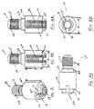
- a preferred embodiment of the securement device 10 is an elongate member including a substantially cylindrical section 12 having a predetermined height H and a large outer diameter D.
- Section 12 has a bottom extremity defined by a substantially planar landing 20 forming an annular platform adjacent cylindrical section 12.
- Landing 20 has a small, generally annular shoulder 21 protruded longitudinally therefrom which is concentrically defined thereon.
- Section 12 also includes a top extremity defined by a substantially planar landing 22 forming an annular platform at an opposing portion of cylindrical section 12.
- Landing 22 also has a small, generally annular shoulder 24 protruding longitudinally therefrom and concentrically defined thereon.
- a diametrical slotted cavity 16 is provided in shoulder 21.
- Slotted cavity 16 has a predetermined width and depth defined in cylindrical section 12 to accommodate insertion of a torque member therein, such as a straight edge screwdriver.
- Slotted cavity 16 provides access to an internally threaded bore 18 by a fastening member, such as a fastening screw having a threaded configuration corresponding to that of bore 18. Tapping of threaded bore 18 can extend well into the interior of section 12 and may span height H thereof.
- a fastening element 14 depends from the top extremity of cylindrical section 12.
- Fastening element 14 is shown herein as an external male threaded element having a plurality of threads 15 defined thereon.
- Fastening element 14 has a length and diameter sufficient to threadably engage a housing 80 so as to securely fasten planar components therewithin.
- fastening element 14 is shown as a helical thread, it is understood that it may comprise any other fastening element conducive to the function of the present invention, such as a nut and bolt combination.
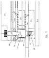
- Securement device 10 is insertably aligned in an electronic assembly 1 such as that shown in Figure 3.
- Motherboard 60 and daughtercard 70 are placed in spaced parallel relation so as to be in alignment with one another 70.
- a support or bolster plate 80 may be inserted adjacent motherboard 60 and atop plastic case 30 to provide additional compression and support of the electronic assembly.
- Securement device 10 is inserted into the assembly such that top shoulder 23 is insertably accommodated in a corresponding aperture in motherboard 60 (not shown).
- Cylindrical section 12 resides in a corresponding aperture provided in connector 50, such aperture being in alignment with the aperture in motherboard 60.
- Fastening element 14 engages (and in this case, is threadably secured to) support plate 80, the support plate providing a threaded orifice corresponding to fastening element 14.
- the external threads 15 are then screwed in to support plate 80 located directly beneath the connector area and further into threaded bosses on plastic case 30 located there beneath. In this manner, the support plate and fastening element can be secured to one another to effect securement and alignment of support plate 80 to motherboard 60.
- MPI connector 50 is placed alongside cylindrical section 12 such that a plurality of resilient elements 55 supported by connector 50 are in mechanical and electrical engagement with the boards 60 and 70.
- Landing 22 compresses motherboard 60 therebeneath, and landing 20 supports daughtercard 70 thereon.
- the large outside diameter of cylindrical section 12, in combination with shoulders 21 and 23, ensures securement of the connector to both boards, thereby minimizing any tolerance stack-up usually associated with multiple component assemblies and preventing the user from overcompressing contacts 55.
- MPI connector 50 supports a plurality of MPI contacts 55 thereon.
- Each of electrical contacts 55 is made from an electrically conductive material of the type fabricated from a high temperature flexible conductive polymer having medalist particles embedded therein.
- Such a layer may be made from the combination of an elastic insulative polymeric material and a conductive material, such as a plurality of conductive flakes, as disclosed in commonly assigned U.S. Patent No. 5,871,842 and incorporated by reference herein.
- a layered composition comprising a substrate and a thermoplastic elastomer barrier layer may be provided.
- the substrate may be fabricated from an elastic material such as silicone rubber, a flexible material such as the thermoplastic polyamide (“Nylon”) or a rigid material such as thermoplastic polyamide-imide (“Ultem”).
- the barrier layer may be fabricated of a thermoplastic elastomer such as a thermoplastic polyurethane elastomer or a thermoplastic polyolefin elastomer.
- the conductive flakes may be fabricated of a conductive or semiconductive material such as silver, nickel or carbon. The size of the flakes varies with the level of conductivity required for a particular application, and particularly with respect to establishment of a sufficient electrical connection between the elastomeric element and a chip card in contact therewith.
- Daughtercard 70 is then placed overlying elastomeric elements 55 such that the daughtercard engages shoulder 20.
- This small shoulder located on the top of internally threaded bore 18 aligns with a hole in the daughtercard (not shown.)
- Securement device 10 is thereafter torqued by a tool (i.e. standard screwdriver) inserted into diametrical slotted cavity 16 designated for this purpose. Because securement device 10 is a turned screw machined part, positional tolerances can be held very tightly.
- Heatsink plate 40 is then placed in overlying alignment with daughtercard 70, and the entire assembly is fastened by a securement element such as fastening screw 35.
- Fastening screw 35 is insertable through heatsink plate 40 and directly infiltrates threaded bore 18 for securement therewith to provide additional securement of the assembly components.
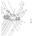
- a securement device 10' is provided having similar features to those of securement device 10 described hereinabove.
- An elongate securement section 90 extends laterally in relation to shoulder 21.
- elongate securement section 90 is shown as an external male threaded element having a plurality of helical threads 91 thereon.
- Securement section 90 is long enough to protrude above the heatsink plate 40 and fasten using a nut and washer instead of a screw.
- the use of securement device 10' is similar to that of securement device 10, and its implementation in an electronic component system is illustrated fully in Figures 6 and 7.
- the present invention obviates the requirement for extra openings in PCBs to accommodate fastening hardware by providing a device that threadably engages corresponding threaded portions and provides easy access for conventional fastening tools (i.e.. a screwdriver) to tighten the connector and thereby attain alignment of the boards.
- This invention further allows MPI contacts to be mounted and aligned using existing components to prevent overcompression of the contacts during assembly.
Landscapes
- Engineering & Computer Science (AREA)
- Microelectronics & Electronic Packaging (AREA)
- Coupling Device And Connection With Printed Circuit (AREA)
- Combinations Of Printed Boards (AREA)
- Measuring Leads Or Probes (AREA)
- Mounting Of Printed Circuit Boards And The Like (AREA)
Applications Claiming Priority (2)
| Application Number | Priority Date | Filing Date | Title |
|---|---|---|---|
| US09/387,885 US6280202B1 (en) | 1999-09-01 | 1999-09-01 | Board-to-board alignment and securement device |
| US387885 | 1999-09-01 |
Publications (3)
| Publication Number | Publication Date |
|---|---|
| EP1081994A2 true EP1081994A2 (fr) | 2001-03-07 |
| EP1081994A3 EP1081994A3 (fr) | 2001-09-26 |
| EP1081994B1 EP1081994B1 (fr) | 2007-07-11 |
Family
ID=23531711
Family Applications (1)
| Application Number | Title | Priority Date | Filing Date |
|---|---|---|---|
| EP00203017A Expired - Lifetime EP1081994B1 (fr) | 1999-09-01 | 2000-08-29 | Dispositif d 'alignement et de montage de deux plaquettes de circuit |
Country Status (5)
| Country | Link |
|---|---|
| US (1) | US6280202B1 (fr) |
| EP (1) | EP1081994B1 (fr) |
| JP (1) | JP2001148555A (fr) |
| CA (1) | CA2313269A1 (fr) |
| DE (1) | DE60035465T2 (fr) |
Cited By (9)
| Publication number | Priority date | Publication date | Assignee | Title |
|---|---|---|---|---|
| DE10135109A1 (de) * | 2001-07-19 | 2003-02-06 | Conti Temic Microelectronic | Elektronische Baugruppe |
| GB2405750A (en) * | 2003-09-02 | 2005-03-09 | Hewlett Packard Development Co | Apparatus for connecting cicuit boards |
| JP2009519138A (ja) * | 2005-12-16 | 2009-05-14 | エアバス・ユ―ケ―・リミテッド | ファスナアセンブリ |
| GB2487185A (en) * | 2011-01-05 | 2012-07-18 | Pg Drives Technology Ltd | Power Switching Circuitry with electrically conductive standoff and urging mechanism. |
| EP2925105A3 (fr) * | 2014-03-18 | 2016-01-06 | BSH Hausgeräte GmbH | Module électronique pour un appareil ménager et procédé de montage d'un module électronique |
| WO2020171452A1 (fr) | 2019-02-19 | 2020-08-27 | Samsung Electronics Co., Ltd. | Structure d'empilement de cartes de circuit imprimé utilisant un interposeur et dispositif électronique la comprenant |
| CN112105243A (zh) * | 2020-06-05 | 2020-12-18 | 谷歌有限责任公司 | 带有集成对准的散热器和加劲件安装件 |
| US11071195B1 (en) | 2020-06-05 | 2021-07-20 | Google Llc | Heatsink and stiffener mount with integrated alignment |
| US11991864B2 (en) | 2022-03-16 | 2024-05-21 | Google Llc | Load vectoring heat sink |
Families Citing this family (41)
| Publication number | Priority date | Publication date | Assignee | Title |
|---|---|---|---|---|
| US6390829B1 (en) * | 2000-04-25 | 2002-05-21 | Antec Corporation | Electrical connector assembly for a printed circuit board |
| US6360431B1 (en) * | 2000-09-29 | 2002-03-26 | Intel Corporation | Processor power delivery system |
| US6776623B1 (en) * | 2001-06-11 | 2004-08-17 | Picolight Incorporated | Transceiver mounting adapters |
| US7344792B2 (en) * | 2001-09-19 | 2008-03-18 | Ballard Power Systems Inc. | Electrical contacting device for a fuel cell |
| ES1050900Y (es) * | 2001-12-31 | 2003-03-16 | Lear Automotive Eeds Spain | Caja de distribucion electrica con sistema de compactacion para sus elementos integrantes. |
| US20040120124A1 (en) * | 2002-12-18 | 2004-06-24 | Patrick Cauwels | Structure and method for positively locating components |
| US7469507B2 (en) * | 2003-02-18 | 2008-12-30 | Sage Of America, Inc. | Refractory system having improved anchoring stud |
| US7053496B2 (en) * | 2003-06-27 | 2006-05-30 | Intel Corporation | Hybrid package with non-insertable and insertable conductive features, complementary receptacle, and methods of fabrication, assembly, and operation therefor |
| US6773268B1 (en) * | 2003-06-27 | 2004-08-10 | Hon Hai Precision Ind. Co., Ltd | Holddown for circuit boards |
| US6960092B1 (en) * | 2003-07-25 | 2005-11-01 | Advanced Micro Devices, Inc. | Compression mount and zero insertion force socket for IC devices |
| TWI272042B (en) * | 2003-12-31 | 2007-01-21 | Benq Corp | Structure of multi-layered printed circuit board with a spacer post |
| JP4055719B2 (ja) * | 2004-02-20 | 2008-03-05 | セイコーエプソン株式会社 | 電子機器用筐体およびこの電子機器用筐体を備えたプロジェクタ |
| US7090507B2 (en) * | 2004-02-27 | 2006-08-15 | Tyco Electronics Corporation | Socket having substrate locking feature |
| JP4214950B2 (ja) * | 2004-05-12 | 2009-01-28 | 船井電機株式会社 | プリント基板支持構造 |
| US7619899B2 (en) * | 2004-08-17 | 2009-11-17 | Hewlett-Packard Development Company, L.P. | Securable electronic module |
| JP2006085947A (ja) * | 2004-09-14 | 2006-03-30 | Toshiba Corp | コネクタ装置、コネクタ装置の保持方法およびコネクタ装置を有する電子機器 |
| US7061766B2 (en) * | 2004-09-23 | 2006-06-13 | Hamilton Sunstrand Corporation | Combination IGBT mounting method |
| US7479020B2 (en) * | 2004-11-22 | 2009-01-20 | Visteon Global Technologies, Inc. | Electronic control module having an internal electric ground |
| US7484530B2 (en) * | 2005-04-22 | 2009-02-03 | Parker-Hannifin Corporation | Dual purpose alignment and fluid coupling |
| US20070254714A1 (en) * | 2006-05-01 | 2007-11-01 | Martich Mark E | Wireless access point |
| US20090016846A1 (en) * | 2007-07-09 | 2009-01-15 | Dragonstate Technology Co., Ltd. | Anchor structure for electronic card connectors |
| CN201130740Y (zh) * | 2007-08-17 | 2008-10-08 | 富士康(昆山)电脑接插件有限公司 | 电连接器组件 |
| JP2009164387A (ja) * | 2008-01-08 | 2009-07-23 | Fujitsu Ltd | プリント基板ユニット及びプリント基板ユニットの固定具 |
| TW201228537A (en) * | 2010-12-29 | 2012-07-01 | Hon Hai Prec Ind Co Ltd | Fixing structure for circuit board |
| CN102548327B (zh) * | 2010-12-30 | 2016-03-09 | 赛恩倍吉科技顾问(深圳)有限公司 | 电路板固定结构 |
| US20130259601A1 (en) * | 2012-03-30 | 2013-10-03 | Alcatel-Lucent Canada, Inc. | Low Profile Standoff With Tool Stop |
| US9515398B2 (en) | 2012-11-28 | 2016-12-06 | Robert Bosch Gmbh | Mechanical spacer with non-spring electrical connections for a multiple printed circuit board assembly |
| CN105144488B (zh) * | 2013-08-19 | 2017-07-21 | 保力马科技(日本)株式会社 | 连接器 |
| US20150103501A1 (en) * | 2013-10-16 | 2015-04-16 | Kabushiki Kaisha Toshiba | Electronic apparatus |
| WO2015077176A1 (fr) * | 2013-11-22 | 2015-05-28 | Samtec, Inc. | Entretoise d'aide de découplage en deux pièces |
| TWM475794U (en) * | 2013-12-02 | 2014-04-01 | Giga Byte Tech Co Ltd | Stud |
| DE202015105092U1 (de) * | 2015-09-28 | 2015-10-29 | Tbs Avionics Co Ltd | Elektronisches Bauteil |
| CN105576416B (zh) * | 2016-01-14 | 2020-04-24 | 富士康(昆山)电脑接插件有限公司 | 电连接器组件 |
| KR102589304B1 (ko) * | 2016-06-22 | 2023-10-16 | 삼성전자주식회사 | 커넥터 장치 및 이를 구비한 전자 장치 |
| US10720719B2 (en) * | 2016-10-25 | 2020-07-21 | Hamilton Sundstrand Corporation | Jackscrew assemblies for circuit board connections |
| US10103466B1 (en) * | 2017-05-17 | 2018-10-16 | General Electric Company | Double-threaded connector |
| US10959343B2 (en) * | 2017-08-25 | 2021-03-23 | Hewlett Packard Enterprise Development Lp | Integrated stand-offs for printed circuit boards |
| US10218098B1 (en) * | 2017-08-28 | 2019-02-26 | Finisar Corporation | Module mount interposer |
| CN121726742A (zh) * | 2020-11-30 | 2026-03-24 | 三星电子株式会社 | 包括加固构件的电子设备 |
| WO2024025106A1 (fr) * | 2022-07-29 | 2024-02-01 | 삼성전자주식회사 | Dispositif électronique comprenant une structure de vis empilée |
| US20250120033A1 (en) * | 2023-10-04 | 2025-04-10 | Hamilton Sundstrand Corporation | Standoff for circuit card assemblies |
Family Cites Families (17)
| Publication number | Priority date | Publication date | Assignee | Title |
|---|---|---|---|---|
| US1864080A (en) * | 1927-12-10 | 1932-06-21 | Mechanical Rubber Co | Nonmetallic connection |
| US3356904A (en) | 1966-12-07 | 1967-12-05 | Rlf Ind Inc | Heat dissipating arrangement for electrical components |
| US4309856A (en) | 1980-05-22 | 1982-01-12 | General Motors Corporation | Panel mounting device and assembly |
| DE3231114A1 (de) * | 1982-08-20 | 1984-02-23 | Albrecht 8059 Eitting Riepertinger | Verbindungssystem |
| JPS60133684U (ja) * | 1984-02-13 | 1985-09-06 | 北川工業株式会社 | プリント基板保持具 |
| USD293880S (en) | 1985-03-13 | 1988-01-26 | Kitagawa Industries Co., Ltd. | Spacer and securing unit |
| US4760495A (en) | 1987-04-16 | 1988-07-26 | Prime Computer Inc. | Stand-off device |
| FR2615065B1 (fr) * | 1987-05-06 | 1989-07-28 | Trt Telecom Radio Electr | Support pour plaques de circuits imprimes |
| US4855873A (en) * | 1988-06-03 | 1989-08-08 | Hayes Microcomputer Products, Inc. | Standoff and grounding clip assembly |
| US4969065A (en) * | 1989-02-28 | 1990-11-06 | Petri Hector D | Spacer for circuit boards and circuit board assembly including same |
| US5018982A (en) * | 1990-07-25 | 1991-05-28 | Ncr Corporation | Adapter for stacking printed circuit boards |
| US5281149A (en) * | 1992-07-06 | 1994-01-25 | Petri Hector D | Grounding circuit board standoff |
| US5473510A (en) * | 1994-03-25 | 1995-12-05 | Convex Computer Corporation | Land grid array package/circuit board assemblies and methods for constructing the same |
| FR2726428B1 (fr) | 1994-10-27 | 1997-01-10 | Gec Alsthom Transport Sa | Tiroir pour cartes electroniques a embrochement et debrochage automatiques et tiroir et son support |
| SE516315C2 (sv) | 1994-11-07 | 2001-12-17 | Atlas Copco Controls Ab | Styrkretsarrangemang till en drivenhet för en elektrisk motor |
| AU4926396A (en) | 1995-02-16 | 1996-09-04 | Micromodule Systems, Inc. | Multiple chip module mounting assembly and computer using same |
| US5608611A (en) | 1995-10-03 | 1997-03-04 | United Technologies Automotive, Inc./Ford Motor Company | Vehicle electronic module with integral mounting and grounding means |
-
1999
- 1999-09-01 US US09/387,885 patent/US6280202B1/en not_active Expired - Fee Related
-
2000
- 2000-06-30 CA CA002313269A patent/CA2313269A1/fr not_active Abandoned
- 2000-08-29 DE DE60035465T patent/DE60035465T2/de not_active Expired - Lifetime
- 2000-08-29 EP EP00203017A patent/EP1081994B1/fr not_active Expired - Lifetime
- 2000-09-01 JP JP2000265778A patent/JP2001148555A/ja active Pending
Cited By (20)
| Publication number | Priority date | Publication date | Assignee | Title |
|---|---|---|---|---|
| DE10135109A1 (de) * | 2001-07-19 | 2003-02-06 | Conti Temic Microelectronic | Elektronische Baugruppe |
| GB2405750A (en) * | 2003-09-02 | 2005-03-09 | Hewlett Packard Development Co | Apparatus for connecting cicuit boards |
| GB2405750A9 (en) * | 2003-09-02 | 2005-04-25 | Hewlett Packard Development Co | Apparatus for connecting circuit boards |
| US6951466B2 (en) | 2003-09-02 | 2005-10-04 | Hewlett-Packard Development Company, L.P. | Attachment plate for directly mating circuit boards |
| GB2405750B (en) * | 2003-09-02 | 2006-08-16 | Hewlett Packard Development Co | Apparatus and method for connecting circuit boards |
| US7112069B2 (en) | 2003-09-02 | 2006-09-26 | Hewlett-Packard Development Company, L.P. | Attachment plate for directly mating circuit boards |
| EP1960678B1 (fr) * | 2005-12-16 | 2015-02-25 | Airbus Operations Limited | Ensemble de fixation |
| JP2009519138A (ja) * | 2005-12-16 | 2009-05-14 | エアバス・ユ―ケ―・リミテッド | ファスナアセンブリ |
| GB2487185B (en) * | 2011-01-05 | 2015-06-03 | Penny & Giles Controls Ltd | Power Switching Circuitry |
| US8665596B2 (en) | 2011-01-05 | 2014-03-04 | Pg Drives Technology Limited | Power switching circuitry |
| GB2487185A (en) * | 2011-01-05 | 2012-07-18 | Pg Drives Technology Ltd | Power Switching Circuitry with electrically conductive standoff and urging mechanism. |
| EP2925105A3 (fr) * | 2014-03-18 | 2016-01-06 | BSH Hausgeräte GmbH | Module électronique pour un appareil ménager et procédé de montage d'un module électronique |
| WO2020171452A1 (fr) | 2019-02-19 | 2020-08-27 | Samsung Electronics Co., Ltd. | Structure d'empilement de cartes de circuit imprimé utilisant un interposeur et dispositif électronique la comprenant |
| EP3912438A4 (fr) * | 2019-02-19 | 2022-03-02 | Samsung Electronics Co., Ltd. | Structure d'empilement de cartes de circuit imprimé utilisant un interposeur et dispositif électronique la comprenant |
| CN112105243A (zh) * | 2020-06-05 | 2020-12-18 | 谷歌有限责任公司 | 带有集成对准的散热器和加劲件安装件 |
| US11071195B1 (en) | 2020-06-05 | 2021-07-20 | Google Llc | Heatsink and stiffener mount with integrated alignment |
| EP3920216A1 (fr) * | 2020-06-05 | 2021-12-08 | Google LLC | Dissipateur thermique et support de raidisseur à alignement intégré |
| CN112105243B (zh) * | 2020-06-05 | 2023-11-28 | 谷歌有限责任公司 | 具有加劲件安装件的电子组件及其组装方法 |
| TWI840625B (zh) * | 2020-06-05 | 2024-05-01 | 美商谷歌有限責任公司 | 電子總成及組裝電子組件之方法 |
| US11991864B2 (en) | 2022-03-16 | 2024-05-21 | Google Llc | Load vectoring heat sink |
Also Published As
| Publication number | Publication date |
|---|---|
| JP2001148555A (ja) | 2001-05-29 |
| CA2313269A1 (fr) | 2001-03-01 |
| EP1081994B1 (fr) | 2007-07-11 |
| US6280202B1 (en) | 2001-08-28 |
| DE60035465T2 (de) | 2008-03-13 |
| DE60035465D1 (de) | 2007-08-23 |
| EP1081994A3 (fr) | 2001-09-26 |
Similar Documents
| Publication | Publication Date | Title |
|---|---|---|
| EP1081994B1 (fr) | Dispositif d 'alignement et de montage de deux plaquettes de circuit | |
| US9209540B2 (en) | Board-to-board connectors | |
| US5590026A (en) | Apparatus for dissipating heat from an integrated circuit | |
| US6709277B2 (en) | System and method for connecting a power converter to a land grid array socket | |
| USRE35733E (en) | Device for interconnecting integrated circuit packages to circuit boards | |
| JP3859728B2 (ja) | 電力パッド/電力配給システム | |
| CN100541936C (zh) | 用于集成电路的电力输送系统 | |
| US6658730B2 (en) | Processor power delivery system | |
| US7005586B1 (en) | Supplying power/ground to a component having side power/ground pads | |
| US6545871B1 (en) | Apparatus for providing heat dissipation for a circuit element | |
| US9807905B2 (en) | Adapter cooling apparatus and method for modular computing devices | |
| US6603665B1 (en) | Heat dissipating assembly with thermal plates | |
| US6461169B1 (en) | Interconnecting circuit modules to a motherboard using an edge connector with conductive polymer contacts | |
| WO2008102326A2 (fr) | Découplage dans la grille pour dispositifs à grille matricielle à billes (bga) | |
| US6392887B1 (en) | PLGA-BGA socket using elastomer connectors | |
| US6360431B1 (en) | Processor power delivery system | |
| KR20020092961A (ko) | 통합된 열 및 emi 제어로 마이크로프로세서에 전력을공급하기 위한 방법 및 장치 | |
| US5999414A (en) | Physically separating printed circuit boards with a resilient, conductive contact | |
| US20030150645A1 (en) | Method and apparatus for coupling a microelectronic device package to a circuit board | |
| US6672892B2 (en) | Package retention module coupled directly to a socket | |
| CN217957634U (zh) | 用于散热装置的连接结构、散热装置以及电子设备 | |
| US7360586B2 (en) | Wrap around heat sink apparatus and method | |
| JP4808032B2 (ja) | 圧縮荷重適応ソケット | |
| US6485311B2 (en) | Compression connector actuation system | |
| US6626681B2 (en) | Integrated socket for microprocessor package and cache memory |
Legal Events
| Date | Code | Title | Description |
|---|---|---|---|
| PUAI | Public reference made under article 153(3) epc to a published international application that has entered the european phase |
Free format text: ORIGINAL CODE: 0009012 |
|
| AK | Designated contracting states |
Kind code of ref document: A2 Designated state(s): DE FR GB Kind code of ref document: A2 Designated state(s): AT BE CH CY DE DK ES FI FR GB GR IE IT LI LU MC NL PT SE |
|
| AX | Request for extension of the european patent |
Free format text: AL;LT;LV;MK;RO;SI |
|
| PUAL | Search report despatched |
Free format text: ORIGINAL CODE: 0009013 |
|
| AK | Designated contracting states |
Kind code of ref document: A3 Designated state(s): AT BE CH CY DE DK ES FI FR GB GR IE IT LI LU MC NL PT SE |
|
| AX | Request for extension of the european patent |
Free format text: AL;LT;LV;MK;RO;SI |
|
| RAP1 | Party data changed (applicant data changed or rights of an application transferred) |
Owner name: THOMAS & BETTS INTERNATIONAL, INC. |
|
| 17P | Request for examination filed |
Effective date: 20020314 |
|
| AKX | Designation fees paid |
Free format text: DE FR GB |
|
| GRAP | Despatch of communication of intention to grant a patent |
Free format text: ORIGINAL CODE: EPIDOSNIGR1 |
|
| GRAS | Grant fee paid |
Free format text: ORIGINAL CODE: EPIDOSNIGR3 |
|
| GRAA | (expected) grant |
Free format text: ORIGINAL CODE: 0009210 |
|
| AK | Designated contracting states |
Kind code of ref document: B1 Designated state(s): DE FR GB |
|
| REG | Reference to a national code |
Ref country code: GB Ref legal event code: FG4D |
|
| REF | Corresponds to: |
Ref document number: 60035465 Country of ref document: DE Date of ref document: 20070823 Kind code of ref document: P |
|
| ET | Fr: translation filed | ||
| PLBE | No opposition filed within time limit |
Free format text: ORIGINAL CODE: 0009261 |
|
| STAA | Information on the status of an ep patent application or granted ep patent |
Free format text: STATUS: NO OPPOSITION FILED WITHIN TIME LIMIT |
|
| 26N | No opposition filed |
Effective date: 20080414 |
|
| PGFP | Annual fee paid to national office [announced via postgrant information from national office to epo] |
Ref country code: FR Payment date: 20090817 Year of fee payment: 10 |
|
| PGFP | Annual fee paid to national office [announced via postgrant information from national office to epo] |
Ref country code: GB Payment date: 20090825 Year of fee payment: 10 |
|
| PGFP | Annual fee paid to national office [announced via postgrant information from national office to epo] |
Ref country code: DE Payment date: 20090827 Year of fee payment: 10 |
|
| GBPC | Gb: european patent ceased through non-payment of renewal fee |
Effective date: 20100829 |
|
| REG | Reference to a national code |
Ref country code: FR Ref legal event code: ST Effective date: 20110502 |
|
| REG | Reference to a national code |
Ref country code: DE Ref legal event code: R119 Ref document number: 60035465 Country of ref document: DE Effective date: 20110301 |
|
| PG25 | Lapsed in a contracting state [announced via postgrant information from national office to epo] |
Ref country code: DE Free format text: LAPSE BECAUSE OF NON-PAYMENT OF DUE FEES Effective date: 20110301 Ref country code: FR Free format text: LAPSE BECAUSE OF NON-PAYMENT OF DUE FEES Effective date: 20100831 |
|
| PG25 | Lapsed in a contracting state [announced via postgrant information from national office to epo] |
Ref country code: GB Free format text: LAPSE BECAUSE OF NON-PAYMENT OF DUE FEES Effective date: 20100829 |