EP1082193B1 - Verfahren und einrichtung zur durchführung von arbeitsschritten an miniaturisierten baugruppen - Google Patents
Verfahren und einrichtung zur durchführung von arbeitsschritten an miniaturisierten baugruppen Download PDFInfo
- Publication number
- EP1082193B1 EP1082193B1 EP99925016A EP99925016A EP1082193B1 EP 1082193 B1 EP1082193 B1 EP 1082193B1 EP 99925016 A EP99925016 A EP 99925016A EP 99925016 A EP99925016 A EP 99925016A EP 1082193 B1 EP1082193 B1 EP 1082193B1
- Authority
- EP
- European Patent Office
- Prior art keywords
- module
- accordance
- module carrier
- laser radiation
- assembly
- Prior art date
- Legal status (The legal status is an assumption and is not a legal conclusion. Google has not performed a legal analysis and makes no representation as to the accuracy of the status listed.)
- Expired - Lifetime
Links
Images



Classifications
-
- B—PERFORMING OPERATIONS; TRANSPORTING
- B23—MACHINE TOOLS; METAL-WORKING NOT OTHERWISE PROVIDED FOR
- B23Q—DETAILS, COMPONENTS, OR ACCESSORIES FOR MACHINE TOOLS, e.g. ARRANGEMENTS FOR COPYING OR CONTROLLING; MACHINE TOOLS IN GENERAL CHARACTERISED BY THE CONSTRUCTION OF PARTICULAR DETAILS OR COMPONENTS; COMBINATIONS OR ASSOCIATIONS OF METAL-WORKING MACHINES, NOT DIRECTED TO A PARTICULAR RESULT
- B23Q7/00—Arrangements for handling work specially combined with or arranged in, or specially adapted for use in connection with, machine tools, e.g. for conveying, loading, positioning, discharging, sorting
- B23Q7/14—Arrangements for handling work specially combined with or arranged in, or specially adapted for use in connection with, machine tools, e.g. for conveying, loading, positioning, discharging, sorting co-ordinated in production lines
- B23Q7/1426—Arrangements for handling work specially combined with or arranged in, or specially adapted for use in connection with, machine tools, e.g. for conveying, loading, positioning, discharging, sorting co-ordinated in production lines with work holders not rigidly fixed to the transport devices
-
- H—ELECTRICITY
- H10—SEMICONDUCTOR DEVICES; ELECTRIC SOLID-STATE DEVICES NOT OTHERWISE PROVIDED FOR
- H10P—GENERIC PROCESSES OR APPARATUS FOR THE MANUFACTURE OR TREATMENT OF DEVICES COVERED BY CLASS H10
- H10P72/00—Handling or holding of wafers, substrates or devices during manufacture or treatment thereof
- H10P72/30—Handling or holding of wafers, substrates or devices during manufacture or treatment thereof for conveying, e.g. between different workstations
-
- H—ELECTRICITY
- H10—SEMICONDUCTOR DEVICES; ELECTRIC SOLID-STATE DEVICES NOT OTHERWISE PROVIDED FOR
- H10P—GENERIC PROCESSES OR APPARATUS FOR THE MANUFACTURE OR TREATMENT OF DEVICES COVERED BY CLASS H10
- H10P72/00—Handling or holding of wafers, substrates or devices during manufacture or treatment thereof
- H10P72/30—Handling or holding of wafers, substrates or devices during manufacture or treatment thereof for conveying, e.g. between different workstations
- H10P72/33—Handling or holding of wafers, substrates or devices during manufacture or treatment thereof for conveying, e.g. between different workstations into and out of processing chamber
- H10P72/3314—Continuous loading and unloading into and out of a processing chamber, e.g. transporting belts within processing chambers
-
- H—ELECTRICITY
- H10—SEMICONDUCTOR DEVICES; ELECTRIC SOLID-STATE DEVICES NOT OTHERWISE PROVIDED FOR
- H10P—GENERIC PROCESSES OR APPARATUS FOR THE MANUFACTURE OR TREATMENT OF DEVICES COVERED BY CLASS H10
- H10P72/00—Handling or holding of wafers, substrates or devices during manufacture or treatment thereof
- H10P72/50—Handling or holding of wafers, substrates or devices during manufacture or treatment thereof for positioning, orientation or alignment
- H10P72/53—Handling or holding of wafers, substrates or devices during manufacture or treatment thereof for positioning, orientation or alignment using optical controlling means
-
- Y—GENERAL TAGGING OF NEW TECHNOLOGICAL DEVELOPMENTS; GENERAL TAGGING OF CROSS-SECTIONAL TECHNOLOGIES SPANNING OVER SEVERAL SECTIONS OF THE IPC; TECHNICAL SUBJECTS COVERED BY FORMER USPC CROSS-REFERENCE ART COLLECTIONS [XRACs] AND DIGESTS
- Y10—TECHNICAL SUBJECTS COVERED BY FORMER USPC
- Y10S—TECHNICAL SUBJECTS COVERED BY FORMER USPC CROSS-REFERENCE ART COLLECTIONS [XRACs] AND DIGESTS
- Y10S414/00—Material or article handling
- Y10S414/135—Associated with semiconductor wafer handling
- Y10S414/141—Associated with semiconductor wafer handling includes means for gripping wafer
-
- Y—GENERAL TAGGING OF NEW TECHNOLOGICAL DEVELOPMENTS; GENERAL TAGGING OF CROSS-SECTIONAL TECHNOLOGIES SPANNING OVER SEVERAL SECTIONS OF THE IPC; TECHNICAL SUBJECTS COVERED BY FORMER USPC CROSS-REFERENCE ART COLLECTIONS [XRACs] AND DIGESTS
- Y10—TECHNICAL SUBJECTS COVERED BY FORMER USPC
- Y10T—TECHNICAL SUBJECTS COVERED BY FORMER US CLASSIFICATION
- Y10T156/00—Adhesive bonding and miscellaneous chemical manufacture
- Y10T156/17—Surface bonding means and/or assemblymeans with work feeding or handling means
- Y10T156/1702—For plural parts or plural areas of single part
Definitions
- Such a method for performing work steps on miniaturized Assemblies that are provided with a holding device Subracks are held in at least one workstation, the Assembly with the subrack to carry out the work steps is brought to several workstations and by relative movement between the rack and one of the several workstations to perform one of the work steps exactly and where the positioning of the assembly for carrying out the work steps compared to the subrack is maintained.
- US-A-5,323,013 is a handling robot for a clean room known to handle wafers and place them in a container.
- the invention is based on the object of To create a process that involves performing a variety of processing steps with simple and exact positioning of an assembly allowed.
- This object is achieved according to the invention in a method of the type described in the introduction solved in that a position of the assembly relative to Subrack by one arranged on the subrack and one Position of the assembly detecting positioning device is determined and that in a workstation controlled relative positioning between Subrack and workstation, or subrack and more Assembly or workstation and assembly guided by arranged on it Position detection elements is performed.
- the positioning of the assembly could be relative to the subrack are also maintained, that the subrack the assembly for the respective Stores processing in the respective workstation, in In this case, however, the assembly would be fixed exactly in the workstation is necessary in order to then turn with the assembly of the subrack has the same accuracy to resume. Aside from being an exact Fixation in the respective workstation a considerable On the other hand, effort means a resumption the assembly through the subrack with a Loss of precision associated.
- Steps for an assembly held by the subrack then perform when the sequence of work steps mechanically non-contact, so that the fixation of the Assembly relative to the subrack no high requirements are placed and therefore no great forces act, which in turn causes the assembly to shift relative to the Subrack lead and thus the accuracy negative could influence.
- the work steps are particularly easy to carry out however, if this by means of electromagnetic radiation be carried out because they are easy to generate and for use the individual steps and for example lets focus.
- such a determination of the position of the assembly is relative to the subrack similar to a calibration can be carried out, that is the deviation of the position of the assembly relative to the rack from an ideal position and thus the positioning for the subsequent steps corrected.
- This procedure creates the possibility when gripping or picking up the Assembly a certain positioning error by the holding device allow, but subsequently to be determined by fine positioning and then again to be taken into account in all subsequent processing, so that the actual picking up of the assembly through the holding direction can be designed simply and not overly precise must become.
- each Workstation a controlled relative positioning between subracks and workstation, guided by position detection elements arranged thereon carried out is, so that always a very high precision with the following work step to be carried out can be.
- non-contact work steps can also be carried out, for example of different kinds, it would be, for example conceivable as a work step an evaporation process with a to provide conventional heating of the material to be evaporated.
- the non-contact work step by means of electromagnetic Radiation is carried out.
- the steps are however, if these with electromagnetic Radiation with spatially uniform distribution of energy density be performed as a whole Machining area same physical interactions take place and also a reducing projection of complex structures on one in the beam path Mask is possible.
- the contactless Working step is carried out by means of laser radiation.
- Beam profile is square or rectangular, because square or rectangular beam profiles are very easy and have them fit together to form larger areas.
- the work steps can be carried out particularly precisely however, if this with pulsed electromagnetic Radiation are carried out with such short pulses that no energy transfer from the electron system during the pulse duration into the phonon system of the solid to be processed is transferred.
- a layer application on the Assembly is carried out by means of laser radiation.
- material to be removed is carried out by the assembly with laser radiation.
- Another possibility of a work step is that Establish a joint connection on the assembly using Energy supply with electromagnetic radiation, preferably also pulsed laser radiation.
- this method can then be particularly efficient further educate, if not just a subrack accordingly a set sequence from a workstation is moved to others, but several racks, in Ideally an approximation of the number of work stations corresponding variety of subracks accordingly a set sequence from one workstation to another is moved so that several racks simultaneously one of the several workstations work together.
- the specified sequence can either be predefined or preferably be freely programmable.
- the subrack is preferred for realizing the mobility provided from workstation to workstation, that the rack relative to a base unit are movable, preferably the work stations opposite the basic unit are arranged fixed. It exists but also the possibility, in addition to the subracks also the workstations relative to the base unit to arrange movable.
- the subracks are preferably on the base unit movable along any given paths, so that the method according to the invention provides the greatest possible flexibility shows.
- the subracks can then be particularly inexpensive move when this is contactless with tax information are supplied and, for example, also contactless measurement data transmit to the central unit.
- this tax information includes information regarding the work steps to be carried out.
- a particularly favorable solution provides that the subrack position-controlled, the means that contactless position detection of the subracks along their paths on the base unit takes place and thus the path of the subrack between two workstations can be controlled without contact.
- Another particularly favorable solution provides for measurement data from the position determination of the subracks transmitted contactlessly to the central unit, for example become.
- the energy via a supply flexible line.
- the subrack be supplied with energy without contact, for example the inductive energy transmission with which the immediately required energy can be transmitted or energy can be transmitted can be stored in the subrack in an energy store, for example an accumulator, is temporarily stored.
- the invention relates to a device for carrying out Steps on miniaturized assemblies, including one with one Holding device for holding the subrack provided and several work stations for performing at least one work step, wherein the rack is movable so that the plurality Workstations through the assembly to carry out the work steps Relative movement of subrack and workstation can be positioned exactly is and that the assembly with the holding device for the implementation the work steps in a single position relative to the subrack is fixable, and wherein a position of the assembly relative to the rack by a arranged on the rack and a position of Module detecting positioning device can be determined and in one Workstation a controlled relative positioning between subracks and workstation, or rack and other assembly or workstation and assembly guided by position detection elements arranged thereon is feasible.
- the assembly on a gripper head can be fixed as a holding device for the subrack.
- the gripper can be designed in a wide variety of ways his. For example, it would be possible to use the gripper to train as an electrostatic gripper, which by means of a Electrostatic drive mechanically engages the assembly.
- a particularly simple type of construction provides that the Gripper head has a vacuum gripper for the assembly, with which the assembly is vacuumed against a contact surface is pulled and fixed non-positively.
- the positioning device could for example be like this be trained to recognize the shape of the assembly and aligns the vacuum gripper accordingly, then to the Access assembly, this access after alignment of the vacuum gripper can be "blind". Even more advantageous it is, however, if the positioning device one assigned to a vacuum chamber of the vacuum gripper Marking on the assembly is recognizable, because in in this case while the vacuum gripper is being accessed recorded the position of the marking on the assembly and thus even while the vacuum grippers are being accessed can be controlled to make the assembly as precise as possible to grab.
- the subrack a Has drive unit with which it is movable relative to the base unit is.
- Such a drive unit can be designed in a wide variety of ways his.
- the subrack is a coupling unit with what energy in the rack, for example can be coupled in inductively.
- the coupling unit is preferably assigned to a work station, so that when positioning the rack near the respective workstation automatically the coupling unit for the coupling of the for the Functions of the rack required energy provides.
- the coupling unit is preferably also for this can be used, rough positioning of the subrack to provide the base unit relative to the respective work station.
- the subrack positioning units with which the gripper head relative to a basic element of the subrack is movable. With This positioning unit can then be used for exact positioning the assembly relative to the respective workstation make.
- a particularly advantageous concept of an inventive Subrack provides that this is a basic element and has a boom supporting the gripper head, preferably the positioning units between the basic element and the boom are effective and thus via the boom also position the gripper head itself exactly.
- the Subrack has a controller with which the Gripper head can be positioned exactly relative to the basic element is.
- control means contactless information transfer with the overall control communicated.
- one of the workstations is provided with a laser radiation source, with which is used to carry out the work steps in this required laser radiation can be generated.
- each of the workstations using laser radiation works with its own laser radiation source Mistake.
- utility models or in small and average quantities are preferably each of the Workstations that work with laser radiation with same laser radiation source by switchable beam switches provided.
- the work station for laser processing is preferably the Module designed so that the laser radiation from a facing an assembly positioned in this workstation Exit opening exits and thus with the laser radiation Processing of the assembly is possible immediately is or even applying material to this assembly, this material for application between the outlet opening for the laser radiation and the assembly is positionable.
- the material for application is preferably on a transparent Carrier applied as a pre-structured, thin film, whereby it is achieved that a true to geometry transfer of the pre-structured films succeed.
- the laser radiation source is preferably designed such that that it produces pulsed laser radiation, especially It is favorable if the laser radiation source is laser radiation with pulse durations in the picosecond range or femtosecond range generated.
- the Laser radiation source pulses with spatially homogeneous energy density (has top profile).
- the laser radiation source pulses with a rectangular Beam profile generated.
- An embodiment of a device according to the invention for the manufacture and / or processing of miniaturized assemblies includes, as shown in Fig. 1, one as a whole with 10 designated basic unit, which is a basis for forms several subracks 20 arranged on this, which are movable on a surface 12 of the base unit 10 are arranged.
- Each of the subracks is used to hold an assembly 40 20 provided with a boom 44, which is based on a foot 46 as the basic element of the rack 20 in extends in one direction and one at its front end Holding device 48 carries.
- Fig. 2 it includes the whole holding device designated 48 a gripper head 50, for example, constructed according to that in DE 196 37 822 C1 disclosed gripper head, which has a contact surface 52 a vacuum gripper 53 for the miniaturized assembly 40 is provided.
- a gripper head 50 for example, constructed according to that in DE 196 37 822 C1 disclosed gripper head, which has a contact surface 52 a vacuum gripper 53 for the miniaturized assembly 40 is provided.
- the contact surface 52 is designed, for example, as a flat surface and an opening 54 opens into this as a whole with 56 designated vacuum chamber arranged in the gripper head 50 Vacuum gripper 53, so that the contact surface 52nd substantially around the opening 54 of the vacuum chamber 56 extends.
- the opening 54 is preferably dimensioned so that a motherboard 58 of the assembly 40 with at least one Edge area 60 projects beyond the opening 54 on the edge side and thus enclosing the opening 54 on the support surface 52 can be created.
- the vacuum chamber 56 located in the gripper head 50 is thus facing a central area 62 of the motherboard 58 and extends at the bearing surface 52 with the edge region 60 adjacent motherboard 58 behind a back 64 of the motherboard 58 into the gripper head 50.
- vacuum connection channel 66 which leads to a not shown in the drawing and in the respective subrack 20 provided vacuum generation unit 67 leads.
- the vacuum connection channel 66 is such that it at the edge opens into the vacuum chamber 56 at one point.
- Imaging optics 68 protrude into vacuum chamber 56, with which one within the opening angle 70 defined detection area 78 of the same Mark 72 of the motherboard 58 is observable, the Mark 72 is arranged either on the back 64 or in the case of a transparent motherboard 58 also on the front side thereof can be arranged.
- the imaging optics 68 stand on their marking 72 opposite side in connection with an image conductor 74, which to 76 as a whole Camera, for example a CCD camera with which the mark 72 can be observed and its orientation can be seen is.
- the imaging optics 68 are such that their Detection area 78 defining opening angle 70, the Rear 64 of the motherboard 58, in the central area 62 of the same, overlaps if the motherboard 58 rests with its edge regions 60 on the support surface 52.
- a light guide 80 which starts is guided into the gripper head 50 by a light source 82 and is aligned with its front end 84 so that with the back 64 and in particular the marking 72 can be illuminated on the motherboard 58.
- Imaging optics 90 are provided, which are arranged so that they at on the bearing surface 52 with the edge areas 60 adjacent motherboard 58 is not covered by this, rather, their opening angle 92 is an observation area 94 defines which one next to that held on the gripper head 50 Motherboard 58 is and with which, as later in Individual explains a mark in one of the workstations is observable.
- the imaging optics 90 are on the observation area 94 opposite side also with an image guide 96 connected to a camera 98, preferably also designed as a CCD camera, leads, with this CCD camera in the observation area 94 marking elements are detectable.
- each of the racks 20 a drive unit 102 is provided in the foot 46, which interacts with the base unit 10 in such a way that moving the respective subrack 20 on the base unit 10 is possible.
- it works the drive unit 102 according to the principle of a linear motor.
- a coupling unit 104 is provided in the base 46, Via which, for example, energy can be coupled in from the basic unit is, the base unit 10 for this purpose specifically A stationary coupling device provided for this purpose 106, which with the coupling unit 104 in the foot 46 of the respective subrack cooperates.
- an X shift unit 108 In order to be able to move the gripper head 50 relative to the foot 46, are an X shift unit 108, a Y shift unit 110 and a lifting unit 112 are provided, which interact in such a way that they have a fine adjustment of the boom 44 and thus the gripper head 50 relative to the foot 46 in the form of a allow three-dimensional movement.
- the coupling unit 104 preferably serves together with the Coupling device 106 of the base unit 10 not only exclusively for coupling energy into the respective subrack 20, but also simultaneously a rough positioning of the foot 46 of the respective subrack 20 relative to the base unit 10 to start out from this rough positioning then with the X-displacement unit 108, the Y displacement unit 110, the lifting unit 112, the X / Y tilting unit 113 and the rotating unit 114 a fine positioning the assembly 40 relative to the respective To reach workstation.
- the controller 120 can preferably via individual transmitting and receiving devices 122, 124 and 126 with an overall control 130 of the device according to the invention interact, which also with corresponding Transmitting and receiving devices 132, 134 and 136 provided with the transmitting and receiving devices 122, 124 and 126 of controller 120 interact Signals for coordinating those to be performed by the controller 120 Exchanging functions with the overall controller 130.
- the overall controller 130 to cause the controller 120 of one of the subracks, for example the subrack 20 1, for example, to cause this subrack to move relative to the base unit to the receiving station 22 and, as shown in FIG. 4b, to grip a subassembly 40 there ,
- the Gripper head 50 by actuating the X displacement unit 108, the Y displacement unit 110 and the rotating unit 114 and the Lifting unit 112 thus over the assembly 40 to be gripped positioned that in the detection area 78 of the imaging optics 68 the marking 72 on the motherboard 58 can be seen is.
- the entire assembly 40 can in particular with the base plate 58, from the gripper head 50 held and carried away from the table 42.
- the camera 76 on the one hand the presence of the gripped motherboard 58 am Gripper head 50 and on the other hand the position of the mark 72 in To continue to monitor and check detection area 78.
- a module 40 gripped and held in this way by the module rack 20 1 can be moved, for example, by moving the entire module rack 20 by means of the drive unit 102 relative to the base unit 10 to the next work station, that is to say the measuring station 24.
- the measuring station 24 has a position marker 140 which, if they are in the observation area 94 the camera 98, which allows control 120, by exact Observing the position marker 140 in the gripper head to be arranged in an exact position relative to the measuring station 24.
- This will inevitably also mean an exact arrangement of the assembly 40 relative to the measuring station 24 possible, the assembly 40 from the gripper head through the vacuum in the vacuum chamber 56 is still held.
- the exact location of the assembly 40 with more exact Positioning of the gripper head 50 relative to the measuring station 24 record and measure. For example, this is every assembly 40 provided with a measurement mark 148, the Position from the camera 146 via the observation optics 142 is exactly detectable, not only an exact detection of the Measuring mark 148 in the surface 12 approximately parallel X / Y plane, but one at the same time exact detection of a distance of the assembly 40 from the Observation side 144, so that a calibration with regard to the exact relative position of the assembly 40 to the measuring station 24 is possible.
- Assembly 40 would also be conceivable by means of the camera 146 and the observation optics 142 the expansion of the motherboard 58 of the assembly, if the shape and Do not allow the size of the motherboard 58 to be specified exactly.
- the assembly control unit 20 1 can be further controlled via the overall control 130 and the control unit 120 so that it moves to the removal station 26.
- a laser radiation source designated as a whole by 166 can be generated.
- This laser radiation source 166 has, for example, a pump laser 168 with which a fiber laser 170 is pumped, which also an amplifier 172 is connected downstream, the laser 170 and the Amplifier 172 laser pulses with pulse durations in the range of preferably Generate picoseconds.
- the amplifier 172 is one Downstream power control unit 174, to which a Pulse selection 176 takes place with which individual laser pulses 178 can be selected, these laser pulses 178, such as shown schematically in Fig. 6, for example Have a Gaussian beam profile.
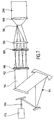
- a beam shaping lens 180 is provided, with which from the laser pulse 178 with a Gaussian beam profile a laser pulse 182 can be generated, which is essentially a rectangular jet profile or hat-top shaped jet profile of the laser pulse 182 can be generated.
- Such a beam shaping optics 180 is, for example, in FIG Fig. 7 shown as an example.
- the subrack 20 1 can again be moved to the next station, namely the coating station 28, by means of the overall control 130 and the control 120, in which, as shown in FIG. 8, a layer application, for example in the area 162 should take place.
- the entire assembly 40 is positioned exactly by means of a position marker 140 likewise provided on the coating station 28, with a correction also taking place simultaneously, according to the result of the calibration in the measuring station 24.
- a carrier 214 which has the layer segments 216 to be applied to the assembly 40, is provided above an outlet opening 210 for a laser radiation 212 of the coating station 28.
- the laser radiation preferably has 212 in the same way as the laser radiation 164 is a rectangular beam profile 182, that can be obtained by the beam shaping optics 180.
- assembly 40 for example either side of the measurement mark 148, to such an assembly 40 can be by the total controller 130 and 120 of the respective rack 20 1 carrying the control by moving the rack 20 1 to the mounting station 30, where, as in Figure 9, assembly 40 is possible on a basic assembly 220 provided in assembly station 30.
- the base assembly 220 also bears the position marker 140 and thus allows exact positioning of the gripper head 50 relative to this. Furthermore, the Basic assembly 220 on a positioning surface 222 of the Assembly station 30 that one with the transferred layer segment 216 layer element 224 to be joined by joining over an exit opening 226 for a joining laser beam 228 lies.
- module 40 By placing module 40 exactly on the Basic assembly 220 such that the layer segment 216 on the Layer element 224 rests, as shown in FIG. 9b, and Switching on the joining laser pulse 228 is a weld of the layer element 224 of the basic assembly 220 with the Layer segment 216 of assembly 40 possible and thus one Connection of the assembly 40 with the basic assembly 220, such as shown in Fig. 9b.
Landscapes
- Engineering & Computer Science (AREA)
- Mechanical Engineering (AREA)
- Laser Beam Processing (AREA)
Description
- Fig. 1
- eine Seitenansicht einer erfindungsgemäßen Einrichtung;
- Fig. 2
- eine vergrößerte schematische Darstellung eines Schnitts durch einen erfindungsgemäßen Greiferkopf;
- Fig. 3
- eine teilweise geschnittene Seitenansicht eines erfindungsgemäßen Baugruppenträgers;
- Fig. 4, umfassend Fig. 4a + 4b:
- einen Schnitt durch den Greiferkopf im Zusammenhang mit dem Aufnehmen einer Baugruppe in einer erfindungsgemäßen Aufnahmestation;
- Fig. 5
- einen Schnitt durch den Greiferkopf im Zusammenhang mit der Durchführung einer Feinpositionierung der Baugruppe in einer erfindungsgemäßen Meßstation;
- Fig. 6
- einen Schnitt durch den Greiferkopf im Zusammenhang mit der Durchführung eines Materialabtrags einer erfindungsgemäßen Abtragstation;
- Fig. 7
- eine schematische Darstellung einer erfindungsgemäßen Strahlformungsoptik;
- Fig. 8
- einen Schnitt durch den Greiferkopf im Zusammenhang mit der Darstellung einer Beschichtung der Baugruppe in einer erfindungsgemäßen Beschichtungsstation;
- Fig. 9, umfassend Fig. 9a - 9c
- einen Schnitt durch den Greiferkopf im Zusammenhang mit der Montage der erfindungsgemäßen Baugruppe auf einer Grundbaugruppe.
Claims (42)
- Verfahren zum Durchführen von Arbeitsschritten an miniaturisierten Baugruppen (40), die von einem mit einer Halteeinrichtung (50) versehenen Baugruppenträger (20) gehalten sind, in mindestens einer Arbeitsstation (22, 24, 26, 28, 30), wobei die Baugruppe (40) mit dem Baugruppenträger (20) zur Durchführung der Arbeitsschritte zu mehreren Arbeitsstationen (22, 24, 26, 28, 30) gebracht wird und durch Relativbewegung zwischen dem Baugruppenträger (20) und der jeweils einen der mehreren Arbeitsstationen (22, 24, 26, 28, 30) zum Durchführen eines der Arbeitsschritte exakt positioniert wird und wobei für die Durchführung der Arbeitsschritte die Positionierung der Baugruppe (40) gegenüber dem Baugruppenträger (20) aufrecht erhalten wird,
dadurch gekennzeichnet, daß eine Position der Baugruppe (40) relativ zum Baugruppenträger (20) durch eine am Baugruppenträger (20) angeordnete und eine Position der Baugruppe (40) erfassende Positioniereinrichtung (68) ermittelt wird und daß in einer Arbeitsstation (22, 24, 26, 28) eine gesteuerte Relativpositionierung zwischen Baugruppenträger (20) und Arbeitsstation (22, 24, 26, 28, 30), oder Baugruppenträger (20) und weiterer Baugruppe (220) oder Arbeitsstation (24) und Baugruppe (40) geführt durch an diesen angeordnete Positionserkennungselemente (98, 146, 140, 148, 58), durchgeführt wird. - Verfahren nach Anspruch 1, dadurch gekennzeichnet, daß bei Durchführung einer Folge von Arbeitsschritten die Baugruppe (40) stets von der Halteeinrichtung (50) des Baugruppenträgers (20) gehalten wird.
- Verfahren nach Anspruch 2, dadurch gekennzeichnet, daß die Folge von Arbeitsschritten mechanisch berührungslos durchgeführt wird.
- Verfahren nach Anspruch 3, dadurch gekennzeichnet, daß die Arbeitsschritte mittels elektromagnetischer Strahlung durchgeführt werden.
- Verfahren nach einem der voranstehenden Ansprüche, dadurch gekennzeichnet, daß als einer der Arbeitsschritte eine Feinpositionierung der Baugruppe (40) durchgeführt wird.
- Verfahren nach Anspruch 5, dadurch gekennzeichnet, daß beim Arbeitsschritt der Feinpositionierung eine exakte Position der Baugruppe (40) relativ zum Baugruppenträger (20) ermittelt und für nachfolgende Arbeitsschritte zur Verfügung gestellt wird.
- Verfahren nach einem der voranstehenden Ansprüche, dadurch gekennzeichnet, daß in einer der Arbeitsstationen ausschließlich berührungslose Arbeitsschritte durchgeführt werden.
- Verfahren nach Anspruch 7, dadurch gekennzeichnet, daß jeder berührungslose Arbeitsschritt mittels elektromagnetischer Strahlung durchgeführt wird.
- Verfahren nach Anspruch 8, dadurch gekennzeichnet, daß jeder Arbeitsschritt mit räumlich im wesentlichen gleichmäßiger Energiedichteverteilung durchgeführt wird.
- Verfahren nach Anspruch 8 oder 9, dadurch gekennzeichnet, daß jeder Arbeitsschritt mittels Laserstrahlung (164, 212) durchgeführt wird.
- Verfahren nach Anspruch 10, dadurch gekennzeichnet, daß ein Strahlprofil (182) des Laserstrahls (164, 212) rechteckig oder quadratisch ausgebildet ist.
- Verfahren nach Anspruch 10 oder 11, dadurch gekennzeichnet, daß jeder Arbeitsschritt mittels gepulster Laserstrahlung (164, 212) durchgeführt wird.
- Verfahren nach einem der voranstehenden Ansprüche, dadurch gekennzeichnet, daß in einer der Arbeitsstationen (28) ein Schichtauftrag auf die Baugruppe (40) mittels Laserstrahlung (212) durchgeführt wird.
- Verfahren nach einem der voranstehenden Ansprüche, dadurch gekennzeichnet, daß in einer der Arbeitsstationen (26) ein Materialabtrag von der Baugruppe (40) mittels Laserstrahlung (164) durchgeführt wird.
- Verfahren nach einem der voranstehenden Ansprüche, dadurch gekennzeichnet, daß in einer der Arbeitsstationen (30) eine Fügeverbindung auf der Baugruppe (40) mittels Energiezufuhr durch elektromagnetische Strahlung hergestellt wird.
- Verfahren nach einem der voranstehenden Ansprüche, dadurch gekennzeichnet, daß ein Baugruppenträger (20) entsprechend einer festgelegten Folge von einer Arbeitsstation (22, 24, 26, 28, 30) zur anderen bewegt wird.
- Verfahren nach Anspruch 16, dadurch gekennzeichnet, daß mehrere Baugruppenträger (20) gleichzeitig mit jeweils einer der mehreren Arbeitsstationen (22, 24, 26, 28, 30) zusammenwirken.
- Verfahren nach Anspruch 16 oder 17, dadurch gekennzeichnet, daß die Baugruppenträger (20) relativ zu einer Grundeinheit bewegt werden können.
- Verfahren nach Anspruch 18, dadurch gekennzeichnet, daß die Baugruppenträger (20) auf der Grundeinheit (18) entlang beliebig vorgebbarer Pfade bewegt werden können.
- Verfahren nach einem der voranstehenden Ansprüche, dadurch gekennzeichnet, daß die Baugruppenträger (20) berührungslos mit Steuerinformationen versorgt werden.
- Verfahren nach Anspruch 20, dadurch gekennzeichnet, daß die Baugruppenträger berührungslos positionsgesteuert werden.
- Verfahren nach einem der voranstehenden Ansprüche, dadurch gekennzeichnet, daß die Baugruppenträger (20) berührungslos mit Energie versorgt werden.
- Verfahren nach einem der voranstehenden Ansprüche, dadurch gekennzeichnet, daß die Baugruppenträger (20) Meßdaten berührungslos übermitteln.
- Einrichtung zum Durchführen von Arbeitsschritten an miniaturisierten Baugruppen, insbesondere nach einem der Ansprüche 1 bis 21, umfassend einen mit einer Halteeinrichtung (50) zum Halten der Baugruppen (40) versehenen Baugruppenträger (20) und mehrere Arbeitsstationen (22, 24, 26, 28, 30) zum Durchführen jeweils mindestens eines Arbeitsschritts, wobei der Baugruppenträger (20) so bewegbar ist, daß bei den mehreren Arbeitsstationen (22, 24, 26, 28, 30) die Baugruppe (40) zur Durchführung der Arbeitsschritte durch Relativbewegung zwischen Baugruppenträger (20) und Arbeitsstation (22, 24, 26, 28, 30) exakt positionierbar ist und die Baugruppe (40) mit der Halteeinrichtung (50) für die Durchführung der Arbeitsschritte in einer einzigen Relativposition zum Baugruppenträger (20) fixierbar ist, dadurch gekennzeichnet, daß eine Position der Baugruppe (40) relativ zum Baugruppenträger (20) durch eine am Baugruppenträger (20) angeordnete und eine Position der Baugruppe (40) erfassende Positioniereinrichtung (68) ermittelbar ist und daß in einer Arbeitsstation (22, 24, 26, 28) eine gesteuerte Relativpositionierung zwischen Baugruppenträger (20) und Arbeitsstation (22, 24, 26, 28, 30), oder Baugruppenträger (20) und weiterer Baugruppe (220) oder Arbeitsstation (24) und Baugruppe (40) geführt durch an diesen angeordnete Positionserkennungselemente (98, 146, 140, 148, 58), durchgeführbar ist.
- Einrichtung nach Anspruch 24, dadurch gekennzeichnet, daß die Baugruppe (40) an einem als Halteeinrichtung dienenden Greiferkopf (50) des Baugruppenträgers (20) fixierbar ist.
- Einrichtung nach Anspruch 25, dadurch gekennzeichnet, daß der Greiferkopf (50) einen Vakuumgreifer (53) für die Baugruppe (40) aufweist.
- Einrichtung nach Anspruch 26, dadurch gekennzeichnet, daß in dem Vakuumgreifer (53) eine Positioniereinrichtung (68) für die Baugruppe (40) integriert ist.
- Einrichtung nach Anspruch 27, dadurch gekennzeichnet, daß die Positioniereinrichtung (68) eine einer Vakuumkammer (56) des Vakuumgreifers (53) zugeordnete Markierung (72) auf der Baugruppe (40) erkennend ausgebildet ist.
- Einrichtung nach einem der Ansprüche 24 bis 28, dadurch gekennzeichnet, daß der Greiferkopf (50) und mindestens eine der Arbeitsstationen (24, 26, 28, 30) miteinander zusammenwirkende Positionserkennungselemente (90, 140) aufweisen, mit welchen der Greiferkopf (50) exakt zur Arbeitsstation (24, 26, 28, 30) positionierbar ist.
- Einrichtung nach einem der Ansprüche 24 bis 29, dadurch gekennzeichnet, daß der Baugruppenträger (20) eine Antriebseinheit (102) aufweist, mit welcher dieser relativ zu einer Grundeinheit (10) bewegbar ist.
- Einrichtung nach einem der Ansprüche 24 bis 30, dadurch gekennzeichnet, daß der Baugruppenträger (20) eine Koppeleinheit (104) aufweist, mit welcher Energie in den Baugruppenträger (20) einkoppelbar ist.
- Einrichtung nach einem der Ansprüche 24 bis 31, dadurch gekennzeichnet, daß der Baugruppenträger (20) Positioniereinheiten (108, 110, 112, 113, 114) aufweist, mit welchen der Greiferkopf (50) relativ zu einem Grundelement (46) des Baugruppenträgers (20) bewegbar ist.
- Einrichtung nach Anspruch 32, dadurch gekennzeichnet, daß der Baugruppenträger das Grundelement (46) und einen den Greiferkopf (50) tragenden Ausleger (44) aufweist.
- Einrichtung nach einem der Ansprüche 24 bis 33, dadurch gekennzeichnet, daß der Baugruppenträger (20) eine Steuerung (120) aufweist, mit welcher der Greiferkopf (50) positionierbar ist.
- Einrichtung nach Anspruch 34, dadurch gekennzeichnet, daß die Steuerung (120) mit einer Gesamtsteuerung (130) kommuniziert.
- Einrichtung nach Anspruch 35, dadurch gekennzeichnet, daß die Steuerung (120) mittels berührungsloser Informationsübertragung mit der Gesamtsteuerung (130) kommuniziert.
- Einrichtung nach einem der Ansprüche 24 bis 36, dadurch gekennzeichnet, daß eine der Arbeitsstationen (26, 28) mit einer Laserstrahlungsquelle (106) versehen ist, mit welcher die zur Durchführung des Arbeitsschritts in dieser erforderliche Laserstrahlung (164, 212) erzeugbar ist.
- Einrichtung nach Anspruch 37, dadurch gekennzeichnet, daß die Laserstrahlung aus einer einer in dieser Arbeitsstation (26, 28) positionierten Baugruppe (40) zugewandten Austrittsöffnung (160, 210) austritt.
- Einrichtung nach Anspruch 38, dadurch gekennzeichnet, daß in einer der Arbeitsstationen (28) zwischen der Austrittsöffnung (210) für die Laserstrahlung (212) und der Baugruppe (40) ein mit der Baugruppe (40) zu verbindendes Element (216) positionierbar ist.
- Einrichtung nach einem der Ansprüche 37 bis 39, dadurch gekennzeichnet, daß die Laserstrahlungsquelle (166) gepulste Laserstrahlung erzeugt.
- Einrichtung nach Anspruch 40, dadurch gekennzeichnet, daß die Laserstrahlungsquelle (166) Laserstrahlung (164, 212) mit Pulsdauern im Pikosekundenbereich erzeugt.
- Einrichtung nach Anspruch 40 oder 41 dadurch gekennzeichnet, daß die Laserstrahlungsquelle (166) Pulse mit einem rechteckigen Strahlprofil (182) erzeugt.
Applications Claiming Priority (3)
| Application Number | Priority Date | Filing Date | Title |
|---|---|---|---|
| DE19823196A DE19823196A1 (de) | 1998-05-23 | 1998-05-23 | Verfahren und Einrichtung zur Durchführung von Arbeitsschritten an miniaturisierten Baugruppen |
| DE19823196 | 1998-05-23 | ||
| PCT/EP1999/003465 WO1999061200A1 (de) | 1998-05-23 | 1999-05-20 | Verfahren und einrichtung zur durchführung von arbeitsschritten an miniaturisierten baugruppen |
Publications (2)
| Publication Number | Publication Date |
|---|---|
| EP1082193A1 EP1082193A1 (de) | 2001-03-14 |
| EP1082193B1 true EP1082193B1 (de) | 2003-10-01 |
Family
ID=7868776
Family Applications (1)
| Application Number | Title | Priority Date | Filing Date |
|---|---|---|---|
| EP99925016A Expired - Lifetime EP1082193B1 (de) | 1998-05-23 | 1999-05-20 | Verfahren und einrichtung zur durchführung von arbeitsschritten an miniaturisierten baugruppen |
Country Status (4)
| Country | Link |
|---|---|
| US (3) | US6596115B1 (de) |
| EP (1) | EP1082193B1 (de) |
| DE (2) | DE19823196A1 (de) |
| WO (1) | WO1999061200A1 (de) |
Families Citing this family (9)
| Publication number | Priority date | Publication date | Assignee | Title |
|---|---|---|---|---|
| DE19823196A1 (de) * | 1998-05-23 | 2000-01-13 | Deutsch Zentr Luft & Raumfahrt | Verfahren und Einrichtung zur Durchführung von Arbeitsschritten an miniaturisierten Baugruppen |
| DE19849658A1 (de) | 1998-10-29 | 2000-05-04 | Deutsch Zentr Luft & Raumfahrt | Verfahren und Einrichtung zum Ablösen eines Ausschnittes einer Materialschicht |
| US20100148813A1 (en) | 2006-07-18 | 2010-06-17 | Multiprobe, Inc. | Apparatus and method for combined micro-scale and nano-scale c-v, q-v, and i-v testing of semiconductor materials |
| US8800998B2 (en) * | 2011-12-30 | 2014-08-12 | Multiprobe, Inc. | Semiconductor wafer isolated transfer chuck |
| DE102013021716A1 (de) * | 2013-12-20 | 2015-06-25 | Gerresheimer Regensburg Gmbh | Vorrichtung und Verfahren zum Aufnehmen von Werkstücken |
| US10883168B2 (en) | 2014-09-11 | 2021-01-05 | Massachusetts Institute Of Technology | Processing system for small substrates |
| US9988216B1 (en) * | 2016-12-16 | 2018-06-05 | Amazon Technologies, Inc. | Parallel vertical recirculating gantry system |
| US10029865B1 (en) | 2016-12-16 | 2018-07-24 | Amazon Technologies, Inc. | Parallel recirculating gantry system on a rollercoaster-style track |
| KR102408524B1 (ko) * | 2017-09-19 | 2022-06-14 | 삼성디스플레이 주식회사 | 표시 장치의 제조 장치 및 표시 장치의 제조 방법 |
Family Cites Families (13)
| Publication number | Priority date | Publication date | Assignee | Title |
|---|---|---|---|---|
| US3901180A (en) * | 1974-01-16 | 1975-08-26 | Wheaton Industries | Apparatus for transfer and coating of bottles |
| US5672044A (en) * | 1974-01-24 | 1997-09-30 | Lemelson; Jerome H. | Free-traveling manipulator with powered tools |
| JPS57211430A (en) | 1981-06-16 | 1982-12-25 | Sony Corp | Method for supplying parts to automatic assembly machine and carrier for it |
| EP0360985B1 (de) * | 1988-06-29 | 1995-01-25 | Matsushita Electric Industrial Co., Ltd. | Elektronischen Bauelemente ergreifendes Gerät |
| US4946021A (en) * | 1988-10-17 | 1990-08-07 | Simplimatic Engineering Company | Multiple position, conveyor mountable workpiece carrier |
| JPH0828205B2 (ja) * | 1989-10-27 | 1996-03-21 | 株式会社日立製作所 | ウエハ搬送装置 |
| US5133444A (en) * | 1990-05-18 | 1992-07-28 | Juki America, Inc. | Method and apparatus for simultaneous transfer of workpieces between multiple stations |
| DK165055B (da) * | 1990-09-17 | 1992-10-05 | Rasmussen Th Molle & Maskin | Apparat med en sammenskydelig eller sammenklappelig faldskakt til udledning af risledygtigt styrtgods |
| US5332013A (en) * | 1991-03-15 | 1994-07-26 | Shinko Electric Co., Ltd. | Unmanned conveying device in clean room |
| DE4229399C2 (de) * | 1992-09-03 | 1999-05-27 | Deutsch Zentr Luft & Raumfahrt | Verfahren und Vorrichtung zum Herstellen einer Funktionsstruktur eines Halbleiterbauelements |
| US5377896A (en) * | 1993-11-12 | 1995-01-03 | At&T Corp. | Automatic mass handling system for small electronic components |
| DE19637822C1 (de) | 1996-09-17 | 1998-03-26 | Deutsch Zentr Luft & Raumfahrt | Mikromechanisches Werkzeug |
| DE19823196A1 (de) * | 1998-05-23 | 2000-01-13 | Deutsch Zentr Luft & Raumfahrt | Verfahren und Einrichtung zur Durchführung von Arbeitsschritten an miniaturisierten Baugruppen |
-
1998
- 1998-05-23 DE DE19823196A patent/DE19823196A1/de not_active Ceased
-
1999
- 1999-05-20 WO PCT/EP1999/003465 patent/WO1999061200A1/de not_active Ceased
- 1999-05-20 DE DE59907202T patent/DE59907202D1/de not_active Expired - Lifetime
- 1999-05-20 EP EP99925016A patent/EP1082193B1/de not_active Expired - Lifetime
-
2000
- 2000-11-21 US US09/718,229 patent/US6596115B1/en not_active Expired - Fee Related
-
2003
- 2003-07-15 US US10/620,861 patent/US20040026019A1/en not_active Abandoned
-
2005
- 2005-01-14 US US11/036,301 patent/US7165669B2/en not_active Expired - Fee Related
Also Published As
| Publication number | Publication date |
|---|---|
| WO1999061200A1 (de) | 1999-12-02 |
| DE19823196A1 (de) | 2000-01-13 |
| US20040026019A1 (en) | 2004-02-12 |
| US7165669B2 (en) | 2007-01-23 |
| DE59907202D1 (de) | 2003-11-06 |
| EP1082193A1 (de) | 2001-03-14 |
| US20050139449A1 (en) | 2005-06-30 |
| US6596115B1 (en) | 2003-07-22 |
Similar Documents
| Publication | Publication Date | Title |
|---|---|---|
| AT405775B (de) | Verfahren und vorrichtung zum ausgerichteten zusammenführen von scheibenförmigen halbleitersubstraten | |
| DE2834836C2 (de) | Vorrichtung zum Herstellen einer Hybrid-Leiterplatte durch Aufbringen elektronischer Bauelemente auf ein Substrat | |
| DE3429084C2 (de) | ||
| EP3596750B1 (de) | Verfahren zum bonden von mindestens drei substraten | |
| WO1985002088A1 (fr) | Procede et installation pour le positionnement de pieces detachees sur une piece a usiner | |
| EP0852556A1 (de) | Magazin für die fixierung von kleinteilen | |
| EP2126645B1 (de) | Verfahren zum kalibrieren der x-y positionierung eines positionierwerkzeugs, sowie vorrichtung mit einem derartigen positionierwerkzeug | |
| EP1082193B1 (de) | Verfahren und einrichtung zur durchführung von arbeitsschritten an miniaturisierten baugruppen | |
| CH698334A1 (de) | Verfahren für die Entnahme von Halbleiterchips von einem Wafertisch und Verfahren für die Montage von Halbleiterchips auf einem Substrat. | |
| DE102008013753A1 (de) | Probenverschiebungsverfahren in Ladungsteilchenstrahlgerät und Ladungsteilchenstrahlgerät sowie Probe für Transmissionselektronenmikroskop | |
| WO2017139825A1 (de) | Verfahren und vorrichtung zum fertigen von linsenpaketen | |
| EP0605679A1 (de) | Verfahren und vorrichtung zum stapeln von substraten, die durch bonden miteinander zu verbinden sind | |
| DE3340084C2 (de) | Vorrichtung zur Positionierung von Bauteilen auf einem Werkstück | |
| DE102008047575B4 (de) | Gerät zur Handhabung mindestens eines Objektträgers | |
| DE102009031233A1 (de) | Vorrichtung zur Strukturierung von Dünnschichtsolarzellenmodulen mittels Laser | |
| EP2012576A2 (de) | Bestückautomat und Verfahren zum Handhaben von Bauelementen | |
| DE19945648C2 (de) | Vorrichtung zum Be- und Entladen von Substraten | |
| EP1428060B1 (de) | Vorrichtung und verfahren zur planparallelen ausrichtung einer zu inspizierenden ebenen objektoberfläche zu einer fokusebene eines objektives | |
| DE102020108037B4 (de) | Positionierungseinrichtung und Verfahren zur Positionierung von Werkstücken | |
| EP4059654A1 (de) | Verfahren und fertigungssystem zur fertigung eines flachprodukts mit einer perforierten struktur, flachprodukt sowie verwendung des flachprodukts in einem mikrofilter | |
| DE2605940C3 (de) | Maskenjustier- und -belichtungsgerät | |
| EP1330152B1 (de) | Bestückkopf und Bestückverfahren zum Bestücken von Substraten mit Bauelementen | |
| DE10214550A1 (de) | Verfahren und Vorrichtung für den Transport von plattenförmigen Substraten von elektronischen Bauteilen und/oder Informationen | |
| EP1208584B1 (de) | Handhabungsvorrichtung zur bereitstellung eines wafer-stapels | |
| DE10109009C2 (de) | Bonder |
Legal Events
| Date | Code | Title | Description |
|---|---|---|---|
| PUAI | Public reference made under article 153(3) epc to a published international application that has entered the european phase |
Free format text: ORIGINAL CODE: 0009012 |
|
| 17P | Request for examination filed |
Effective date: 20001123 |
|
| AK | Designated contracting states |
Kind code of ref document: A1 Designated state(s): CH DE ES FI FR IT LI NL |
|
| 17Q | First examination report despatched |
Effective date: 20010309 |
|
| RAP1 | Party data changed (applicant data changed or rights of an application transferred) |
Owner name: MI LA SYS GBR |
|
| GRAH | Despatch of communication of intention to grant a patent |
Free format text: ORIGINAL CODE: EPIDOS IGRA |
|
| GRAS | Grant fee paid |
Free format text: ORIGINAL CODE: EPIDOSNIGR3 |
|
| GRAA | (expected) grant |
Free format text: ORIGINAL CODE: 0009210 |
|
| AK | Designated contracting states |
Kind code of ref document: B1 Designated state(s): CH DE ES FI FR IT LI NL |
|
| PG25 | Lapsed in a contracting state [announced via postgrant information from national office to epo] |
Ref country code: NL Free format text: LAPSE BECAUSE OF FAILURE TO SUBMIT A TRANSLATION OF THE DESCRIPTION OR TO PAY THE FEE WITHIN THE PRESCRIBED TIME-LIMIT Effective date: 20031001 Ref country code: FI Free format text: LAPSE BECAUSE OF FAILURE TO SUBMIT A TRANSLATION OF THE DESCRIPTION OR TO PAY THE FEE WITHIN THE PRESCRIBED TIME-LIMIT Effective date: 20031001 Ref country code: ES Free format text: LAPSE BECAUSE OF FAILURE TO SUBMIT A TRANSLATION OF THE DESCRIPTION OR TO PAY THE FEE WITHIN THE PRESCRIBED TIME-LIMIT Effective date: 20031001 |
|
| REG | Reference to a national code |
Ref country code: CH Ref legal event code: EP |
|
| REF | Corresponds to: |
Ref document number: 59907202 Country of ref document: DE Date of ref document: 20031106 Kind code of ref document: P |
|
| NLV1 | Nl: lapsed or annulled due to failure to fulfill the requirements of art. 29p and 29m of the patents act | ||
| PG25 | Lapsed in a contracting state [announced via postgrant information from national office to epo] |
Ref country code: LI Free format text: LAPSE BECAUSE OF NON-PAYMENT OF DUE FEES Effective date: 20040531 Ref country code: CH Free format text: LAPSE BECAUSE OF NON-PAYMENT OF DUE FEES Effective date: 20040531 |
|
| ET | Fr: translation filed | ||
| PLBE | No opposition filed within time limit |
Free format text: ORIGINAL CODE: 0009261 |
|
| STAA | Information on the status of an ep patent application or granted ep patent |
Free format text: STATUS: NO OPPOSITION FILED WITHIN TIME LIMIT |
|
| 26N | No opposition filed |
Effective date: 20040702 |
|
| REG | Reference to a national code |
Ref country code: CH Ref legal event code: PL |
|
| PGFP | Annual fee paid to national office [announced via postgrant information from national office to epo] |
Ref country code: IT Payment date: 20080510 Year of fee payment: 10 |
|
| PGFP | Annual fee paid to national office [announced via postgrant information from national office to epo] |
Ref country code: FR Payment date: 20080529 Year of fee payment: 10 |
|
| REG | Reference to a national code |
Ref country code: FR Ref legal event code: ST Effective date: 20100129 |
|
| PG25 | Lapsed in a contracting state [announced via postgrant information from national office to epo] |
Ref country code: FR Free format text: LAPSE BECAUSE OF NON-PAYMENT OF DUE FEES Effective date: 20090602 |
|
| PGFP | Annual fee paid to national office [announced via postgrant information from national office to epo] |
Ref country code: DE Payment date: 20100624 Year of fee payment: 12 |
|
| PG25 | Lapsed in a contracting state [announced via postgrant information from national office to epo] |
Ref country code: IT Free format text: LAPSE BECAUSE OF NON-PAYMENT OF DUE FEES Effective date: 20090520 |
|
| REG | Reference to a national code |
Ref country code: DE Ref legal event code: R119 Ref document number: 59907202 Country of ref document: DE |
|
| REG | Reference to a national code |
Ref country code: DE Ref legal event code: R119 Ref document number: 59907202 Country of ref document: DE |
|
| PG25 | Lapsed in a contracting state [announced via postgrant information from national office to epo] |
Ref country code: DE Free format text: LAPSE BECAUSE OF NON-PAYMENT OF DUE FEES Effective date: 20111130 |