EP1082231B1 - Procede et dispositif pour piloter une machine motrice - Google Patents
Procede et dispositif pour piloter une machine motrice Download PDFInfo
- Publication number
- EP1082231B1 EP1082231B1 EP99932618A EP99932618A EP1082231B1 EP 1082231 B1 EP1082231 B1 EP 1082231B1 EP 99932618 A EP99932618 A EP 99932618A EP 99932618 A EP99932618 A EP 99932618A EP 1082231 B1 EP1082231 B1 EP 1082231B1
- Authority
- EP
- European Patent Office
- Prior art keywords
- torque
- tqi
- internal combustion
- combustion engine
- value
- Prior art date
- Legal status (The legal status is an assumption and is not a legal conclusion. Google has not performed a legal analysis and makes no representation as to the accuracy of the status listed.)
- Expired - Lifetime
Links
Images



Classifications
-
- B—PERFORMING OPERATIONS; TRANSPORTING
- B60—VEHICLES IN GENERAL
- B60K—ARRANGEMENT OR MOUNTING OF PROPULSION UNITS OR OF TRANSMISSIONS IN VEHICLES; ARRANGEMENT OR MOUNTING OF PLURAL DIVERSE PRIME-MOVERS IN VEHICLES; AUXILIARY DRIVES FOR VEHICLES; INSTRUMENTATION OR DASHBOARDS FOR VEHICLES; ARRANGEMENTS IN CONNECTION WITH COOLING, AIR INTAKE, GAS EXHAUST OR FUEL SUPPLY OF PROPULSION UNITS IN VEHICLES
- B60K6/00—Arrangement or mounting of plural diverse prime-movers for mutual or common propulsion, e.g. hybrid propulsion systems comprising electric motors and internal combustion engines
- B60K6/20—Arrangement or mounting of plural diverse prime-movers for mutual or common propulsion, e.g. hybrid propulsion systems comprising electric motors and internal combustion engines the prime-movers consisting of electric motors and internal combustion engines, e.g. HEVs
- B60K6/42—Arrangement or mounting of plural diverse prime-movers for mutual or common propulsion, e.g. hybrid propulsion systems comprising electric motors and internal combustion engines the prime-movers consisting of electric motors and internal combustion engines, e.g. HEVs characterised by the architecture of the hybrid electric vehicle
- B60K6/48—Parallel type
- B60K6/485—Motor-assist type
-
- B—PERFORMING OPERATIONS; TRANSPORTING
- B60—VEHICLES IN GENERAL
- B60W—CONJOINT CONTROL OF VEHICLE SUB-UNITS OF DIFFERENT TYPE OR DIFFERENT FUNCTION; CONTROL SYSTEMS SPECIALLY ADAPTED FOR HYBRID VEHICLES; ROAD VEHICLE DRIVE CONTROL SYSTEMS FOR PURPOSES NOT RELATED TO THE CONTROL OF A PARTICULAR SUB-UNIT
- B60W20/00—Control systems specially adapted for hybrid vehicles
- B60W20/40—Controlling the engagement or disengagement of prime movers, e.g. for transition between prime movers
-
- B—PERFORMING OPERATIONS; TRANSPORTING
- B60—VEHICLES IN GENERAL
- B60W—CONJOINT CONTROL OF VEHICLE SUB-UNITS OF DIFFERENT TYPE OR DIFFERENT FUNCTION; CONTROL SYSTEMS SPECIALLY ADAPTED FOR HYBRID VEHICLES; ROAD VEHICLE DRIVE CONTROL SYSTEMS FOR PURPOSES NOT RELATED TO THE CONTROL OF A PARTICULAR SUB-UNIT
- B60W10/00—Conjoint control of vehicle sub-units of different type or different function
- B60W10/04—Conjoint control of vehicle sub-units of different type or different function including control of propulsion units
- B60W10/06—Conjoint control of vehicle sub-units of different type or different function including control of propulsion units including control of combustion engines
-
- B—PERFORMING OPERATIONS; TRANSPORTING
- B60—VEHICLES IN GENERAL
- B60W—CONJOINT CONTROL OF VEHICLE SUB-UNITS OF DIFFERENT TYPE OR DIFFERENT FUNCTION; CONTROL SYSTEMS SPECIALLY ADAPTED FOR HYBRID VEHICLES; ROAD VEHICLE DRIVE CONTROL SYSTEMS FOR PURPOSES NOT RELATED TO THE CONTROL OF A PARTICULAR SUB-UNIT
- B60W10/00—Conjoint control of vehicle sub-units of different type or different function
- B60W10/04—Conjoint control of vehicle sub-units of different type or different function including control of propulsion units
- B60W10/08—Conjoint control of vehicle sub-units of different type or different function including control of propulsion units including control of electric propulsion units, e.g. motors or generators
-
- B—PERFORMING OPERATIONS; TRANSPORTING
- B60—VEHICLES IN GENERAL
- B60W—CONJOINT CONTROL OF VEHICLE SUB-UNITS OF DIFFERENT TYPE OR DIFFERENT FUNCTION; CONTROL SYSTEMS SPECIALLY ADAPTED FOR HYBRID VEHICLES; ROAD VEHICLE DRIVE CONTROL SYSTEMS FOR PURPOSES NOT RELATED TO THE CONTROL OF A PARTICULAR SUB-UNIT
- B60W20/00—Control systems specially adapted for hybrid vehicles
-
- F—MECHANICAL ENGINEERING; LIGHTING; HEATING; WEAPONS; BLASTING
- F02—COMBUSTION ENGINES; HOT-GAS OR COMBUSTION-PRODUCT ENGINE PLANTS
- F02D—CONTROLLING COMBUSTION ENGINES
- F02D41/00—Electrical control of supply of combustible mixture or its constituents
- F02D41/24—Electrical control of supply of combustible mixture or its constituents characterised by the use of digital means
- F02D41/26—Electrical control of supply of combustible mixture or its constituents characterised by the use of digital means using computer, e.g. microprocessor
- F02D41/28—Interface circuits
-
- B—PERFORMING OPERATIONS; TRANSPORTING
- B60—VEHICLES IN GENERAL
- B60L—PROPULSION OF ELECTRICALLY-PROPELLED VEHICLES; SUPPLYING ELECTRIC POWER FOR AUXILIARY EQUIPMENT OF ELECTRICALLY-PROPELLED VEHICLES; ELECTRODYNAMIC BRAKE SYSTEMS FOR VEHICLES IN GENERAL; MAGNETIC SUSPENSION OR LEVITATION FOR VEHICLES; MONITORING OPERATING VARIABLES OF ELECTRICALLY-PROPELLED VEHICLES; ELECTRIC SAFETY DEVICES FOR ELECTRICALLY-PROPELLED VEHICLES
- B60L2240/00—Control parameters of input or output; Target parameters
- B60L2240/40—Drive Train control parameters
- B60L2240/42—Drive Train control parameters related to electric machines
- B60L2240/423—Torque
-
- B—PERFORMING OPERATIONS; TRANSPORTING
- B60—VEHICLES IN GENERAL
- B60W—CONJOINT CONTROL OF VEHICLE SUB-UNITS OF DIFFERENT TYPE OR DIFFERENT FUNCTION; CONTROL SYSTEMS SPECIALLY ADAPTED FOR HYBRID VEHICLES; ROAD VEHICLE DRIVE CONTROL SYSTEMS FOR PURPOSES NOT RELATED TO THE CONTROL OF A PARTICULAR SUB-UNIT
- B60W50/00—Details of control systems for road vehicle drive control not related to the control of a particular sub-unit, e.g. process diagnostic or vehicle driver interfaces
- B60W2050/0001—Details of the control system
- B60W2050/0019—Control system elements or transfer functions
- B60W2050/0042—Transfer function lag; delays
-
- B—PERFORMING OPERATIONS; TRANSPORTING
- B60—VEHICLES IN GENERAL
- B60W—CONJOINT CONTROL OF VEHICLE SUB-UNITS OF DIFFERENT TYPE OR DIFFERENT FUNCTION; CONTROL SYSTEMS SPECIALLY ADAPTED FOR HYBRID VEHICLES; ROAD VEHICLE DRIVE CONTROL SYSTEMS FOR PURPOSES NOT RELATED TO THE CONTROL OF A PARTICULAR SUB-UNIT
- B60W50/00—Details of control systems for road vehicle drive control not related to the control of a particular sub-unit, e.g. process diagnostic or vehicle driver interfaces
- B60W2050/0001—Details of the control system
- B60W2050/0043—Signal treatments, identification of variables or parameters, parameter estimation or state estimation
- B60W2050/0052—Filtering, filters
-
- B—PERFORMING OPERATIONS; TRANSPORTING
- B60—VEHICLES IN GENERAL
- B60W—CONJOINT CONTROL OF VEHICLE SUB-UNITS OF DIFFERENT TYPE OR DIFFERENT FUNCTION; CONTROL SYSTEMS SPECIALLY ADAPTED FOR HYBRID VEHICLES; ROAD VEHICLE DRIVE CONTROL SYSTEMS FOR PURPOSES NOT RELATED TO THE CONTROL OF A PARTICULAR SUB-UNIT
- B60W2510/00—Input parameters relating to a particular sub-units
- B60W2510/06—Combustion engines, Gas turbines
- B60W2510/0614—Position of fuel or air injector
- B60W2510/0628—Inlet air flow rate
-
- B—PERFORMING OPERATIONS; TRANSPORTING
- B60—VEHICLES IN GENERAL
- B60W—CONJOINT CONTROL OF VEHICLE SUB-UNITS OF DIFFERENT TYPE OR DIFFERENT FUNCTION; CONTROL SYSTEMS SPECIALLY ADAPTED FOR HYBRID VEHICLES; ROAD VEHICLE DRIVE CONTROL SYSTEMS FOR PURPOSES NOT RELATED TO THE CONTROL OF A PARTICULAR SUB-UNIT
- B60W2710/00—Output or target parameters relating to a particular sub-units
- B60W2710/06—Combustion engines, Gas turbines
- B60W2710/0616—Position of fuel or air injector
-
- B—PERFORMING OPERATIONS; TRANSPORTING
- B60—VEHICLES IN GENERAL
- B60W—CONJOINT CONTROL OF VEHICLE SUB-UNITS OF DIFFERENT TYPE OR DIFFERENT FUNCTION; CONTROL SYSTEMS SPECIALLY ADAPTED FOR HYBRID VEHICLES; ROAD VEHICLE DRIVE CONTROL SYSTEMS FOR PURPOSES NOT RELATED TO THE CONTROL OF A PARTICULAR SUB-UNIT
- B60W2710/00—Output or target parameters relating to a particular sub-units
- B60W2710/06—Combustion engines, Gas turbines
- B60W2710/0666—Engine torque
-
- B—PERFORMING OPERATIONS; TRANSPORTING
- B60—VEHICLES IN GENERAL
- B60W—CONJOINT CONTROL OF VEHICLE SUB-UNITS OF DIFFERENT TYPE OR DIFFERENT FUNCTION; CONTROL SYSTEMS SPECIALLY ADAPTED FOR HYBRID VEHICLES; ROAD VEHICLE DRIVE CONTROL SYSTEMS FOR PURPOSES NOT RELATED TO THE CONTROL OF A PARTICULAR SUB-UNIT
- B60W2710/00—Output or target parameters relating to a particular sub-units
- B60W2710/08—Electric propulsion units
- B60W2710/083—Torque
-
- F—MECHANICAL ENGINEERING; LIGHTING; HEATING; WEAPONS; BLASTING
- F02—COMBUSTION ENGINES; HOT-GAS OR COMBUSTION-PRODUCT ENGINE PLANTS
- F02D—CONTROLLING COMBUSTION ENGINES
- F02D2200/00—Input parameters for engine control
- F02D2200/02—Input parameters for engine control the parameters being related to the engine
- F02D2200/10—Parameters related to the engine output, e.g. engine torque or engine speed
- F02D2200/1006—Engine torque losses, e.g. friction or pumping losses or losses caused by external loads of accessories
-
- Y—GENERAL TAGGING OF NEW TECHNOLOGICAL DEVELOPMENTS; GENERAL TAGGING OF CROSS-SECTIONAL TECHNOLOGIES SPANNING OVER SEVERAL SECTIONS OF THE IPC; TECHNICAL SUBJECTS COVERED BY FORMER USPC CROSS-REFERENCE ART COLLECTIONS [XRACs] AND DIGESTS
- Y02—TECHNOLOGIES OR APPLICATIONS FOR MITIGATION OR ADAPTATION AGAINST CLIMATE CHANGE
- Y02T—CLIMATE CHANGE MITIGATION TECHNOLOGIES RELATED TO TRANSPORTATION
- Y02T10/00—Road transport of goods or passengers
- Y02T10/10—Internal combustion engine [ICE] based vehicles
- Y02T10/40—Engine management systems
-
- Y—GENERAL TAGGING OF NEW TECHNOLOGICAL DEVELOPMENTS; GENERAL TAGGING OF CROSS-SECTIONAL TECHNOLOGIES SPANNING OVER SEVERAL SECTIONS OF THE IPC; TECHNICAL SUBJECTS COVERED BY FORMER USPC CROSS-REFERENCE ART COLLECTIONS [XRACs] AND DIGESTS
- Y02—TECHNOLOGIES OR APPLICATIONS FOR MITIGATION OR ADAPTATION AGAINST CLIMATE CHANGE
- Y02T—CLIMATE CHANGE MITIGATION TECHNOLOGIES RELATED TO TRANSPORTATION
- Y02T10/00—Road transport of goods or passengers
- Y02T10/60—Other road transportation technologies with climate change mitigation effect
- Y02T10/62—Hybrid vehicles
-
- Y—GENERAL TAGGING OF NEW TECHNOLOGICAL DEVELOPMENTS; GENERAL TAGGING OF CROSS-SECTIONAL TECHNOLOGIES SPANNING OVER SEVERAL SECTIONS OF THE IPC; TECHNICAL SUBJECTS COVERED BY FORMER USPC CROSS-REFERENCE ART COLLECTIONS [XRACs] AND DIGESTS
- Y02—TECHNOLOGIES OR APPLICATIONS FOR MITIGATION OR ADAPTATION AGAINST CLIMATE CHANGE
- Y02T—CLIMATE CHANGE MITIGATION TECHNOLOGIES RELATED TO TRANSPORTATION
- Y02T10/00—Road transport of goods or passengers
- Y02T10/60—Other road transportation technologies with climate change mitigation effect
- Y02T10/64—Electric machine technologies in electromobility
Definitions
- the invention relates to a method according to the preamble of claim 1 and a device according to the preamble of claim 9.
- a method for controlling an internal combustion engine is off known from DE 196 12 455 A1.
- a setpoint of a torque becomes dependent on the accelerator pedal position of an accelerator pedal, the Speed and other operating parameters such as air mass flow, the coolant temperature and the oil temperature.
- Dependent a control signal for a Throttle valve actuator determined. That about the air mass flow
- the torque to be set is determined taking into account of the target torque and lead values of Torque by functions to control the internal combustion engine, such as traction control, speed limitation, a speed limit and a catalyst heating function, be requested.
- There is also a setpoint of the torque that can be set quickly from the target torque and torque requirements of the others Functions for controlling the internal combustion engine.
- An actuating signal for a spark plug depends on the setpoint of the Torque.
- crankshaft segment By changing the ignition angle can be within of a crankshaft segment that is actually in a cylinder the torque generated by the internal combustion engine is changed become.
- the duration of a crankshaft segment is, for example by the time interval between the ignitions of two defined in the firing order of adjacent cylinders.
- the setpoint of the Torque to be set via the air mass flow only be adjusted slowly. Does that actually tell of the Torque to be generated by the internal combustion engine is highly dynamic on, the lead values must be chosen large in order to Set torque with high quality. However, this has high Exhaust emissions from the internal combustion engine and a high Result in fuel consumption.
- JP-A-09084211 is another method for controlling one An engine comprising an internal combustion engine.
- a setpoint of a torque is dependent of a size and representing the driver's request
- Operating variables of the internal combustion engine determined.
- control signals for actuators of the internal combustion engine are determined dependent from the setpoint of the torque.
- An estimate of one maximum torque is determined using the actuators the internal combustion engine within a predetermined Time is adjustable. The determination of this estimate is done by adding a torque increase value per predetermined period of time at which in a previous calculation cycle set old torque value.
- On Control signal for a motor generator is then dependent on the target value and the estimated value of the maximum torque.
- the object of the invention is a device and a To provide methods of controlling an engine which is comfortable and low in emissions Operation of the internal combustion engine with high efficiency the engine is guaranteed and precise.
- the object is achieved through the features of the independent claims solved.
- the invention is characterized in that that a control signal for a motor generator that is on the drive shaft the internal combustion engine is arranged, depending is determined from the nominal value of the torque.
- the engine generator has a response time that is significantly lower than the length of time until a jump in the setpoint torque is set via the air mass flow. So they can Reserve values for the one to be set via the air mass flow Torque can be selected lower without sacrificing comfort to have to put up with.
- the invention is further characterized in that the Control signal for that designed as a spark plug or injection valve Actuator depends on a setpoint of the torque and the estimate of the actual motor generator Torque. This is an extremely precise adjustment of the Torque setpoint enabled.
- An engine ( Figure 1) includes an internal combustion engine.
- the internal combustion engine has an intake tract 1 with a Throttle valve 10 and an engine block 2, which is a cylinder 20 and a crankshaft 23.
- a piston 21 and one Connecting rod 22 are assigned to cylinder 20.
- the connecting rod 22 is connected to the piston 21 and the crankshaft 23.
- a cylinder head 3 is provided in which a valve train is arranged is with at least one inlet valve 30, an outlet valve 31 and one each assigned to the inlet valve 30 Valve drive 32a and one associated with the exhaust valve 31 Valve actuator 32b.
- An injection valve 11 is introduced into the intake tract 1, which is arranged so that the fuel in the intake tract 1 is measured.
- the injection valve 11 can alternatively also be introduced into the cylinder head 3 and arranged there be that the fuel directly into the interior of the Cylinder 20 is metered.
- a spark plug 34 is in a Recess of the cylinder head 3 introduced.
- the internal combustion engine is shown in Figure 1 with a cylinder. However, it can also comprise several cylinders.
- An exhaust tract 4 is assigned to the internal combustion engine.
- Motor-generator 5 is provided, the rotor of which is non-positive is connected to the crankshaft 23.
- the engine generator is preferably designed as an asynchronous machine. However, he can also as a synchronous machine or as a DC motor be trained.
- the crankshaft 23 is the in engine operation Output shaft of the motor generator and in generator operation the drive shaft of the motor generator.
- the motor generator 5 replaces the starter and the usual generator one Internal combustion engine. The engine is therefore essential compact.
- the crankshaft 23 is not connected to a clutch 6 shown transmission can be coupled. If the transmission as an automatic transmission is formed, then the clutch 6 is for example preferably as a lockup clutch a hydrodynamic converter.
- a control device 7 for the engine is provided, the sensors are assigned to the various measured variables record and determine the measured value of the measured variable.
- the Control device 7 determines depending on at least one Operating variable one or more control signals that an actuator Taxes.
- the sensors are a pedal position sensor 81, which is a pedal position PV of the accelerator pedal 8 detects a throttle position transmitter 12, which detects an opening degree of the throttle valve, an air mass meter 13 which detects an air mass flow and / or an intake manifold pressure sensor 14, which is an intake manifold pressure detected in the intake tract 1, a first temperature sensor 15 which detects an intake air temperature, a speed sensor 24, which detects a rotational speed N of the crankshaft 23, and a second and third temperature sensor 26, 27, which is an oil temperature TOIL or a coolant temperature TCO to capture. Furthermore, a measuring unit 51 is provided which characteristic operating variable of the motor generator 5 detected. The characteristic operating size of the motor generator 5 can be, for example, a current or a voltage or be an achievement.
- the control device 7 can any subset of the sensors mentioned can be assigned, additional sensors can also be assigned here his.
- Operating variables include measured variables and those derived from them Sizes that are related to or from a map Observers are determined, the estimates of the farm sizes calculated.
- the actuators each include an actuator and a Actuator.
- the actuator is an electric motor drive, an electromagnetic drive, a mechanical one or another drive known to the person skilled in the art.
- the actuators are as a throttle valve 10, as an injection valve 11, as a spark plug 34 or as another to the specialist in internal combustion engines known actuators trained.
- On the Actuators are assigned below with the respectively Actuator referred.
- the control device is preferably an electronic engine control educated. However, it can also have several control units include the electrically connected together are, e.g. with a bus system.
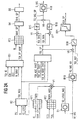
- a map KF1 is provided, from which a first contribution TQFR to a loss torque TQ_LOSS depending on the Speed N, and the estimated value MAF_CYL of the air mass flow is determined in the cylinder 20.
- the first contribution to the TQFR Loss torque TQ_LOSS takes pump losses into account Internal combustion engine and losses caused by friction at given Reference values of the coolant temperature TCO and the Oil temperature TOIL occur.
- a second contribution TQFR_ADD to the loss torque TQ_LOSS is determined from a map KF2 depending on the oil temperature TOIL and / or the coolant temperature TCO. Furthermore, a third contribution TQ_LOSS_MG to the loss torque is determined as a function of the measurement signal M_MG that is generated by the measurement unit 51. The third contribution TQ_LOSS_MG to the loss torque TQ_LOSS is determined in a block B1 using a dynamic model of the losses of the motor generator.
- the dynamic model of the losses of the motor generator 5 preferably comprises a characteristic curve in which the characteristic values of the third contribution TQ_LOSS_MG are stored as a function of a detected current through the motor generator 5.
- the characteristic values are corrected with a correction factor which depends on the temperature of the motor generator, this correction factor preferably being subjected to PD 1 filtering.
- the temperature of the motor generator is either determined directly or determined from a map depending on the power supplied or removed by the motor generator.
- the intake temperature is also taken into account when correcting the third contribution TQ_LOSS_MG to the loss torque TQ_LOSS.
- the contributions TQFR, TQFR_ADD, TQ_LOSS_MG are added in a node V1. Their sum then forms the loss torque TQ_LOSS.
- block B2 there is an available torque range depending on the loss torque TQ_LOSS and the speed N determined. From the accelerator pedal position PV and the speed N is determined, what proportion of the available adjustable torque range requested by the driver becomes. From the requested portion of the torque and the The torque that can be made available is then a driver's request corresponding value TQI_REQ of the torque is determined. Filtering of the driver's request is also preferred corresponding value TQI_REQ of the torque is provided, to ensure that no load jumps can occur, which lead to an uncomfortable jerking of the vehicle, in which the engine is arranged.
- a setpoint TQI_SP_MAF of the Determined air mass flow torque there in addition to the value TQI_REQ of the torque, lead values considered. For example, a lead value TQI_IS specified by an idle controller, a lead value TQI_CH of a function for heating a catalytic converter specified, a lead value TQI_ASC from an anti-slip control specified, a lead value TQI_N_MAX of a function for speed limitation, or a Lead value TQI_MSR from a motor drag torque control specified.
- the setpoint TQI_SP_MAF of the air mass flow Torque to be set can thus be greater or be less than the value TQI_REQ of the torque corresponding to the Driver request corresponds.
- the setpoint TQI_SP_MAF of the is via a map KF3 the air mass flow to be set depending on a nominal value MAF_SP of the air mass flow is assigned to the speed N.
- the values of the map KF3 are from measurements on one Engine test bench with a reference air ratio LAM_REF and at a reference ignition angle IGA_REF derived or by a simulation calculation is determined.
- a control signal is generated in a block B5 determined to control the throttle valve 10, preferably from a position controller of the throttle valve 10.
- the setpoint TQI_SP_MAF to be set via the air mass flow Torque anticipates this under taking into account the dynamics of the intake tract Torque.
- a setpoint TQI_SP of the torque determined to set within a predetermined period of time is.
- the predetermined time period preferably corresponds the length of time determined by a crankshaft segment is.
- a crankshaft segment is determined by the angle between two top dead centers of two neighboring in the firing order Cylinder or even by the ignition interval of two in the firing order of neighboring cylinders.
- the setpoint TQI_SP of the Torque must therefore be very fast, e.g. within a Working cycle of the internal combustion engine to be adjustable.
- the setpoint TQI_SP of the torque depending on the value TQI_REQ corresponding to the driver's request of the torque and torque requirements TQI_ASC_FAST, TQI_GS_FAST, TQI_N_MAX_FAST an anti-slip control, one Transmission control and a function to limit the speed N calculated.
- other torque requirements can also be met be taken into account.
- a map KF4 is provided, from which depends from the estimated value MAF_CYL and the speed N a reference value TQI_REF of the torque is determined.
- the values of Kennfelds KF4 are from measurements on an engine test bench a reference air ratio LAM_REF and at a reference ignition angle IGA_REF derived or by a simulation calculation determined.
- the reference value TQI_REF of the torque is therefore always the torque that the corresponding Speed and the corresponding air mass flow in the Cylinder can theoretically be realized at maximum if at the same time the efficiency EFF_IGA related to the ignition angle and the efficiency EFF_LAM based on the air ratio are maximum.
- the reference ignition angle IGA_REF is shown in a map KF5 depending on the speed, the estimated value MAF_CYL of the air mass flow in the cylinder 20 and the coolant temperature TCO determined.
- the efficiency EFF_IGA of the ignition angle is standardized to the Efficiency of the ignition angle at the reference ignition angle IGA_REF.
- the reference air ratio LAM_REF is dependent on a map KF7 of the speed N and the estimated value MAF_CYL des Air mass flow in the cylinder 20 is determined.
- a pareto optimal The basic air ratio LAM_BAS is converted from a map KF8 depending on the speed N and an estimate MAF_CYL des Air mass flow in the cylinder 20 is determined.
- In a tie point V3 becomes the difference in the basic air ratio LAM_BAS and the reference air ratio LAM_REF formed and then the efficiency EFF_LAM of the air ratio is standardized in block B9 determined on the efficiency at the reference air ratio LAM_REF.
- the estimated value TQI_BAS is the maximum Torque from the product of the reference value TQI_REF des Torque of the efficiency EFF_IGA of the ignition angle and of the EFF_LAM efficiency of the air ratio.
- the Estimated value TQI_BAS of the maximum torque is therefore the highest value of the torque actually at a given MAF_CYL estimate of the air mass flow into the cylinder 20, the speed N and the coolant temperature through the Internal combustion engine can be applied.
- the underlying TQI_BAS of the torque is therefore always less than or equal to the reference value TQI_REF of the torque.
- a minimum air ratio is shown in a map KF11 LAM_MIN depending on the speed and the estimated value MAF_CYL of the air mass flow in the cylinder 20 a minimum air ratio LAM_MIN determined.
- LAM_MIN the Difference between the minimum air ratio LAM_MIN and the reference air ratio LAM_REF formed.
- EFF_SCC Cylinder deactivation efficiency depending on the Number of shutdowns in the overrun mode of the internal combustion engine Cylinder determined.
- the minimum torque estimate TQI_MIN is then in block B13 by forming the product of the reference value the torque TQI_REF, the efficiency EFF_IGA, the ignition angle, the efficiency EFF_LAM, the air ratio and the efficiency EFF_SCC of cylinder deactivation determined.
- the estimated value TQI_MIN of the minimum torque is therefore the lowest value of the torque that is actually at one given estimate MAF_CYL of the air mass flow into the cylinder 20, the speed N and the coolant temperature the internal combustion engine can be applied.
- connection point V6 Figure 2a
- one block B15 will lower this difference to a predetermined one Threshold limited.
- the lower threshold can be special simply be chosen to be zero. It can also be smaller Be selected zero or depending on the temperature of the motor generator or the degree of loading of a voltage supply (Battery) of the vehicle in which the engine is arranged to be determined. This can be done in a simple way the availability of the motor generator, d. H. the time between two failures of the motor generator are increased.
- the state of charge of the battery can also be set to a predetermined level advantageous value can be kept.
- the difference in the setpoint is shown in a node V7 TQI_SP of the torque and the estimated value TQI_MIN of the minimum torque is formed.
- a block B16 then limiting this difference to an upper threshold which is either the fixed value zero or one has a predetermined value greater than zero or has a value which depends on the temperature of the motor generator 5 or the degree of charge of the battery.
- the physical model comprises, for example, a characteristic curve from which the control signal S_MG of the motor generator is determined depending on the setpoint TQ_MG_SP of the torque to be applied by the motor generator 5.
- the control signal S_MG of the motor generator 5 is then multiplicatively corrected depending on a correction value.
- the correction value is determined from a characteristic diagram as a function of the temperature of the motor generator 5 and the speed N and is then subjected to PD 1 filtering.
- a model describes the dynamic behavior of the motor generator with sufficient accuracy.
- the motor generator 5 is controlled with the control signal S_MG.
- the control signal S_MG can either be a current through the Windings of the motor generator 5 or a voltage.
- the decisive signal parameter is either the amplitude or the frequency of the voltage or current.
- an estimate TQ_MG_AV of the by Motor-generator 5 applied torque to the inverse physical model described in block B18 of the motor generator determined.
- the determination is made of the estimated value TQ_MG_AV of that applied by the motor generator Torque depending on the measurement signal M_MG of the Motor generator, for example the voltage or the Current through the motor generator 5 is.
- the difference in the setpoint is shown in a node V8 TQI_SP of the torque and the estimated value TQ_MG_AV of the torque actually applied by the motor generator determined.
- the determined in node V8 Difference therefore represents the proportion of the setpoint TQI_SP Torque represents that is not applied by the motor generator 5 becomes.
- a block B20 the quotient that is in the node V8 determined difference and the reference value TQI_REF of the torque determined.
- the quotient is then the input variable a characteristic curve in a block B21, from which a Setpoint IGA_SP of the ignition angle is determined.
- the spark plug 34 is then corresponding to the setpoint IGA_SP of the ignition angle driven.
- the control device 7 is characterized in that the Reserve values TQI_IS, TQI_CH, TQI_ASC and TQI_N_MAX low can be chosen because of an actual requirement of this torque, i.e. with a high dynamic of the setpoint TQI_SP quick adjustment via the motor generator 5 can take place, its response time is essential is less than the response time of the intake tract to changes the throttle position.
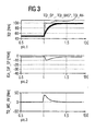
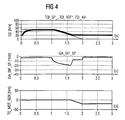
- 3 and 4 are time profiles of the setpoint TQI_SP of the torque with a positive jump in the setpoint TQI_SP, the estimated value TQI_BAS of the maximum torque and an estimate of one actually in the internal combustion engine realized torque, the difference of the reference ignition angle IGA_REF and the setpoint IGA_SP of the Ignition angle and the estimated value TQI_MG_AV of the actual torque applied by the motor generator 5 represented over time t.
- the estimated value TQI_MIN in FIG. 3 the value 20 Nm.
Landscapes
- Engineering & Computer Science (AREA)
- Chemical & Material Sciences (AREA)
- Combustion & Propulsion (AREA)
- Mechanical Engineering (AREA)
- Transportation (AREA)
- Automation & Control Theory (AREA)
- Computer Hardware Design (AREA)
- Microelectronics & Electronic Packaging (AREA)
- General Engineering & Computer Science (AREA)
- Combined Controls Of Internal Combustion Engines (AREA)
- Hybrid Electric Vehicles (AREA)
- Control Of Vehicle Engines Or Engines For Specific Uses (AREA)
Abstract
Claims (7)
- Procédé permettant de commander une machine motrice comprenant un moteur à combustion interne, dans lequelcaractérisé en ce queune valeur de consigne (TQI_SP) d'un couple dépend d'une grandeur représentant la sollicitation du conducteur et des grandeurs de fonctionnement du moteur à combustion interne,des signaux de commande destinés à des organes de réglage du moteur à combustion interne dépendent de la valeur de consigne (TQI_SP) du couple,une valeur estimée (TQI_BAS, TQI_MIN) d'un couple maximal ou minimal est déterminée, lequel est réglable dans une durée prédéfinie au moyen des organes de réglage du moteur à combustion interne,un signal de commande (S_MG) pour un moto-générateur (5), lequel est disposé sur l'arbre de sortie du moteur à combustion interne, dépend de la valeur de consigne (TQI_SP) et de la valeur estimée (TQI_BAS, TQI_MIN) du couple maximal respectivement minimal,une valeur estimée (TQ_MG_AV) du couple effectif du moto-générateur est déterminée.un signal de commande pour l'organe de réglage réalisé sous forme de bougie d'allumage (34) ou d'injecteur (11) dépend de la valeur de consigne (TQI_SP) du couple et de la valeur estimée (TQ_MG_AV) du couple effectif du moto-générateur.
- Procédé selon la revendication 1, caractérisé en ce que le signal de commande (S_MG) pour le moto-générateur (5) dépend de la différence entre la valeur de consigne (TQI_SP) du couple et la valeur estimée (TQI_BAS, TQI_MIN) du couple maximal ou minimal.
- Procédé selon l'une des revendications 1 ou 2, caractérisé en ce que le moto-générateur (5) fonctionne en tant que moteur lorsque la valeur estimée (TQI_BAS) du couple maximal est inférieure à la valeur de consigne (TQI_SP) du couple.
- Procédé selon l'une des revendications 1 à 3, caractérisé en ce que le moto-générateur (5) fonctionne en tant que générateur lorsque la valeur estimée (TQI_MIN) du couple minimal est supérieure à la valeur de consigne (TQI_SP) du couple.
- Procédé selon l'une des revendications 1 à 4, caractérisé en ce que le moto-générateur (5) fonctionne en tant que moteur lorsque la différence entre la valeur de consigne (TQI_SP) du couple et la valeur estimée (TQI_BAS) du couple maximal est supérieure à une valeur de seuil prédéfinie.
- Procédé selon l'une des revendications 1 à 5, caractérisé en ce que la durée prédéfinie est déterminée par la durée d'un segment du vilebrequin.
- Procédé permettant de commander une machine motrice comprenant un moteur à combustion interne, dans lequelcaractérisé en ce quedes moyens sont prévue pour déterminer une valeur de consigne (TQI_SP) d'un couple en fonction d'une grandeur représentant la sollicitation du conducteur et des grandeurs de fonctionnement du moteur à combustion interne,des moyens sont prévus pour générer, en fonction de la valeur de consigne (TQI_SP) du couple, des signaux de commande destinés à des organes de réglage du moteur à combustion interne,des moyens sont prévus pour déterminer une valeur estimée (TQI_BAS, TQI_MIN) d'un couple maximal ou minimal, lequel est réglable, dans une durée prédéfinie, au moyen des organes de réglage du moteur à combustion interne,des moyens sont prévus pour générer un signal de commande (S_MG) pour un moto-générateur (5), lequel est disposé sur l'arbre de sortie du moteur à combustion interne, le signal de commande (S_MG) pour le moto-générateur (5) dépendant de la valeur de consigne (TQI_SP) et de la valeur estimée (TQI_BAS, TQI_MIN) du couple maximal respectivement minimal,des moyens sont prévus pour déterminer une valeur estimée (TQ_MG_AV) du couple effectif du moto-générateur etdes moyens sont prévus pour déterminer un signal de commande destiné à l'organe de réglage réalisé sous forme de bougie d'allumage (34) ou d'injecteur (11) en fonction de la valeur de consigne (TQI_SP) du couple et de la valeur estimée (TQ_MG_AV) du couple effectif du moto-générateur.
Applications Claiming Priority (3)
| Application Number | Priority Date | Filing Date | Title |
|---|---|---|---|
| DE19824253 | 1998-05-29 | ||
| DE19824253 | 1998-05-29 | ||
| PCT/DE1999/001334 WO1999062735A1 (fr) | 1998-05-29 | 1999-05-04 | Procede et dispositif pour piloter une machine motrice |
Publications (2)
| Publication Number | Publication Date |
|---|---|
| EP1082231A1 EP1082231A1 (fr) | 2001-03-14 |
| EP1082231B1 true EP1082231B1 (fr) | 2003-05-02 |
Family
ID=7869421
Family Applications (1)
| Application Number | Title | Priority Date | Filing Date |
|---|---|---|---|
| EP99932618A Expired - Lifetime EP1082231B1 (fr) | 1998-05-29 | 1999-05-04 | Procede et dispositif pour piloter une machine motrice |
Country Status (6)
| Country | Link |
|---|---|
| US (1) | US6373144B2 (fr) |
| EP (1) | EP1082231B1 (fr) |
| JP (1) | JP2002517155A (fr) |
| KR (1) | KR20010043926A (fr) |
| DE (1) | DE59905335D1 (fr) |
| WO (1) | WO1999062735A1 (fr) |
Cited By (2)
| Publication number | Priority date | Publication date | Assignee | Title |
|---|---|---|---|---|
| EP1743794A1 (fr) * | 2005-07-13 | 2007-01-17 | IAV GmbH Ingenieurgesellschaft Auto und Verkehr | Procédé de commande de la répartition de la puissance motrice dans un véhicule hybride |
| DE102007027965A1 (de) * | 2007-06-19 | 2008-12-24 | Bayerische Motoren Werke Aktiengesellschaft | Antriebseinheit für ein Hybridfahrzeug und Verfahren zur Steuerung einer Antriebseinheit eines Hybridfahrzeugs |
Families Citing this family (23)
| Publication number | Priority date | Publication date | Assignee | Title |
|---|---|---|---|---|
| JP3633421B2 (ja) * | 2000-02-25 | 2005-03-30 | トヨタ自動車株式会社 | 動力出力装置 |
| DE10016123C2 (de) * | 2000-03-31 | 2002-05-29 | Siemens Ag | Verfahren zum Aufheizen eines Abgaskatalysators für eine Brennkraftmaschine |
| JP3654128B2 (ja) * | 2000-04-06 | 2005-06-02 | 日産自動車株式会社 | 車両用制御装置 |
| DE10038181B4 (de) | 2000-08-04 | 2004-10-28 | Siemens Ag | Verfahren und Einrichtung zum Ermitteln von Drehmoment-Sollwerten für Antriebsaggregate von Kraftfahrzeugen mit mindestens zwei Antriebsaggregaten |
| US6636796B2 (en) * | 2001-01-25 | 2003-10-21 | Ford Global Technologies, Inc. | Method and system for engine air-charge estimation |
| US6655353B1 (en) * | 2002-05-17 | 2003-12-02 | General Motors Corporation | Cylinder deactivation engine control system with torque matching |
| US6717282B1 (en) * | 2002-07-03 | 2004-04-06 | William J. Maxwell | Combined motor and generator dynamometer system |
| AT6235U3 (de) * | 2003-02-28 | 2004-01-26 | Avl List Gmbh | Verfahren zur steuerung eines prüfstandes |
| US7265456B2 (en) * | 2004-01-15 | 2007-09-04 | Vrb Bower Systems Inc. | Power generation system incorporating a vanadium redox battery and a direct current wind turbine generator |
| DE102004049345A1 (de) * | 2004-10-08 | 2006-04-13 | Robert Bosch Gmbh | Verfahren und Vorrichtung zur Steuerung eines Antriebseinheit |
| US7467033B2 (en) * | 2005-03-07 | 2008-12-16 | Ford Global Technologies, Llc | Control method for a vehicle powertrain with protection against low load conditions |
| DE102005011027A1 (de) * | 2005-03-08 | 2006-09-14 | Robert Bosch Gmbh | Verfahren und Vorrichtung zum Betreiben einer Brennkraftmaschine |
| DE102006008641A1 (de) * | 2006-02-24 | 2007-08-30 | Robert Bosch Gmbh | Verfahren zum Betreiben eines Hybridfahrzeugs und Steuergerät zur Durchführung des Verfahrens |
| DE102007011812B4 (de) * | 2007-03-12 | 2011-04-14 | Continental Automotive Gmbh | Verfahren und Vorrichtung zum Betreiben eines Antriebssystems |
| DE102011002890A1 (de) | 2011-01-20 | 2012-07-26 | Zf Friedrichshafen Ag | Verfahren zur Regelung der Lastpunktverschiebung eines Verbrennungsmotors und zumindest einer elektrischen Maschine mit unterschiedlichem Ansprechverhalten im hybriden Fahrzustand in einem Parallel-Hybrid-Antriebsstrang |
| US9000709B2 (en) * | 2012-09-12 | 2015-04-07 | Electro-Motive Diesel, Inc. | System and method for control and analysis of a prime mover in an electrical machine using calculated torque |
| US20170219375A1 (en) * | 2014-08-06 | 2017-08-03 | Mitsubishi Electric Corporation | Warning notification system, warning notification method, and computer readable medium |
| KR101683525B1 (ko) * | 2015-09-02 | 2016-12-07 | 현대자동차 주식회사 | 하이브리드 차량의 엔진 제어 장치 및 엔진 제어 방법 |
| FR3059289B1 (fr) * | 2016-11-25 | 2018-11-09 | Renault S.A.S | Procede de commande d'un groupe motopropulseur hybride automobile muni d'une boite de vitesse |
| CN118082799A (zh) * | 2022-11-28 | 2024-05-28 | 比亚迪股份有限公司 | 混合动力车辆及其发动机启动控制方法以及介质、控制器 |
| DE112023005356T5 (de) * | 2022-12-23 | 2025-10-23 | Robert Bosch Limitada | Verfahren zur Steuerung von Hybridfahrzeugen |
| DE112023005379T5 (de) * | 2022-12-23 | 2025-10-09 | Robert Bosch Limitada | Verfahren zur steuerung von hybridfahrzeugen |
| USD1111491S1 (en) * | 2023-12-22 | 2026-02-10 | Apple Inc. | Bench |
Family Cites Families (11)
| Publication number | Priority date | Publication date | Assignee | Title |
|---|---|---|---|---|
| US4305254A (en) * | 1980-02-20 | 1981-12-15 | Daihatsu Motor Co., Ltd. | Control apparatus and method for engine/electric hybrid vehicle |
| JPS59158357A (ja) * | 1983-02-28 | 1984-09-07 | Honda Motor Co Ltd | 内燃エンジンのアイドル回転数制御方法 |
| DE4102150A1 (de) * | 1991-01-25 | 1992-07-30 | Audi Ag | Verfahren zur steuerung eines generators |
| DE4133014A1 (de) * | 1991-10-04 | 1993-04-08 | Mannesmann Ag | Nicht-spurgebundenes fahrzeug mit elektrodynamischem wandler und fahrhebel |
| JP3019682B2 (ja) * | 1993-09-17 | 2000-03-13 | トヨタ自動車株式会社 | ハイブリッド車における発電制御方法 |
| JP3412352B2 (ja) * | 1995-08-15 | 2003-06-03 | アイシン・エィ・ダブリュ株式会社 | 車両用駆動装置の制御装置 |
| JP3211638B2 (ja) * | 1995-08-31 | 2001-09-25 | トヨタ自動車株式会社 | 車両の制御装置 |
| JPH0984211A (ja) * | 1995-09-11 | 1997-03-28 | Toyota Motor Corp | 車両の出力トルク制御装置 |
| DE19612455C2 (de) * | 1996-03-28 | 1999-11-11 | Siemens Ag | Verfahren zum Ermitteln eines Solldrehmoments an der Kupplung eines Kraftfahrzeugs |
| DE19633194C2 (de) * | 1996-08-17 | 1998-09-17 | Daimler Benz Ag | Serieller Hybridantrieb, insbesondere für ein Kraftfahrzeug |
| JP3050141B2 (ja) * | 1996-09-24 | 2000-06-12 | トヨタ自動車株式会社 | 動力出力装置およびその制御方法 |
-
1999
- 1999-05-04 WO PCT/DE1999/001334 patent/WO1999062735A1/fr not_active Ceased
- 1999-05-04 DE DE59905335T patent/DE59905335D1/de not_active Expired - Lifetime
- 1999-05-04 EP EP99932618A patent/EP1082231B1/fr not_active Expired - Lifetime
- 1999-05-04 KR KR1020007013466A patent/KR20010043926A/ko not_active Withdrawn
- 1999-05-04 JP JP2000551972A patent/JP2002517155A/ja not_active Withdrawn
-
2000
- 2000-11-29 US US09/725,344 patent/US6373144B2/en not_active Expired - Fee Related
Cited By (4)
| Publication number | Priority date | Publication date | Assignee | Title |
|---|---|---|---|---|
| EP1743794A1 (fr) * | 2005-07-13 | 2007-01-17 | IAV GmbH Ingenieurgesellschaft Auto und Verkehr | Procédé de commande de la répartition de la puissance motrice dans un véhicule hybride |
| DE102005032670A1 (de) * | 2005-07-13 | 2007-02-01 | Iav Gmbh Ingenieurgesellschaft Auto Und Verkehr | Verfahren zur Steuerung der Antriebsleistungsverteilung in einem Kraftfahrzeug mit Hybridantrieb |
| DE102007027965A1 (de) * | 2007-06-19 | 2008-12-24 | Bayerische Motoren Werke Aktiengesellschaft | Antriebseinheit für ein Hybridfahrzeug und Verfahren zur Steuerung einer Antriebseinheit eines Hybridfahrzeugs |
| DE102007027965B4 (de) * | 2007-06-19 | 2020-03-26 | Bayerische Motoren Werke Aktiengesellschaft | Antriebseinheit für ein Hybridfahrzeug und Verfahren zur Steuerung einer Antriebseinheit eines Hybridfahrzeugs |
Also Published As
| Publication number | Publication date |
|---|---|
| DE59905335D1 (de) | 2003-06-05 |
| EP1082231A1 (fr) | 2001-03-14 |
| US20010002090A1 (en) | 2001-05-31 |
| JP2002517155A (ja) | 2002-06-11 |
| US6373144B2 (en) | 2002-04-16 |
| WO1999062735A1 (fr) | 1999-12-09 |
| KR20010043926A (ko) | 2001-05-25 |
Similar Documents
| Publication | Publication Date | Title |
|---|---|---|
| EP1082231A1 (fr) | Procede et dispositif pour piloter une machine motrice | |
| EP1000235B1 (fr) | Procede pour reguler un moteur a combustion interne | |
| DE69724691T2 (de) | Aktive Dämpfung für einen Antriebsstrang | |
| DE19712843C2 (de) | Verfahren und Einrichtung zum Steuern einer Brennkraftmaschine | |
| EP0606316B1 (fr) | Systeme d'entrainement d'un vehicule a moteur | |
| DE102006034576B4 (de) | Verbessern der Antriebsstrang-Schaltqualität bei mit einem Motor mit variablem Ventiltrieb ausgestatteten Antriebssträngen | |
| EP0889795A1 (fr) | Procede de regulation d'un moteur a combustion interne | |
| DE102009051874A1 (de) | Verfahren und Vorrichtung zum Vermitteln von Drehmomentreserven und Lasten in einem drehmomentbasierten System | |
| DE102009028038A1 (de) | Kraftmaschinenstoppsteuervorrichtung | |
| EP1021649B1 (fr) | Procede et dispositif pour controler un moteur a combustion interne | |
| DE4327912C1 (de) | Motorleerlaufdrehzahlsteuergerät | |
| EP0875673B1 (fr) | Méthode de commande d'un moteur à combustion interne | |
| EP1857659A2 (fr) | Procédé et dispositif destinés à l'utilisation d'un moteur à combustion interne | |
| DE4405340B4 (de) | Verfahren und Vorrichtung zur Einstellung der Drehzahl einer Antriebseinheit eines Fahrzeugs im Leerlauf | |
| DE69737040T2 (de) | Ausgangsdrehmoment-Steuerungssystem für Verbrennungsmotoren in Kraftfahrzeugen | |
| DE19812485B4 (de) | Verfahren und Vorrichtung zum Betreiben einer Brennkraftmaschine | |
| EP1269010A1 (fr) | Procede et dispositif pour demarrer un moteur a combustion interne | |
| EP1725761B1 (fr) | Procede de commande d'un moteur a combustion interne | |
| DE19708243C1 (de) | Verfahren und Einrichtung zum Steuern einer Brennkraftmaschine | |
| EP2033865A2 (fr) | Procédé de coordination de couple dynamique d'agrégats d'un entraînement hybride d'un véhicule et dispositif correspondant | |
| DE4335726B4 (de) | Verfahren und Vorrichtung zur Steuerung der Antriebsleistung eines Fahrzeugs | |
| DE10065516B4 (de) | Verfahren und Vorrichtung zum Steuern einer Brennkraftmaschine | |
| DE10249098A1 (de) | Verfahren und Vorrichtung zur Steuerung einer Antriebseinheit mit einer Brennkraftmaschine | |
| DE102005010029B4 (de) | Motorsteuerungssystem für eine Brennkraftmaschine mit mehreren Zylindern | |
| DE19753996A1 (de) | Verfahren zum Dämpfen von Ruckelschwingungen oder Lastschlägen bei einer Brennkraftmaschine |
Legal Events
| Date | Code | Title | Description |
|---|---|---|---|
| PUAI | Public reference made under article 153(3) epc to a published international application that has entered the european phase |
Free format text: ORIGINAL CODE: 0009012 |
|
| 17P | Request for examination filed |
Effective date: 20001031 |
|
| AK | Designated contracting states |
Kind code of ref document: A1 Designated state(s): DE FR GB SE |
|
| 17Q | First examination report despatched |
Effective date: 20011029 |
|
| GRAH | Despatch of communication of intention to grant a patent |
Free format text: ORIGINAL CODE: EPIDOS IGRA |
|
| GRAH | Despatch of communication of intention to grant a patent |
Free format text: ORIGINAL CODE: EPIDOS IGRA |
|
| GRAA | (expected) grant |
Free format text: ORIGINAL CODE: 0009210 |
|
| AK | Designated contracting states |
Designated state(s): DE FR GB SE |
|
| REG | Reference to a national code |
Ref country code: GB Ref legal event code: FG4D Free format text: NOT ENGLISH |
|
| REF | Corresponds to: |
Ref document number: 59905335 Country of ref document: DE Date of ref document: 20030605 Kind code of ref document: P |
|
| GBT | Gb: translation of ep patent filed (gb section 77(6)(a)/1977) | ||
| REG | Reference to a national code |
Ref country code: SE Ref legal event code: TRGR |
|
| ET | Fr: translation filed | ||
| PLBE | No opposition filed within time limit |
Free format text: ORIGINAL CODE: 0009261 |
|
| STAA | Information on the status of an ep patent application or granted ep patent |
Free format text: STATUS: NO OPPOSITION FILED WITHIN TIME LIMIT |
|
| 26N | No opposition filed |
Effective date: 20040203 |
|
| PGFP | Annual fee paid to national office [announced via postgrant information from national office to epo] |
Ref country code: SE Payment date: 20080513 Year of fee payment: 10 |
|
| PGFP | Annual fee paid to national office [announced via postgrant information from national office to epo] |
Ref country code: GB Payment date: 20080522 Year of fee payment: 10 |
|
| GBPC | Gb: european patent ceased through non-payment of renewal fee |
Effective date: 20090504 |
|
| REG | Reference to a national code |
Ref country code: FR Ref legal event code: ST Effective date: 20100129 |
|
| PG25 | Lapsed in a contracting state [announced via postgrant information from national office to epo] |
Ref country code: FR Free format text: LAPSE BECAUSE OF NON-PAYMENT OF DUE FEES Effective date: 20090602 |
|
| PGFP | Annual fee paid to national office [announced via postgrant information from national office to epo] |
Ref country code: FR Payment date: 20080526 Year of fee payment: 10 |
|
| PG25 | Lapsed in a contracting state [announced via postgrant information from national office to epo] |
Ref country code: GB Free format text: LAPSE BECAUSE OF NON-PAYMENT OF DUE FEES Effective date: 20090504 |
|
| PG25 | Lapsed in a contracting state [announced via postgrant information from national office to epo] |
Ref country code: SE Free format text: LAPSE BECAUSE OF NON-PAYMENT OF DUE FEES Effective date: 20090505 |
|
| PGFP | Annual fee paid to national office [announced via postgrant information from national office to epo] |
Ref country code: DE Payment date: 20170531 Year of fee payment: 19 |
|
| REG | Reference to a national code |
Ref country code: DE Ref legal event code: R119 Ref document number: 59905335 Country of ref document: DE |
|
| PG25 | Lapsed in a contracting state [announced via postgrant information from national office to epo] |
Ref country code: DE Free format text: LAPSE BECAUSE OF NON-PAYMENT OF DUE FEES Effective date: 20181201 |