EP1082401B1 - Vergaser mit nicht radialen düsen - Google Patents
Vergaser mit nicht radialen düsen Download PDFInfo
- Publication number
- EP1082401B1 EP1082401B1 EP99923769A EP99923769A EP1082401B1 EP 1082401 B1 EP1082401 B1 EP 1082401B1 EP 99923769 A EP99923769 A EP 99923769A EP 99923769 A EP99923769 A EP 99923769A EP 1082401 B1 EP1082401 B1 EP 1082401B1
- Authority
- EP
- European Patent Office
- Prior art keywords
- chamber
- gasifier
- tuyères
- tuyère
- air
- Prior art date
- Legal status (The legal status is an assumption and is not a legal conclusion. Google has not performed a legal analysis and makes no representation as to the accuracy of the status listed.)
- Expired - Lifetime
Links
- 238000002485 combustion reaction Methods 0.000 claims abstract description 27
- 239000000463 material Substances 0.000 claims abstract description 16
- 238000004519 manufacturing process Methods 0.000 claims abstract description 9
- 230000001154 acute effect Effects 0.000 claims abstract description 8
- 238000000034 method Methods 0.000 claims description 7
- 239000007789 gas Substances 0.000 description 21
- 239000000446 fuel Substances 0.000 description 10
- CURLTUGMZLYLDI-UHFFFAOYSA-N Carbon dioxide Chemical compound O=C=O CURLTUGMZLYLDI-UHFFFAOYSA-N 0.000 description 8
- OKTJSMMVPCPJKN-UHFFFAOYSA-N Carbon Chemical compound [C] OKTJSMMVPCPJKN-UHFFFAOYSA-N 0.000 description 7
- UGFAIRIUMAVXCW-UHFFFAOYSA-N Carbon monoxide Chemical compound [O+]#[C-] UGFAIRIUMAVXCW-UHFFFAOYSA-N 0.000 description 7
- 229910052799 carbon Inorganic materials 0.000 description 7
- 229910002091 carbon monoxide Inorganic materials 0.000 description 7
- 239000004449 solid propellant Substances 0.000 description 6
- 229910002092 carbon dioxide Inorganic materials 0.000 description 5
- IJGRMHOSHXDMSA-UHFFFAOYSA-N Atomic nitrogen Chemical compound N#N IJGRMHOSHXDMSA-UHFFFAOYSA-N 0.000 description 4
- VNWKTOKETHGBQD-UHFFFAOYSA-N methane Chemical compound C VNWKTOKETHGBQD-UHFFFAOYSA-N 0.000 description 4
- 239000000203 mixture Substances 0.000 description 4
- 230000003647 oxidation Effects 0.000 description 4
- 238000007254 oxidation reaction Methods 0.000 description 4
- 239000002023 wood Substances 0.000 description 4
- 239000001569 carbon dioxide Substances 0.000 description 3
- 230000000694 effects Effects 0.000 description 3
- 230000003993 interaction Effects 0.000 description 3
- QVGXLLKOCUKJST-UHFFFAOYSA-N atomic oxygen Chemical compound [O] QVGXLLKOCUKJST-UHFFFAOYSA-N 0.000 description 2
- 239000003245 coal Substances 0.000 description 2
- 230000005611 electricity Effects 0.000 description 2
- 239000001257 hydrogen Substances 0.000 description 2
- 229910052739 hydrogen Inorganic materials 0.000 description 2
- 229910052757 nitrogen Inorganic materials 0.000 description 2
- 239000001301 oxygen Substances 0.000 description 2
- 229910052760 oxygen Inorganic materials 0.000 description 2
- 239000010867 poultry litter Substances 0.000 description 2
- 239000010801 sewage sludge Substances 0.000 description 2
- 239000007787 solid Substances 0.000 description 2
- XLYOFNOQVPJJNP-UHFFFAOYSA-N water Substances O XLYOFNOQVPJJNP-UHFFFAOYSA-N 0.000 description 2
- UFHFLCQGNIYNRP-UHFFFAOYSA-N Hydrogen Chemical compound [H][H] UFHFLCQGNIYNRP-UHFFFAOYSA-N 0.000 description 1
- 206010021143 Hypoxia Diseases 0.000 description 1
- 238000003763 carbonization Methods 0.000 description 1
- 239000003610 charcoal Substances 0.000 description 1
- 239000000571 coke Substances 0.000 description 1
- 238000001816 cooling Methods 0.000 description 1
- 230000007812 deficiency Effects 0.000 description 1
- 238000004821 distillation Methods 0.000 description 1
- 229930195733 hydrocarbon Natural products 0.000 description 1
- 150000002430 hydrocarbons Chemical class 0.000 description 1
- 150000002431 hydrogen Chemical class 0.000 description 1
- 230000035515 penetration Effects 0.000 description 1
- 238000000197 pyrolysis Methods 0.000 description 1
- 238000011946 reduction process Methods 0.000 description 1
- 239000003473 refuse derived fuel Substances 0.000 description 1
- 239000010902 straw Substances 0.000 description 1
- 239000000126 substance Substances 0.000 description 1
- 231100000331 toxic Toxicity 0.000 description 1
- 230000002588 toxic effect Effects 0.000 description 1
- 238000009827 uniform distribution Methods 0.000 description 1
- 239000002699 waste material Substances 0.000 description 1
Images


Classifications
-
- C—CHEMISTRY; METALLURGY
- C10—PETROLEUM, GAS OR COKE INDUSTRIES; TECHNICAL GASES CONTAINING CARBON MONOXIDE; FUELS; LUBRICANTS; PEAT
- C10J—PRODUCTION OF PRODUCER GAS, WATER-GAS, SYNTHESIS GAS FROM SOLID CARBONACEOUS MATERIAL, OR MIXTURES CONTAINING THESE GASES; CARBURETTING AIR OR OTHER GASES
- C10J3/00—Production of combustible gases containing carbon monoxide from solid carbonaceous fuels
- C10J3/02—Fixed-bed gasification of lump fuel
- C10J3/20—Apparatus; Plants
- C10J3/22—Arrangements or dispositions of valves or flues
-
- C—CHEMISTRY; METALLURGY
- C10—PETROLEUM, GAS OR COKE INDUSTRIES; TECHNICAL GASES CONTAINING CARBON MONOXIDE; FUELS; LUBRICANTS; PEAT
- C10J—PRODUCTION OF PRODUCER GAS, WATER-GAS, SYNTHESIS GAS FROM SOLID CARBONACEOUS MATERIAL, OR MIXTURES CONTAINING THESE GASES; CARBURETTING AIR OR OTHER GASES
- C10J3/00—Production of combustible gases containing carbon monoxide from solid carbonaceous fuels
- C10J3/02—Fixed-bed gasification of lump fuel
- C10J3/20—Apparatus; Plants
- C10J3/22—Arrangements or dispositions of valves or flues
- C10J3/24—Arrangements or dispositions of valves or flues to permit flow of gases or vapours other than upwardly through the fuel bed
- C10J3/26—Arrangements or dispositions of valves or flues to permit flow of gases or vapours other than upwardly through the fuel bed downwardly
-
- C—CHEMISTRY; METALLURGY
- C10—PETROLEUM, GAS OR COKE INDUSTRIES; TECHNICAL GASES CONTAINING CARBON MONOXIDE; FUELS; LUBRICANTS; PEAT
- C10J—PRODUCTION OF PRODUCER GAS, WATER-GAS, SYNTHESIS GAS FROM SOLID CARBONACEOUS MATERIAL, OR MIXTURES CONTAINING THESE GASES; CARBURETTING AIR OR OTHER GASES
- C10J3/00—Production of combustible gases containing carbon monoxide from solid carbonaceous fuels
- C10J3/02—Fixed-bed gasification of lump fuel
- C10J3/20—Apparatus; Plants
- C10J3/34—Grates; Mechanical ash-removing devices
- C10J3/40—Movable grates
- C10J3/42—Rotary grates
-
- C—CHEMISTRY; METALLURGY
- C10—PETROLEUM, GAS OR COKE INDUSTRIES; TECHNICAL GASES CONTAINING CARBON MONOXIDE; FUELS; LUBRICANTS; PEAT
- C10J—PRODUCTION OF PRODUCER GAS, WATER-GAS, SYNTHESIS GAS FROM SOLID CARBONACEOUS MATERIAL, OR MIXTURES CONTAINING THESE GASES; CARBURETTING AIR OR OTHER GASES
- C10J2200/00—Details of gasification apparatus
- C10J2200/15—Details of feeding means
- C10J2200/152—Nozzles or lances for introducing gas, liquids or suspensions
-
- C—CHEMISTRY; METALLURGY
- C10—PETROLEUM, GAS OR COKE INDUSTRIES; TECHNICAL GASES CONTAINING CARBON MONOXIDE; FUELS; LUBRICANTS; PEAT
- C10J—PRODUCTION OF PRODUCER GAS, WATER-GAS, SYNTHESIS GAS FROM SOLID CARBONACEOUS MATERIAL, OR MIXTURES CONTAINING THESE GASES; CARBURETTING AIR OR OTHER GASES
- C10J2300/00—Details of gasification processes
- C10J2300/09—Details of the feed, e.g. feeding of spent catalyst, inert gas or halogens
- C10J2300/0953—Gasifying agents
- C10J2300/0956—Air or oxygen enriched air
Definitions
- This invention relates to gasifiers and in particular to improvements in or relating to gasifiers whereby improved combustion may take place therewithin.
- the invention further relates to a method of operating a gasifier.
- producer gas a mixture of about 30% carbon monoxide and 70% nitrogen, though other gases may also be present
- the gasifier comprises a chamber provided with air inlets in such a way that the burning of fuel within the chamber take place under controlled conditions.
- gasifiers used coal or coke as a fuel source, but interest in gasifiers has recently increased since they may be used for the disposal of various kinds of waste organic solid matter whilst yielding producer gas, which in turn may drive a combined heat and power unit, to yield both heat and electricity.
- the solid fuel may typically comprise wood or wood derivatives, straw, poultry litter, dried sewage sludge and refuse-derived combustible material, to mention but a few.
- the solid fuel is reduced to a bed of carbon at a temperature of above 1000°C, a stream of air being passed through the bed with the combustion conditions set so that the oxygen in the air combines with the carbon to form carbon monoxide.
- gases such as methane and hydrogen may also be produced, depending upon the chemical composition of the fuel employed.
- a product of the combustion in a gasifier is ash, but this is of relatively low density and of small volume compared to the solid fuel supplied to the gasifier. It is consequently relatively easy to dispose of, especially since it is wholly sterile.
- the producer gas may be used for a variety of purposes, though since it is toxic in view of the carbon monoxide content, it must nevertheless be treated with care.
- the collected producer gas may immediately be used in an internal combustion engine for the generation of electricity, without being stored for long periods or otherwise handled.
- Gasifier designs have been proposed In NL-A-8900939 and CH-A-237348. In both of these prior designs, arrangements are made to introduce combustion air into a gasifier in such a way that the air is not directed strictly radially with respect to the axis of the combustion chamber, in an attempt to enhance combustion within the chamber.
- the present invention stems from attempts further to improve the production of producer gas.
- a gasifier for the production of producer gas from combustible material comprising a chamber into which said material is introduced and a plurality of tuyomme disposed at or adjacent the lower end of the chamber for the introduction of air into the combustion chamber, each such tuyère defining an axis along which air is projected into the chamber, at least some of the tuyomme being configured to impart a rotational motion about said axis along which the air is projected into the chamber from each such tuyère, whereby the combustion air is projected in the form of a jet stream which swirls about the length of the stream.
- the tuyomme are disposed with their respective axes at an acute angle (when projected on to a horizontal plane containing the respective tuyère) to a tangent to the wall of the chamber at the location of that tuyère, the axis of projection of each said tuyère being in the same sense with respect to the axis of the chamber, whereby the projected air also tends to swirl around the chamber.
- the gasifier of this invention is able to achieve better reduction of the fuel, by improving the interaction between the introduced air and the hot carbonised bed at the bottom of the gasifier chamber.
- This interaction may be achieved either solely by causing the introduced air to rotate along the axis of projection into the gasifier, or by additionally causing the introduced air to swirl around the lower region of the chamber.
- the interaction of the air with the bed at the bottom of the gasifier is much enhanced, so giving better control of the combustion of the fuel. In turn, this leads to more complete combustion in the oxidation zone, giving a greater oxygen deficiency in the reduction zone and raising the proportion of carbon monoxide in the resultant producer gas.
- all of the tuy Guatemala lie at substantially the same acute angle to the chamber wall where the respective tuyère projects therethrough.
- the introduced air tends to swirl around the chamber interacting with all portions of the relatively hot carbon bed. This effect is enhanced by providing the tuy insomnia in a uniform distribution equi-spaced around the chamber.
- each tuyère is directed both at a non radial angle to the axis of the chamber and also upwardly of the chamber. In this way, penetration of the entire hot carbon bed by the introduced air may be assured.
- the chamber may be of general circular cross-sectional shape, at least in the region of the tuy Guatemala, with the axis of the chamber extending generally vertically. That chamber may have a lower wall of a generally conical shape and which supports a bed of the combustible material, said tuyées being mounted in that lower conical wall.
- At the other end of the chamber there may be provided an inlet orifice for combustible material, the upper portion of the chamber serving as a hopper for the material loaded thereinto.
- the inlet orifice advantageously is fitted with a slide valve, to permit charging of the hopper whilst the gasifier is in operation.
- Each tuyère is preferably in the form of a nozzle projecting through the chamber wall, the bore of the nozzle being configured to cause the air flow therethrough to rotate about its length. This may be achieved by providing an insert within each said nozzle, the insert comprising a plate the width of which is substantially the same as the nozzle internal diameter and the plate being twisted along its length.
- This invention extends to a method of operating a gasifier for the production of producer gas from combustible material, which gasifier comprises a chamber into which said material is introduced and a plurality of tuy Guatemala disposed at or adjacent the lower end of the chamber, in which method air is introduced into the combustion chamber through the tuy insomnia and each tuyère is configured to impart a rotational motion about the axis of introduction of the air so that the combustion air is projected in the form of a jet stream which swirls about the length of the introduced stream.
- the invention provides for the air being introduced through tuyomme at least some of which have their respective axes at an acute angle (when projected onto a horizontal plane containing the respective tuyère) to a tangent to a wall of the chamber at the location of that tuyère, whereby the air will tend to swirl around the chamber, simultaneously with the rotation of the air about its own axis.
- FIG. 1 there is shown diagrammatically an embodiment of gasifier arranged for the production of producer gas from a solid combustible material serving as a fuel, such as wood chippings, logs, coal or similar materials, poultry litter, dried sewage sludge or a refuse derived fuel.
- the gasifier comprises a combustion chamber 10 having a generally conical lower wall 11 provided with a flange 12 around its upper periphery.
- a hopper 13 has a corresponding flange 14 at its lower periphery and which is secured by bolts (not shown) to flange 12 of the lower wall 11.
- the upper end of the hopper 13 is closed by a slide valve assembly 15, which permits recharging of the hopper with more solid fuel whilst operation of the gasifier continues.
- An actuator 15A is mounted to one side of the hopper, to effect opening and closing of the slide valve assembly.
- the hopper has a simple lid which may be secured in position and a fuel feed arrangement may be provided to supply fuel into the upper part of the hopper.
- the lower wall 11 is carried on a base structure 16 which defines a plenum chamber 17 provided with an air inlet 18 and six lighting ports 19, each nomlally closed by a respective cap 20, the ports 19 being equi-spaced around the plenum chamber 17.
- the central region of the lower wall 11 communicates through opening 22 with a tube 23 within which the producer gas is formed during operation of the gasifier, the tube 23 leading to a lower chamber 24.
- a producer gas outlet pipe 25 passes through an outer wall 26 of the lower chamber 24 and there is provided a port 27 to that chamber, normally closed by a blanking plate 28 but through which access to the chamber may be gained for example for ash removal and servicing.
- An automated ash removal system is fitted below the tube 23.
- This comprises an eccentric grate assembly 40 mounted on a shaft 41 rotatably supported below the base wall of the lower chamber 24.
- the shaft 41 also carries a scraper bar 42 having chains which serve to plough collected ash into a discharge chute 43 below lower chamber 24.
- a motor 44 is drivingly connected by chain 45 to the shaft 41 to effect rotation of both the grate assembly 40 and the scraper bar 42.
- a discharge auger 46 takes discharged ash from the chute 43, through a water seal provided at the bottom of that chute.
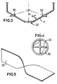
- tuyées 30 are provided, equi-spaced around the opening 22 in alignment with the lighting ports 19.
- the tuyées all lie at substantially the same angle to the vertical axis 31 of the combustion chamber 10 and also all lie at substantially the same angle to a horizontal radius of the chamber intersecting the respective tuyère.
- air entering the combustion chamber will tend to swirl around the chamber in a counter-clockwise direction and at the same time to rise upwardly within the chamber.
- Each tuyère 30 is fitted with an insert 33 so as to impart a spin on the jet of air issuing from the tuyère into the combustion chamber 10.
- the insert is in the form of a plate having a width substantially equal to the diameter of the tuyère, as shown in figure 4, and is twisted through 90° along its length. In this way, the air passing through the tuyère will be caused to swirl about the axis of the tuyère.
- the upper region 35 of the gasifier When fully operational, the upper region 35 of the gasifier will be at around 500° C and will serve as a distillation zone for high molecular weight hydrocarbons. Below that, there is a carbonisation zone 36 operating at around 600° C, where the solid fuel is converted to charcoal, by burning off other matter. On and immediately above the lower wall 11, there is established an oxidation zone 37, operating at around 1200° C, where the carbon is burned in air to form CO 2 . The hot carbon then falls through opening 22 into tube 23 and on to grate 40, there being a deficiency of oxygen in the tube 23 to continue the combustion of the carbon and so a reduction process takes place, reducing the CO 2 to CO. The final producer gas mixture leaves the lower chamber 24 through pipe 25.
- the motor 44 is operated intermittently slowly to drive the grate assembly 40.
- the eccentricity of this assembly grinds any large pieces which then fall through the lower chamber 24 and are ploughed into the discharge chute 43.
- the motor may be operated continuously, depending upon the ash content of the fuel source.
- a typical producer gas composition obtained from using wood as a fuel source may be as follows: GAS % by weight Nitrogen 45-54 carbon monoxide 18-25 hydrogen 13-15 water vapour 10-15 carbon dioxide 5-10 methane 3-5
Landscapes
- Chemical & Material Sciences (AREA)
- Engineering & Computer Science (AREA)
- Combustion & Propulsion (AREA)
- Oil, Petroleum & Natural Gas (AREA)
- Organic Chemistry (AREA)
- Mechanical Engineering (AREA)
- Gasification And Melting Of Waste (AREA)
- Acyclic And Carbocyclic Compounds In Medicinal Compositions (AREA)
- Vertical, Hearth, Or Arc Furnaces (AREA)
- Organic Low-Molecular-Weight Compounds And Preparation Thereof (AREA)
- Blast Furnaces (AREA)
- Superconductors And Manufacturing Methods Therefor (AREA)
- Processing Of Solid Wastes (AREA)
- Saccharide Compounds (AREA)
- Separation Using Semi-Permeable Membranes (AREA)
- Gas Burners (AREA)
Claims (13)
- Vergaser für die Produktion von Generatorgas aus brennbarem Material, mit einer Kammer, in die das Material eingeleitet wird, und mit einer Vielzahl von Blasdüsen (30), die an oder benachbart zu dem unteren Ende von der Kammer (11) für die Einleitung von Luft in die Brennkammer (10) angeordnet sind, wobei jede dieser Blasdüsen eine Achse definiert, entlang derer Luft in die Kammer geblasen wird, dadurch gekennzeichnet, daß zumindest einige der Blasdüsen konfiguriert sind, um eine Rotationsbewegung um die Achse herum zu erzeugen, entlang derer die Luft aus jeder der Blasdüsen in die Kammer eingeblasen wird, wodurch die Verbrennungsluft in der Form einer Düsenströmung eingeblasen wird, die um die Länge der Strömung herum wirbelt.
- Vergaser nach Anspruch 1, bei dem zumindest einige der Blasdüsen so angeordnet sind, daß ihre zugehörigen Achsen mit einem spitzen Winkel (bei Projektion auf eine horizontale Ebene, die die jeweilige Blasdüse beinhaltet) bezüglich einer Tangente an der Wand der Kammer (11) an der Position der Blasdüse verlaufen, wobei die Projektionsachse von jeder Blasdüse bezüglich der Achse (31) der Kammer in die gleiche Richtung verläuft, wodurch die ausgeblasene Luft ebenfalls dazu tendiert, um die Kammer herum zu wirbeln.
- Vergaser nach Anspruch 2, bei dem die zumindest einigen der Blasdüsen im wesentlichen mit dem gleichen spitzen Winkel bezüglich der zugehörigen Tangente an der Kammerwand an der Position der jeweiligen Blasdüsen angeordnet sind.
- Vergaser nach Anspruch 2 oder Anspruch 3, bei dem die Projektionsachse von jeder Blasdüse bezüglich der Kammer nach oben gerichtet ist, zusätzlich zu der Ausrichtung mit ihrer Achse mit einem spitzen Winkel bezüglich einer Tangente an der Wand, bei Projektion auf eine horizontale Ebene, die diese Blasdüse beinhaltet.
- Vergaser nach einem der vorhergehenden Ansprüche, bei dem alle diese Blasdüsen ähnlich konfiguriert und bezüglich der Kammer angeordnet sind.
- Vergaser nach einem der vorhergehenden Ansprüche, bei dem die Kammer zumindest in dem Bereich der Blasdüsen allgemein einen kreisförmigen Querschnitt hat, wobei die Achse der Kammer im wesentlichen vertikal verläuft.
- Vergaser nach Anspruch 6, bei dem die Vergaser-Kammer eine untere Wand (11) mit allgemein konischer Form hat, die ein Bett aus dem brennbaren Material abstützend hält, wobei die Blasdüsen in der unteren Wand montiert sind.
- Vergaser nach einem der vorhergehenden Ansprüche, bei dem die Blasdüsen im wesentlichen gleichmäßig um die Kammer herum verteilt sind.
- Vergaser nach einem der vorhergehenden Ansprüche, bei dem jede Blasdüse eine Düsenöffnung aufweist, die durch die Kammerwand vorsteht, wobei die Bohrung der Düsenöffnung so konfiguriert ist, um zu bewirken, daß die Luftströmung dadurch um die Achse der Blasdüse herum rotiert.
- Vergaser nach Anspruch 9, bei dem ein Einsatz (33) in jeder Düsenöffnung vorgesehen ist, wobei der Einsatz eine Platte aufweist, deren Breite im wesentlichen gleich dem Durchmesser der Düsenöffnung ist, und wobei die Platte entlang ihrer Länge rotiert.
- Verfahren zum Betreiben eines Vergasers für die Produktion von Generatorgas aus brennbarem Material, wobei der Vergaser eine Kammer (10), in die das Material eingeleitet (15) wird, und eine Vielzahl von Blasdüsen (30) aufweist, die an oder benachbart zu dem unteren Ende der Kammer (11) angeordnet sind, wobei bei diesem Verfahren Luft in die Brennkammer durch die Blasdüsen geblasen wird, dadurch gekennzeichnet, daß jede Blasdüse konfiguriert ist, um eine Rotationsbewegung um die Achse des Einleitens der Luft zu erzeugen, so daß die Verbrennungsluft in der Form einer Düsenströmung eingeblasen wird, die um die Länge der eingeleiteten Strömung herum wirbelt.
- Verfahren nach Anspruch 11, bei dem die Blasdüsen so angeordnet sind, daß ihre zugehörigen Achsen mit im wesentlichen dem gleichen spitzen Winkel (bei Projektion auf eine horizontale Ebene, die die jeweilige Blasdüse beinhaltet) und in der gleichen Richtung bezüglich einer Tangente an einer Wand der Kammer (11) an der Position dieser Blasdüse verlaufen, wodurch Luft, die durch die Blasdüsen in die Kammer geblasen wird, dazu neigt, um die Kammer herum zu wirbeln.
- Verfahren nach Anspruch 11 oder Anspruch 12, bei dem die Luft durch die Blasdüsen eingesogen wird, indem der Druck an dem Generatorgas-Auslaß (25) des Vergasers reduziert wird.
Applications Claiming Priority (3)
| Application Number | Priority Date | Filing Date | Title |
|---|---|---|---|
| GB9811415 | 1998-05-28 | ||
| GBGB9811415.0A GB9811415D0 (en) | 1998-05-28 | 1998-05-28 | Gasifiers |
| PCT/GB1999/001671 WO1999061561A1 (en) | 1998-05-28 | 1999-05-27 | Gasifiers with non radial tuyeres |
Publications (2)
| Publication Number | Publication Date |
|---|---|
| EP1082401A1 EP1082401A1 (de) | 2001-03-14 |
| EP1082401B1 true EP1082401B1 (de) | 2002-04-17 |
Family
ID=10832807
Family Applications (1)
| Application Number | Title | Priority Date | Filing Date |
|---|---|---|---|
| EP99923769A Expired - Lifetime EP1082401B1 (de) | 1998-05-28 | 1999-05-27 | Vergaser mit nicht radialen düsen |
Country Status (18)
| Country | Link |
|---|---|
| US (1) | US6913632B1 (de) |
| EP (1) | EP1082401B1 (de) |
| JP (1) | JP2002516381A (de) |
| AT (1) | ATE216421T1 (de) |
| AU (1) | AU753059B2 (de) |
| CA (1) | CA2333599A1 (de) |
| DE (1) | DE69901304T2 (de) |
| DK (1) | DK1082401T3 (de) |
| ES (1) | ES2175982T3 (de) |
| GB (1) | GB9811415D0 (de) |
| HU (1) | HUP0102035A3 (de) |
| IL (1) | IL139902A0 (de) |
| NO (1) | NO20005983L (de) |
| NZ (1) | NZ508479A (de) |
| PL (1) | PL344530A1 (de) |
| TR (1) | TR200003495T2 (de) |
| WO (1) | WO1999061561A1 (de) |
| ZA (1) | ZA200006925B (de) |
Cited By (1)
| Publication number | Priority date | Publication date | Assignee | Title |
|---|---|---|---|---|
| CN105255518B (zh) * | 2015-10-30 | 2021-06-04 | 上海市政工程设计研究总院(集团)有限公司 | 一种污泥裂解气化方法 |
Families Citing this family (15)
| Publication number | Priority date | Publication date | Assignee | Title |
|---|---|---|---|---|
| GB0325668D0 (en) * | 2003-11-04 | 2003-12-10 | Dogru Murat | Intensified and minaturized gasifier with multiple air injection and catalytic bed |
| JP2006083293A (ja) * | 2004-09-16 | 2006-03-30 | Fuji Electric Systems Co Ltd | バイオマス燃料のガス化装置 |
| JP2008081637A (ja) * | 2006-09-28 | 2008-04-10 | Tsukishima Kikai Co Ltd | 木質バイオマスのガス化方法及び装置 |
| JP2008081638A (ja) * | 2006-09-28 | 2008-04-10 | Tsukishima Kikai Co Ltd | 木質バイオマスのガス化方法 |
| GB0703996D0 (en) | 2007-03-01 | 2007-04-11 | Oxitec Ltd | Nucleic acid detection |
| US20090007488A1 (en) * | 2007-07-02 | 2009-01-08 | Schmidt Darren D | Charcoal/ash removal system for a downdraft gasifier and associated methods |
| US9359567B2 (en) | 2007-07-10 | 2016-06-07 | Stratean, Inc. | Gasification method using feedstock comprising gaseous fuel |
| US8105401B2 (en) * | 2007-07-10 | 2012-01-31 | Refill Energy, Inc. | Parallel path, downdraft gasifier apparatus and method |
| ITUD20110095A1 (it) | 2011-06-20 | 2012-12-21 | Toffola Daniele Della | Apparecchiatura e procedimento per la decomposizione termochimica a ciclo continuo di una biomassa |
| SG11201505847QA (en) * | 2013-01-28 | 2015-08-28 | Phg Energy Llc | Method and device for gasifying feedstock |
| US20150075071A1 (en) * | 2013-09-13 | 2015-03-19 | Joseph T. Williams | Biofuel Gasification Reactor |
| JP6632123B2 (ja) * | 2015-10-30 | 2020-01-15 | 藤原 照家 | 廃棄物ガス化装置 |
| DE102016007013B4 (de) * | 2016-06-09 | 2023-08-31 | LES Leyendecker Energy Solutions GmbH | Festbett-Brennverfahren und Anlage hierzu |
| WO2019163765A1 (ja) * | 2018-02-20 | 2019-08-29 | 明和工業株式会社 | 固体燃料のガス化装置、発電装置及びガス化方法 |
| WO2023102579A1 (en) | 2021-12-01 | 2023-06-08 | Cochrane William Thomas | Gasifier |
Family Cites Families (5)
| Publication number | Priority date | Publication date | Assignee | Title |
|---|---|---|---|---|
| CH237348A (de) * | 1943-08-07 | 1945-04-30 | Porsche Kg | Gaserzeuger. |
| US4507174A (en) * | 1983-05-10 | 1985-03-26 | Kutrieb Wolfgang A | Tire pyrolizing |
| US4583992A (en) * | 1984-12-04 | 1986-04-22 | Buck Rogers Mfg. Co., Inc. | Biomass gasifier and charcoal producer |
| NL8900939A (nl) * | 1989-04-14 | 1990-11-01 | Eduard Thomas Jacobus Van Der | Gasgenerator. |
| US5823122A (en) * | 1994-09-30 | 1998-10-20 | Alternative Energy Development, Inc. | System and process for production of fuel gas from solid biomass fuel and for combustion of such fuel gas |
-
1998
- 1998-05-28 GB GBGB9811415.0A patent/GB9811415D0/en not_active Ceased
-
1999
- 1999-05-27 CA CA002333599A patent/CA2333599A1/en not_active Abandoned
- 1999-05-27 ES ES99923769T patent/ES2175982T3/es not_active Expired - Lifetime
- 1999-05-27 AU AU40526/99A patent/AU753059B2/en not_active Ceased
- 1999-05-27 HU HU0102035A patent/HUP0102035A3/hu unknown
- 1999-05-27 NZ NZ508479A patent/NZ508479A/en unknown
- 1999-05-27 DE DE69901304T patent/DE69901304T2/de not_active Expired - Fee Related
- 1999-05-27 JP JP2000550950A patent/JP2002516381A/ja active Pending
- 1999-05-27 DK DK99923769T patent/DK1082401T3/da active
- 1999-05-27 TR TR2000/03495T patent/TR200003495T2/xx unknown
- 1999-05-27 IL IL13990299A patent/IL139902A0/xx unknown
- 1999-05-27 US US09/701,217 patent/US6913632B1/en not_active Expired - Fee Related
- 1999-05-27 EP EP99923769A patent/EP1082401B1/de not_active Expired - Lifetime
- 1999-05-27 PL PL99344530A patent/PL344530A1/xx unknown
- 1999-05-27 WO PCT/GB1999/001671 patent/WO1999061561A1/en not_active Ceased
- 1999-05-27 AT AT99923769T patent/ATE216421T1/de not_active IP Right Cessation
-
2000
- 2000-11-24 ZA ZA200006925A patent/ZA200006925B/en unknown
- 2000-11-27 NO NO20005983A patent/NO20005983L/no not_active Application Discontinuation
Cited By (1)
| Publication number | Priority date | Publication date | Assignee | Title |
|---|---|---|---|---|
| CN105255518B (zh) * | 2015-10-30 | 2021-06-04 | 上海市政工程设计研究总院(集团)有限公司 | 一种污泥裂解气化方法 |
Also Published As
| Publication number | Publication date |
|---|---|
| US6913632B1 (en) | 2005-07-05 |
| CA2333599A1 (en) | 1999-12-02 |
| EP1082401A1 (de) | 2001-03-14 |
| DE69901304T2 (de) | 2002-12-05 |
| NO20005983D0 (no) | 2000-11-27 |
| WO1999061561A1 (en) | 1999-12-02 |
| NO20005983L (no) | 2001-01-26 |
| ES2175982T3 (es) | 2002-11-16 |
| PL344530A1 (en) | 2001-11-05 |
| AU753059B2 (en) | 2002-10-03 |
| ZA200006925B (en) | 2001-11-19 |
| AU4052699A (en) | 1999-12-13 |
| HUP0102035A2 (hu) | 2001-09-28 |
| NZ508479A (en) | 2002-05-31 |
| TR200003495T2 (tr) | 2001-03-21 |
| JP2002516381A (ja) | 2002-06-04 |
| DE69901304D1 (de) | 2002-05-23 |
| HUP0102035A3 (en) | 2001-10-29 |
| GB9811415D0 (en) | 1998-07-22 |
| DK1082401T3 (da) | 2002-08-19 |
| IL139902A0 (en) | 2002-02-10 |
| ATE216421T1 (de) | 2002-05-15 |
Similar Documents
| Publication | Publication Date | Title |
|---|---|---|
| US6913632B1 (en) | Gasifiers with non radial tuyeres | |
| CN102803445B (zh) | 具有经改进的稳定性的下吸式气化炉 | |
| US5026403A (en) | Three stage process for producing producer gas from combustible waste products | |
| US6615748B2 (en) | Gasifier | |
| JPH0631341B2 (ja) | 発生炉ガス及び活性炭を製造するための方法と装置 | |
| US5573559A (en) | Method for municipal waste gasification | |
| KR101721823B1 (ko) | 가연성 폐기물 및 바이오매스 자원을 이용하는 상향식 가스화 반응기 | |
| US20110081290A1 (en) | Apparatus and process for the production of hydrogen gas | |
| KR102181822B1 (ko) | 바이오매스를 포함하는 가연성 재생 연료를 이용한 열분해가스화 시스템 | |
| CN213803653U (zh) | 下吸式生物质气化炉 | |
| KR200490378Y1 (ko) | 바이오매스 가스화장치 및 이를 갖는 바이오매스 처리설비 | |
| EP4232525B1 (de) | Verfahren zur vergasung von organischem material und anlage zur durchführung des verfahrens | |
| US9926500B2 (en) | Gasifier for solid carbon fuel with active transfer means | |
| US20060180459A1 (en) | Gasifier | |
| EP0433547B1 (de) | Vorrichtung zum Vergasen fester Brennstoffe | |
| CN105112103B (zh) | 基于真空热分解的小粒径褐煤气化装置及其气化方法 | |
| CN116875346B (zh) | 一种生物质气化炉 | |
| RU2011680C1 (ru) | Генератор газа со стационарным слоем | |
| CN115287098B (zh) | 一种等离子体气化固体废物处理装置 | |
| CA1311923C (en) | Gasification process and apparatus | |
| CA2432202C (en) | Gasifier of organic waste | |
| CA1138205A (en) | Bio-mass gasification reactor | |
| RU61390U1 (ru) | Установка для переработки горючих твердых отходов | |
| CZ279850B6 (cs) | Zplyňovací generátor, zejména kusového dřevního odpadu a pilin | |
| IT202100002540A1 (it) | Reattore di gassificazione a letto fisso equicorrente |
Legal Events
| Date | Code | Title | Description |
|---|---|---|---|
| PUAI | Public reference made under article 153(3) epc to a published international application that has entered the european phase |
Free format text: ORIGINAL CODE: 0009012 |
|
| 17P | Request for examination filed |
Effective date: 20001218 |
|
| AK | Designated contracting states |
Kind code of ref document: A1 Designated state(s): AT BE CH CY DE DK ES FI FR GB GR IE IT LI LU MC NL PT SE |
|
| GRAG | Despatch of communication of intention to grant |
Free format text: ORIGINAL CODE: EPIDOS AGRA |
|
| 17Q | First examination report despatched |
Effective date: 20010405 |
|
| GRAG | Despatch of communication of intention to grant |
Free format text: ORIGINAL CODE: EPIDOS AGRA |
|
| GRAH | Despatch of communication of intention to grant a patent |
Free format text: ORIGINAL CODE: EPIDOS IGRA |
|
| REG | Reference to a national code |
Ref country code: GB Ref legal event code: IF02 |
|
| GRAH | Despatch of communication of intention to grant a patent |
Free format text: ORIGINAL CODE: EPIDOS IGRA |
|
| GRAA | (expected) grant |
Free format text: ORIGINAL CODE: 0009210 |
|
| AK | Designated contracting states |
Kind code of ref document: B1 Designated state(s): AT BE CH CY DE DK ES FI FR GB GR IE IT LI LU MC NL PT SE |
|
| PG25 | Lapsed in a contracting state [announced via postgrant information from national office to epo] |
Ref country code: GR Free format text: LAPSE BECAUSE OF FAILURE TO SUBMIT A TRANSLATION OF THE DESCRIPTION OR TO PAY THE FEE WITHIN THE PRESCRIBED TIME-LIMIT Effective date: 20020417 Ref country code: FI Free format text: LAPSE BECAUSE OF FAILURE TO SUBMIT A TRANSLATION OF THE DESCRIPTION OR TO PAY THE FEE WITHIN THE PRESCRIBED TIME-LIMIT Effective date: 20020417 |
|
| REF | Corresponds to: |
Ref document number: 216421 Country of ref document: AT Date of ref document: 20020515 Kind code of ref document: T |
|
| REG | Reference to a national code |
Ref country code: CH Ref legal event code: EP |
|
| REG | Reference to a national code |
Ref country code: IE Ref legal event code: FG4D |
|
| REF | Corresponds to: |
Ref document number: 69901304 Country of ref document: DE Date of ref document: 20020523 |
|
| PG25 | Lapsed in a contracting state [announced via postgrant information from national office to epo] |
Ref country code: MC Free format text: LAPSE BECAUSE OF NON-PAYMENT OF DUE FEES Effective date: 20020527 Ref country code: LU Free format text: LAPSE BECAUSE OF NON-PAYMENT OF DUE FEES Effective date: 20020527 |
|
| PG25 | Lapsed in a contracting state [announced via postgrant information from national office to epo] |
Ref country code: CY Free format text: LAPSE BECAUSE OF FAILURE TO SUBMIT A TRANSLATION OF THE DESCRIPTION OR TO PAY THE FEE WITHIN THE PRESCRIBED TIME-LIMIT Effective date: 20020531 |
|
| PG25 | Lapsed in a contracting state [announced via postgrant information from national office to epo] |
Ref country code: PT Free format text: LAPSE BECAUSE OF FAILURE TO SUBMIT A TRANSLATION OF THE DESCRIPTION OR TO PAY THE FEE WITHIN THE PRESCRIBED TIME-LIMIT Effective date: 20020717 |
|
| REG | Reference to a national code |
Ref country code: DK Ref legal event code: T3 |
|
| REG | Reference to a national code |
Ref country code: CH Ref legal event code: NV Representative=s name: ISLER & PEDRAZZINI AG |
|
| ET | Fr: translation filed | ||
| REG | Reference to a national code |
Ref country code: ES Ref legal event code: FG2A Ref document number: 2175982 Country of ref document: ES Kind code of ref document: T3 |
|
| PGFP | Annual fee paid to national office [announced via postgrant information from national office to epo] |
Ref country code: ES Payment date: 20021125 Year of fee payment: 4 |
|
| PLBE | No opposition filed within time limit |
Free format text: ORIGINAL CODE: 0009261 |
|
| STAA | Information on the status of an ep patent application or granted ep patent |
Free format text: STATUS: NO OPPOSITION FILED WITHIN TIME LIMIT |
|
| REG | Reference to a national code |
Ref country code: IE Ref legal event code: MM4A |
|
| 26N | No opposition filed |
Effective date: 20030120 |
|
| PG25 | Lapsed in a contracting state [announced via postgrant information from national office to epo] |
Ref country code: GB Free format text: LAPSE BECAUSE OF NON-PAYMENT OF DUE FEES Effective date: 20030527 |
|
| PG25 | Lapsed in a contracting state [announced via postgrant information from national office to epo] |
Ref country code: ES Free format text: LAPSE BECAUSE OF NON-PAYMENT OF DUE FEES Effective date: 20030528 |
|
| REG | Reference to a national code |
Ref country code: CH Ref legal event code: PL |
|
| GBPC | Gb: european patent ceased through non-payment of renewal fee |
Effective date: 20030527 |
|
| REG | Reference to a national code |
Ref country code: GB Ref legal event code: 728V |
|
| PG25 | Lapsed in a contracting state [announced via postgrant information from national office to epo] |
Ref country code: FR Free format text: LAPSE BECAUSE OF NON-PAYMENT OF DUE FEES Effective date: 20040130 |
|
| REG | Reference to a national code |
Ref country code: CH Ref legal event code: AEN Free format text: REMISE EN VIGUEUR APRES RADIATION ERRONEE |
|
| REG | Reference to a national code |
Ref country code: FR Ref legal event code: ST |
|
| REG | Reference to a national code |
Ref country code: FR Ref legal event code: RN |
|
| REG | Reference to a national code |
Ref country code: FR Ref legal event code: D3 |
|
| REG | Reference to a national code |
Ref country code: ES Ref legal event code: FD2A Effective date: 20030528 |
|
| PGFP | Annual fee paid to national office [announced via postgrant information from national office to epo] |
Ref country code: FR Payment date: 20041129 Year of fee payment: 6 |
|
| PGFP | Annual fee paid to national office [announced via postgrant information from national office to epo] |
Ref country code: SE Payment date: 20041130 Year of fee payment: 6 Ref country code: NL Payment date: 20041130 Year of fee payment: 6 Ref country code: IE Payment date: 20041130 Year of fee payment: 6 Ref country code: DK Payment date: 20041130 Year of fee payment: 6 Ref country code: DE Payment date: 20041130 Year of fee payment: 6 Ref country code: CH Payment date: 20041130 Year of fee payment: 6 Ref country code: AT Payment date: 20041130 Year of fee payment: 6 |
|
| PGFP | Annual fee paid to national office [announced via postgrant information from national office to epo] |
Ref country code: BE Payment date: 20041214 Year of fee payment: 6 |
|
| PG25 | Lapsed in a contracting state [announced via postgrant information from national office to epo] |
Ref country code: IT Free format text: LAPSE BECAUSE OF NON-PAYMENT OF DUE FEES Effective date: 20050527 Ref country code: AT Free format text: LAPSE BECAUSE OF NON-PAYMENT OF DUE FEES Effective date: 20050527 |
|
| PG25 | Lapsed in a contracting state [announced via postgrant information from national office to epo] |
Ref country code: SE Free format text: LAPSE BECAUSE OF NON-PAYMENT OF DUE FEES Effective date: 20050528 |
|
| PG25 | Lapsed in a contracting state [announced via postgrant information from national office to epo] |
Ref country code: LI Free format text: LAPSE BECAUSE OF NON-PAYMENT OF DUE FEES Effective date: 20050531 Ref country code: DK Free format text: LAPSE BECAUSE OF NON-PAYMENT OF DUE FEES Effective date: 20050531 Ref country code: CH Free format text: LAPSE BECAUSE OF NON-PAYMENT OF DUE FEES Effective date: 20050531 Ref country code: BE Free format text: LAPSE BECAUSE OF NON-PAYMENT OF DUE FEES Effective date: 20050531 |
|
| REG | Reference to a national code |
Ref country code: GB Ref legal event code: 728Y |
|
| BERE | Be: lapsed |
Owner name: *DEDAR LTD Effective date: 20050531 |
|
| PG25 | Lapsed in a contracting state [announced via postgrant information from national office to epo] |
Ref country code: NL Free format text: LAPSE BECAUSE OF NON-PAYMENT OF DUE FEES Effective date: 20051201 Ref country code: DE Free format text: LAPSE BECAUSE OF NON-PAYMENT OF DUE FEES Effective date: 20051201 |
|
| REG | Reference to a national code |
Ref country code: CH Ref legal event code: PL |
|
| EUG | Se: european patent has lapsed | ||
| NLV4 | Nl: lapsed or anulled due to non-payment of the annual fee |
Effective date: 20051201 |
|
| REG | Reference to a national code |
Ref country code: IE Ref legal event code: MM4A |
|
| REG | Reference to a national code |
Ref country code: DK Ref legal event code: EBP |
|
| REG | Reference to a national code |
Ref country code: FR Ref legal event code: ST Effective date: 20060131 |
|
| BERE | Be: lapsed |
Owner name: *DEDAR LTD Effective date: 20050531 |
|
| PGFP | Annual fee paid to national office [announced via postgrant information from national office to epo] |
Ref country code: GB Payment date: 20120522 Year of fee payment: 14 |
|
| GBPC | Gb: european patent ceased through non-payment of renewal fee |
Effective date: 20130527 |
|
| PG25 | Lapsed in a contracting state [announced via postgrant information from national office to epo] |
Ref country code: GB Free format text: LAPSE BECAUSE OF NON-PAYMENT OF DUE FEES Effective date: 20130527 |