EP1083019A2 - Maschine und Verfahren zum thermischen Schneiden, insbesondere zum Laserschneiden, von Werkstücken - Google Patents
Maschine und Verfahren zum thermischen Schneiden, insbesondere zum Laserschneiden, von Werkstücken Download PDFInfo
- Publication number
- EP1083019A2 EP1083019A2 EP00118931A EP00118931A EP1083019A2 EP 1083019 A2 EP1083019 A2 EP 1083019A2 EP 00118931 A EP00118931 A EP 00118931A EP 00118931 A EP00118931 A EP 00118931A EP 1083019 A2 EP1083019 A2 EP 1083019A2
- Authority
- EP
- European Patent Office
- Prior art keywords
- workpiece support
- workpiece
- stop
- support
- adhering
- Prior art date
- Legal status (The legal status is an assumption and is not a legal conclusion. Google has not performed a legal analysis and makes no representation as to the accuracy of the status listed.)
- Granted
Links
Images



Classifications
-
- B—PERFORMING OPERATIONS; TRANSPORTING
- B23—MACHINE TOOLS; METAL-WORKING NOT OTHERWISE PROVIDED FOR
- B23K—SOLDERING OR UNSOLDERING; WELDING; CLADDING OR PLATING BY SOLDERING OR WELDING; CUTTING BY APPLYING HEAT LOCALLY, e.g. FLAME CUTTING; WORKING BY LASER BEAM
- B23K26/00—Working by laser beam, e.g. welding, cutting or boring
- B23K26/16—Removal of by-products, e.g. particles or vapours produced during treatment of a workpiece
-
- B—PERFORMING OPERATIONS; TRANSPORTING
- B23—MACHINE TOOLS; METAL-WORKING NOT OTHERWISE PROVIDED FOR
- B23K—SOLDERING OR UNSOLDERING; WELDING; CLADDING OR PLATING BY SOLDERING OR WELDING; CUTTING BY APPLYING HEAT LOCALLY, e.g. FLAME CUTTING; WORKING BY LASER BEAM
- B23K26/00—Working by laser beam, e.g. welding, cutting or boring
- B23K26/08—Devices involving relative movement between laser beam and workpiece
- B23K26/10—Devices involving relative movement between laser beam and workpiece using a fixed support, i.e. involving moving the laser beam
Definitions
- the invention relates to a machine for thermal cutting of workpieces, especially a laser cutting machine, with at least one workpiece support for the workpiece to be machined and at least one cutting device.
- the invention further relates to a machine of the type described kind of feasible method for thermal cutting, in particular for laser cutting of workpieces, after processing of a workpiece free material to be cut and a workpiece support be moved relative to each other.
- the object according to the invention is device-related by means of a Machine of the type described in the introduction, which at least one machine device for generating a relative movement the workpiece support and from after machining of a workpiece that is clinging to the workpiece support comprises, said device at least one stop for clippings adhering to the workpiece support and the stop and the workpiece support by loosening the latter clinging material is movable relative to each other are.
- the measure described in claim 3 is particularly for Machines according to the invention with a stationary workpiece support from Advantage.
- the stop for sticking to the workpiece support Cuttings can then move with respect to the anyway Workpiece support moving machine parts are coupled.
- Claims 10 to 13 describe embodiments of the invention Machine, in the case of which a movement of the Workpiece support for the removal of adhering to it Cutting material is used. Particularly space-saving machine types result from claims 12 and 13.
- An automated operation of the machine according to the invention serves the feature of claim 14, according to which the device for Generation of a relative movement of the workpiece support and on this sticky cutting material by means of the computer control of Machine is controllable.
- Claim 16 is the solution to the above-mentioned process-related Remove task.
- the invention as part of a procedure of the type described at the beginning free material to be cut and the workpiece support after processing of a workpiece while striking free material to be cut of the workpiece support clinging material perpendicular to the direction the workpiece support on the workpiece support relative to each other emotional.
- This relative movement allows the Work piece support clinging material by means of freely movable Reliably cut material to be cut from the workpiece support.
- there can be the amount of the described relative movement in the transverse direction the workpiece support on the workpiece support is very low be and are in the millimeter range.
- Claim 17 describes a preferred variant of the invention Procedure, which is characterized in that the as Free cut material used at most over a short stop Distance slides on the workpiece support and accordingly is exposed to a minimal amount of rubbing stress.
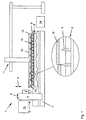
- a laser cutting machine 1 comprises a cutting device in the form of a laser cutting head 2, which in known Is held on a machine portal 3, of which in Figure 1 only one of the two vertical supports, namely a vertical support 4 can be seen.
- the horizontal support of the machine portal 3 is the laser cutting head 2 driven perpendicular to the drawing plane of Figure 1 movable.
- the laser cutting head is 2 in Direction of a double arrow 5 can be raised and lowered.
- the machine portal 3 can be shared with the laser cutting head 2 move in the direction of a double arrow 6 and is at his Traversing movement performed on a machine base frame 7.
- a stationary workpiece support is overlapped by the machine portal 3 8 with rib-like projections 9, which are shown in the Example case for storing a workpiece in shape serve a sheet.
- a workpiece transport device is also part of the laser cutting machine 1 11 common design.
- One as a lifting frame 12 trained holder of the workpiece transport device 11 movable in the three coordinate directions of the room and carries a plurality of pneumatic suction cups on its underside 13.
- a computer control 14 serves to control all machine functions the laser cutting machine 1 including the Workpiece transport device 11 and a laser generator 15, by means of which the laser cutting beam for workpiece processing is produced.
- the conditions on the laser cutting machine are shown in FIG 1 after finishing the processing of the sheet.
- the unprocessed sheet metal using the workpiece transport device 11 have been placed on the workpiece support 8.
- the sheet to be processed was with a corresponding one Separation cut of the laser cutting head 2 perpendicular to the The drawing plane has been split in half, then from both Sheet metal halves using the correspondingly moved laser cutting head Cut out 2 individual contours as cutting waste were.
- the cutting waste was - like that enlarged Representation detail of Figure 1 shows - undesirably with individual of the rib-like projections 9 of the workpiece support 8 have been welded.
- the lifting frame 12 of the workpiece transport device 11 had the cut sheet metal parts 10 after machining in the direction of the workpiece support on the Workpiece support 8 from the latter into the position according to FIG. 1 raised.
- the amount of this lifting movement was less than that Thickness of the cutting waste adhering to the workpiece support 8, i.e. smaller than the dimension of the mentioned cutting waste in Direction of stroke and the conditions according to FIG. 1 resulted.
- the workpiece support 8 preferably has this Purpose of a lattice structure through the openings of which Cutting waste can fall through before the operator the laser cutting machine 1 is finally removed.
- perpendicular to each other partial movements of the cut sheet metal parts 10 can be used to release the cutting waste from the workpiece support 8 also a steady, oblique movement of the cut Sheet metal parts 10 relative to the workpiece support 8 and the cutting waste adhering to it.
- the device for generating the required to release the cutting waste from the workpiece support 8 Relative movement of cutting waste and workpiece support 8 formed by the workpiece transport device 11 with the held on it and as stops for the one to be solved Cut sheet metal parts serving for cutting waste 10.
- FIG. 1 Possibility to remove adhering to a workpiece support
- Figure 2 shows cutting material in the form of cutting waste for a Laser cutting machine 21.
- This has an exclusively as such device 36 used to generate a relative movement the workpiece support 8 and adhering to it Cutting waste.
- the device 36 consists essentially from a pneumatic telescopic cylinder 37 and an attached to it Stop 30 for adhering to the workpiece support 8 Cutting waste.
- the telescopic cylinder 37 is extended as soon as the processing of the relevant sheet ends and the cut ones Sheet metal parts 10 by means of the workpiece transport device 11 are lifted off the workpiece support 8.
- the telescopic cylinder 37 is retracted into its starting position.
- the computer control is used to control the telescopic cylinder 37 14 of the laser cutting machine 21.
- FIG. 3 this is used in the case of a laser cutting machine 41
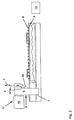
- Machine portal 3 movable in the direction of the double arrow 6 with an attached stop 50 as a device for Generation of the relative movement of workpiece support 8 and thereon adhesive cutting waste.
- the stop 50 is in the direction of the double arrow 5 can be raised and lowered.
- the stop 50 is raised and located himself in its resting position.
- the Cut sheet metal parts not shown, for simplicity by means of a workpiece transport device, also not shown lifted off the workpiece support 8 before the Stop 50 from its rest position to that shown in FIG Working position moves.
- Machine portal 3 Starting position in the illustration to the right and breaks with the stop 50 with the rib-like projections 9 the workpiece support 8 welded cutting waste. Also the described functions of the stop 50 and the machine portal 3 by means of the computer control 14 of the laser cutting machine 41 controlled.
- the machine portal 3 is part of the device for generation a relative movement of the workpiece support 8 and sticking to this cutting waste.
- the cut sheet metal parts 10 By means of a attached to the machine portal 3 holder in the form of a Gripper 78 becomes one of the cut sheet metal parts 10 Completed his cutting and starting from his in Figure 4 shown starting position in the illustration shifted to the right. He also moves the other tailored one Sheet metal part 10 accordingly.
- the one on the rib-like Projections 9 of the workpiece support 8 welded cutting waste it breaks loose.
- the amount by means of the machine portal 3 caused relative movement of the cut Sheet metal parts 10 with respect to the workpiece support 8 or the workpiece thereon sticky cutting waste is in the millimeter range.
- the described relative movement of the machine portal 3 with the held on it cut sheet metal part 10 and the workpiece support 8 and the coupling of the gripper 78 to the Sheet metal part 10 are by means of the computer control 14 of the laser cutting machine 61 controlled.
- the machine portal 3 with the He grips 78 can also be used as a workpiece transport device for loading the workpiece support 8 with metal sheets to be machined and / or for removing the cut sheet metal parts 10 use of the workpiece support 8 and can then additionally or alternatively to a workpiece transport device 11 of the above described type can be used.
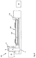
- Laser cutting machines 81 shown in FIGS. 5 and 6, 101 differ from the laser cutting machines described above 1, 21, 41, 61 in that workpiece supports 88, 108 are movable relative to stationary stops 90, 110, in order to release the cutting waste Relative movement of cutting waste and the respective one To produce workpiece support 88, 108.
- the workpiece support 88 by means of a revolving drive belt 99 in its entirety in a horizontal Direction, i.e. across the direction of the workpiece support moved to the workpiece support 88.
- a revolving drive belt 99 in its entirety in a horizontal Direction, i.e. across the direction of the workpiece support moved to the workpiece support 88.
- On rib-like Projections 89 of the workpiece support 88 sticking cutting waste runs on the stop 90 and is thereby by the Workpiece support 88 broken loose.
- the stop 110 of the laser cutting machine also acts like a scraper 101 according to FIG. 6. Deviating from the machine type 5 is the workpiece support 108 of the laser cutting machine 101 but endless on one strand 120 circumferential rib chain.
- the workpiece supports 88, 108 form with the associated stop 90, 110 the respective device for generating the relative movement the workpiece support 88, 108 and on this clinging waste.
- the laser cutting machines can also 41, 61, 81, 101 with a workpiece transport device 11 be equipped according to Figures 1 and 2.
- Corresponding machine components are in the different Representations assigned identical reference numerals.
Landscapes
- Physics & Mathematics (AREA)
- Optics & Photonics (AREA)
- Engineering & Computer Science (AREA)
- Plasma & Fusion (AREA)
- Mechanical Engineering (AREA)
- Laser Beam Processing (AREA)
- Turning (AREA)
- Dicing (AREA)
Abstract
Description
- Figur 1
- eine erste Bauart einer Laserschneidmaschine mit einem vergrößerten Darstellungsdetail,
- Figur 2
- eine zweite Bauart einer Laserschneidmaschine mit einem vergrößerten Darstellungsdetail,
- Figur 3
- eine dritte Bauart einer Laserschneidmaschine,
- Figur 4
- eine vierte Bauart einer Laserschneidmaschine,
- Figur 5
- eine fünfte Bauart einer Laserschneidmaschine und
- Figur 6
- eine sechste Bauart einer Laserschneidmaschine.
Claims (17)
- Maschine zum thermischen Schneiden von Werkstücken, insbesondere Laserschneidmaschine, mit wenigstens einer Werkstückauflage (8, 88, 108) für das zu bearbeitende Werkstück sowie zumindest einer Schneideinrichtung (2), gekennzeichnet durch wenigstens eine maschinelle Vorrichtung (10, 11; 36; 3, 50; 3, 10, 78; 88, 90; 108, 110) zur Erzeugung einer Relativbewegung der Werkstückauflage (8, 88, 108) und von nach der Bearbeitung eines Werkstücks an der Werkstückauflage (8, 88, 108) haftendem Schneidgut, mit zumindest einem Anschlag (10, 30, 50, 90, 110) für an der Werkstückauflage (8, 88, 108) haftendes Schneidgut, wobei der Anschlag (10, 30, 50, 90, 110) und die Werkstückauflage (8, 88, 108) unter Lösen von an letzterer haftendem Schneidgut relativ zueinander bewegbar sind.
- Maschine nach einem der vorhergehenden Ansprüche, dadurch gekennzeichnet, daß die Richtung der Relativbewegung der Werkstückauflage (8, 88, 108) und des Anschlages (10, 30, 50, 90, 110) für an letzterer haftendes Schneidgut quer zu der Richtung der Werkstückabstützung an der Werkstückauflage (8, 88, 108) verläuft.
- Maschine nach einem der vorhergehenden Ansprüche, dadurch gekennzeichnet, daß der Anschlag (10, 30, 50) für an der Werkstückauflage (8) haftendes Schneidgut an der Werkstückauflage (8) entlang bewegbar ist.
- Maschine nach einem der vorhergehenden Ansprüche mit zumindest einer Werkstück-Transportvorrichtung (11; 3, 78) zum Beschicken der Werkstückauflage (8) mit wenigstens einem zu bearbeitenden Werkstück und/oder zum Entfernen von Schneidgut von der Werkstückauflage (8) nach der Werkstückbearbeitung, wobei die Werkstück-Transportvorrichtung (11; 3, 78) wenigstens einen Halter (12, 78) für das zu bearbeitende Werkstück und/oder für zu entfernendes Schneidgut aufweist und die Werkstückauflage (8) und der Halter (12, 78) relativ zueinander bewegbar sind, dadurch gekennzeichnet, daß die Werkstück-Transportvorrichtung (11; 3, 78) wenigstens Teil der Vorrichtung (10, 11; 3, 10, 78) zur Erzeugung einer Relativbewegung von Werkstückauflage (8) und an dieser haftendem Schneidgut ist, wobei der Anschlag (10) für an der Werkstückauflage (8) haftendes Schneidgut an dem Halter (12, 78) der Werkstück-Transportvorrichtung (11; 3, 78) vorgesehen ist.
- Maschine nach einem der vorhergehenden Ansprüche, dadurch gekennzeichnet, daß als Anschlag (10) für an der Werkstückauflage (8) haftendes Schneidgut wenigstens ein an dem Halter (12, 78) der Werkstück-Transportvorrichtung (11; 3, 78) gehaltenes zu bearbeitendes Werkstück und/oder entsprechendes, mit dem Halter (12, 78) relativ zu der Werkstückauflage (8) bewegbares freies Schneidgut (10) vorgesehen ist.
- Maschine nach einem der vorhergehenden Ansprüche mit zumindest einer Werkstück-Transportvorrichtung (11; 3, 78) zum Entfernen von freiem Schneidgut (10) von der Werkstückauflage (8) nach der Bearbeitung eines Werkstückes, wobei die Werkstückauflage (8) und an dem Halter (12, 78) der Werkstück-Transportvorrichtung (11; 3, 78) gehaltenes freies Schneidgut (10) relativ zueinander bewegbar sind, dadurch gekennzeichnet, daß als Anschlag (10) für an der Werkstückauflage (8) haftendes Schneidgut der vorausgegangenen Werkstückbearbeitung dabei angefallenes, an dem Halter (12, 78) der Werkstück-Transportvorrichtung (11; 3, 78) gehaltenes freies Schneidgut (10) vorgesehen ist.
- Maschine nach einem der vorhergehenden Ansprüche, dadurch gekennzeichnet, daß die Werkstückauflage (8) und das als Anschlag (10) für an der Werkstückauflage (8) haftendes Schneidgut dienende Werkstück bzw. das entsprechende freie Schneidgut (10) relativ zueinander quer zu der Richtung der Werkstückabstützung an der Werkstückauflage (8) bewegbar sind.
- Maschine nach einem der vorhergehenden Ansprüche, wobei die Schneideinrichtung (2) und die Werkstückauflage (8) angetrieben relativ zueinander bewegbar sind, dadurch gekennzeichnet, daß wenigstens ein Anschlag (50, 10) für an der Werkstückauflage (8) haftendes Schneidgut mit der Schneideinrichtung (2) gekoppelt relativbewegbar ist.
- Maschine nach einem der vorhergehenden Ansprüche, wobei die Schneideinrichtung (2) an einem Maschinenportal (3) gehalten ist, welches die Werkstückauflage (8) übergreift und quer zu der Richtung der Werkstückabstützung an der Werkstückauflage (8) relativ zu letzterer angetrieben bewegbar ist, dadurch gekennzeichnet, daß wenigstens ein Anschlag (50, 10) für an der Werkstückauflage (8) haftendes Schneidgut an dem Maschinenportal (3) angebracht ist.
- Maschine nach einem der vorhergehenden Ansprüche, dadurch gekennzeichnet, daß die Werkstückauflage (88, 108) angetrieben an wenigstens einem Anschlag (90, 110) für an ihr haftendes Schneidgut entlang bewegbar ist.
- Maschine nach einem der vorhergehenden Ansprüche, dadurch gekennzeichnet, daß die Werkstückauflage (88, 108) quer zu der Richtung der Werkstückabstützung an der Werkstückauflage (88, 108) an wenigstens einem Anschlag (90, 110) für an ihr haftendes Schneidgut entlang bewegbar ist.
- Maschine nach einem der vorhergehenden Ansprüche, dadurch gekennzeichnet, daß die Werkstückauflage (108) unter wenigstens einfacher Umlenkung in Richtung der Werkstückabstützung an der Werkstückauflage (108) quer zu der genannten Richtung bewegbar ist.
- Maschine nach einem der vorhergehenden Ansprüche, dadurch gekennzeichnet, daß die Werkstückauflage (108) an einem Trum (120) wenigstens einer endlos umlaufend bewegbaren Kette und/oder eines entsprechenden Bandes oder dergleichen ausgebildet und die genannte Kette und/oder das genannte Band oder dergleichen an wenigstens einem Anschlag (110) für an der Werkstückauflage (108) haftendes Schneidgut entlang bewegbar ist.
- Maschine nach einem der vorhergehenden Ansprüche mit einer Rechnersteuerung (14) für Maschinenfunktionen, dadurch gekennzeichnet, daß die Vorrichtung (10, 11; 36; 3, 50; 3, 10, 78; 88, 90; 108, 110) zur Erzeugung einer Relativbewegung von Werkstückauflage (8, 88, 108) und an dieser haftendem Schneidgut mittels der Rechnersteuerung (14) steuerbar ist.
- Maschine nach einem der vorhergehenden Ansprüche, dadurch gekennzeichnet, daß der Anschlag (10, 30, 50, 90, 110) für an der Werkstückauflage (8, 88, 108) haftendes Schneidgut und die Werkstückauflage (8, 88, 108) nach einer schneidenden Werkstückbearbeitung mittels der Rechnersteuerung (14) routinemäßig quer zu der Richtung der Werkstückabstützung an der Werkstückauflage (8, 88, 108) gesteuert relativ zueinander bewegbar sind, gegebenenfalls unter Anschlagen des Anschlages (10, 30, 50, 90, 110) an an der Werkstückauflage (8, 88, 108) haftendem Schneidgut.
- Verfahren zum thermischen Schneiden, insbesondere zum Laserschneiden, von Werkstücken, durchgeführt mit einer Maschine nach einem der vorhergehenden Ansprüche, wobei nach der Bearbeitung eines Werkstückes freies Schneidgut (10) und eine Werkstückauflage (8) relativ zueinander bewegt werden, dadurch gekennzeichnet, daß nach der Bearbeitung eines Werkstückes freies Schneidgut (10) und die Werkstückauflage (8) unter Anschlagen von freiem Schneidgut (10) an an der Werkstückauflage (8) haftendem Schneidgut quer zu der Richtung der Werkstückabstützung an der Werkstückauflage (8) relativ zueinander bewegt werden.
- Verfahren nach Anspruch 16, dadurch gekennzeichnet, daß das freie Schneidgut (10) und die Werkstückauflage (8) vor oder mit ihrer Relativbewegung quer zu der Richtung der Werkstückabstützung an der Werkstückauflage (8) in Richtung der Werkstückabstützung an der Werkstückauflage (8) um einen Betrag relativ zueinander bewegt werden, der kleiner ist als die Abmessung von an der Werkstückauflage (8) haftendem Schneidgut in der letztgenannten Richtung.
Applications Claiming Priority (2)
| Application Number | Priority Date | Filing Date | Title |
|---|---|---|---|
| DE19943043 | 1999-09-09 | ||
| DE19943043A DE19943043C2 (de) | 1999-09-09 | 1999-09-09 | Maschine und Verfahren zum thermischen Schneiden, insbesondere zum Laserschneiden, von Werkstücken |
Publications (3)
| Publication Number | Publication Date |
|---|---|
| EP1083019A2 true EP1083019A2 (de) | 2001-03-14 |
| EP1083019A3 EP1083019A3 (de) | 2002-11-27 |
| EP1083019B1 EP1083019B1 (de) | 2004-11-24 |
Family
ID=7921318
Family Applications (1)
| Application Number | Title | Priority Date | Filing Date |
|---|---|---|---|
| EP00118931A Expired - Lifetime EP1083019B1 (de) | 1999-09-09 | 2000-09-01 | Maschine und Verfahren zum thermischen Schneiden, insbesondere zum Laserschneiden, von Werkstücken |
Country Status (4)
| Country | Link |
|---|---|
| US (2) | US6509545B1 (de) |
| EP (1) | EP1083019B1 (de) |
| AT (1) | ATE283141T1 (de) |
| DE (2) | DE19943043C2 (de) |
Cited By (4)
| Publication number | Priority date | Publication date | Assignee | Title |
|---|---|---|---|---|
| DE202004021725U1 (de) | 2004-06-05 | 2010-07-15 | Trumpf Werkzeugmaschinen Gmbh + Co. Kg | Laserbearbeitungsmaschine mit Strahldiagnosevorrichtung zur Bestimmung wenigstens eines Strahlkenndatums eines Laserstrahls an einer Laserbearbeitungsmaschine |
| CN104812521A (zh) * | 2012-11-13 | 2015-07-29 | 村田机械株式会社 | 热切割加工系统 |
| SE1751548A1 (en) * | 2017-12-14 | 2019-06-15 | Tomologic Ab | A method and a system for handling beam-cut parts |
| SE1751549A1 (en) * | 2017-12-14 | 2019-06-15 | Tomologic Ab | A table, method and system for handling beam-cut parts |
Families Citing this family (11)
| Publication number | Priority date | Publication date | Assignee | Title |
|---|---|---|---|---|
| DE20112006U1 (de) | 2001-07-24 | 2002-02-28 | Diem Reinhard | Vorrichtung zur Lagerung von flächigen Materialien beim Trennen mittels Trenneinrichtung |
| EP1340584B1 (de) | 2002-02-16 | 2006-07-05 | Trumpf Werkzeugmaschinen GmbH + Co. KG | Maschine zum thermischen Schneiden von Werkstücken insbesondere mittels Laser |
| EP1393847B1 (de) | 2002-08-30 | 2012-03-21 | TRUMPF Werkzeugmaschinen GmbH + Co. KG | Werkstücksauflage einer Maschine zum thermischen Schneiden von Werkstücken und Verfahren zu deren Herstellung |
| DE10250229B4 (de) | 2002-10-29 | 2004-08-05 | Hüttinger Elektronik GmbH & Co. KG | Leistungsregelung für Hochfrequenzverstärker |
| EP2029312B1 (de) * | 2006-05-24 | 2013-01-23 | TRUMPF Werkzeugmaschinen GmbH + Co. KG | Bearbeitungsanlage mit einer werkstückauflage zur aufnahme eines insbesondere tafelförmigen werkstücks mit auf auflageelementen anbringbaren tragelementen |
| DE102006027521B4 (de) * | 2006-06-10 | 2016-01-07 | Edwin Kohl | Anlage zur personenbezogenen Bestückung von Medikamentenspendern |
| US20090044880A1 (en) * | 2007-06-16 | 2009-02-19 | Jody Jones | Log cutting |
| US20100126320A1 (en) * | 2008-11-21 | 2010-05-27 | Trumpf, Inc. | Vacuum based part separation |
| JP6046065B2 (ja) * | 2014-02-07 | 2016-12-14 | 株式会社エイチアンドエフ | 分離回収装置及びそれを用いた部品の取出方法 |
| CN106773159B (zh) * | 2016-12-12 | 2018-04-10 | 惠科股份有限公司 | 一种残材去除装置 |
| CN107283102A (zh) * | 2017-08-08 | 2017-10-24 | 柳州市开宇机器人有限公司 | 一种上板机焊接器 |
Family Cites Families (10)
| Publication number | Priority date | Publication date | Assignee | Title |
|---|---|---|---|---|
| US3764775A (en) * | 1972-01-19 | 1973-10-09 | Hughes Aircraft Co | Error compensation in tool movement over intermittently advanced work support surface |
| CH637862A5 (fr) * | 1980-10-23 | 1983-08-31 | Raskin Sa | Machine a decouper un materiau en feuille. |
| DE3410913A1 (de) * | 1984-03-24 | 1985-10-03 | Trumpf GmbH & Co, 7257 Ditzingen | Werkzeugmaschine zur mechanischen und laserstrahl-bearbeitung eines werkstuecks |
| US4672172A (en) * | 1985-12-19 | 1987-06-09 | Gerber Garment Technology, Inc. | Workpiece supporting bed for laser cutter |
| JPH01289590A (ja) * | 1988-05-16 | 1989-11-21 | Shinko Kogyo Co Ltd | 多頭式のレーザ加工装置 |
| US4940880A (en) * | 1989-09-11 | 1990-07-10 | Trumpf Gmbh & Co. | Combination punch press and laser cutting machine with laser beam generator mounted thereon |
| US5338914A (en) * | 1992-03-11 | 1994-08-16 | Kabushiki Kaisha Komatsu Seisakusho | Thermal cutting machine |
| JPH06142914A (ja) * | 1992-11-13 | 1994-05-24 | Komatsu Ltd | 熱切断加工機のワーク搬送装置 |
| JPH08132242A (ja) * | 1994-07-21 | 1996-05-28 | Fuji Heavy Ind Ltd | プラズマ穴明け加工装置および冷却方法 |
| FR2787363B1 (fr) * | 1998-12-22 | 2001-01-19 | Soudure Autogene Francaise | Procede d'oxycoupage avec prechauffage par plasma de materiaux ferreux, tels les aciers de construction |
-
1999
- 1999-09-09 DE DE19943043A patent/DE19943043C2/de not_active Expired - Lifetime
-
2000
- 2000-09-01 DE DE50008729T patent/DE50008729D1/de not_active Expired - Lifetime
- 2000-09-01 AT AT00118931T patent/ATE283141T1/de not_active IP Right Cessation
- 2000-09-01 EP EP00118931A patent/EP1083019B1/de not_active Expired - Lifetime
- 2000-09-08 US US09/657,795 patent/US6509545B1/en not_active Expired - Lifetime
-
2002
- 2002-12-03 US US10/308,305 patent/US6642479B2/en not_active Expired - Lifetime
Cited By (5)
| Publication number | Priority date | Publication date | Assignee | Title |
|---|---|---|---|---|
| DE202004021725U1 (de) | 2004-06-05 | 2010-07-15 | Trumpf Werkzeugmaschinen Gmbh + Co. Kg | Laserbearbeitungsmaschine mit Strahldiagnosevorrichtung zur Bestimmung wenigstens eines Strahlkenndatums eines Laserstrahls an einer Laserbearbeitungsmaschine |
| CN104812521A (zh) * | 2012-11-13 | 2015-07-29 | 村田机械株式会社 | 热切割加工系统 |
| CN104812521B (zh) * | 2012-11-13 | 2016-08-31 | 村田机械株式会社 | 热切割加工系统 |
| SE1751548A1 (en) * | 2017-12-14 | 2019-06-15 | Tomologic Ab | A method and a system for handling beam-cut parts |
| SE1751549A1 (en) * | 2017-12-14 | 2019-06-15 | Tomologic Ab | A table, method and system for handling beam-cut parts |
Also Published As
| Publication number | Publication date |
|---|---|
| EP1083019B1 (de) | 2004-11-24 |
| DE19943043C2 (de) | 2001-09-13 |
| US6642479B2 (en) | 2003-11-04 |
| US20030116546A1 (en) | 2003-06-26 |
| EP1083019A3 (de) | 2002-11-27 |
| ATE283141T1 (de) | 2004-12-15 |
| DE19943043A1 (de) | 2001-03-15 |
| US6509545B1 (en) | 2003-01-21 |
| DE50008729D1 (de) | 2004-12-30 |
Similar Documents
| Publication | Publication Date | Title |
|---|---|---|
| EP1083019B1 (de) | Maschine und Verfahren zum thermischen Schneiden, insbesondere zum Laserschneiden, von Werkstücken | |
| DE102011054360B4 (de) | Werkzeugmaschine und Verfahren zur Herstellung von Werkstücken | |
| DE69433511T2 (de) | Verfahren zur Herstellung einer zulaufenden Nadel | |
| DE4128194C2 (de) | Vorrichtung zum automatischen Herstellen von Blechteilen | |
| DE102011054361A1 (de) | Verfahren zur Herstellung von Werkstücken aus einem plattenförmigen Material | |
| DE102018215738A1 (de) | Verfahren und Vorrichtung zum Entnehmen eines Werkstückteils aus einem Restwerkstück | |
| EP0056143A1 (de) | Metallschneidmaschine mit Abschnittaufnahme und Fördermagneten | |
| EP2662182A1 (de) | Verfahren und Vorrichtung zum Trennen von Bearbeitungsprodukten an einer Werkzeugmaschine | |
| WO2023036640A1 (de) | Verfahren zum ausschneiden wenigstens eines werkstücks aus einer blechtafel | |
| DE69122023T2 (de) | Komplexe werkzeugmaschine | |
| DE2727445B1 (de) | Verfahren und Vorrichtung zum Ausschneiden und/oder Lochen von Werkstuecken aus metallischen Flachwerkstoffen | |
| EP1683601B1 (de) | Verfahren zum Laserschneiden von Rohblechen und Laserschneidemaschine zur Durchführung des Verfahrens | |
| DE102018125263B4 (de) | Verfahren und Vorrichtung zur Reinigung von in einem Pulverbett hergestellten Bauteilen | |
| DE3129482A1 (de) | Verfahren und vorrichtung zum durchfuehren des selbsttaetigen werkstuecktransportes bei gesenkschmiedepressen und dergleichen | |
| DE102007059741B4 (de) | Vorrichtung und Verfahren zur Verschleißprüfung von Schneidwerkzeugen | |
| EP0743135A2 (de) | Verfahren zum Verbinden von zwei Werkstücken | |
| DE102015115463A1 (de) | Vorrichtung und Verfahren zur Bearbeitung von Werkstücken | |
| DE10064888B4 (de) | Verfahren und Vorrichtung zum Schneiden von Blechplatinen | |
| DE69408510T2 (de) | Verfahren und Vorrichtung zur Formung von rechteckigen gekrümmten Nadeln | |
| EP3292949B1 (de) | Verfahren zum gegenseitigen positionieren von lagerungseinheiten einer werkstücklagerung, werkstücklagerung, werkzeugmaschine mit einer werkstücklagerung und steuerungsprogramm | |
| EP3653057A1 (de) | Stanzvorrichtung zur erzeugung mehrerer reihen von teigringen | |
| DE102015210679A1 (de) | Verfahren zum trennenden Bearbeiten eines plattenartigen Werkstücks sowie Werkzeugmaschine und Bearbeitungsprogramm zum Durchführen des Verfahrens | |
| DE102017119550B4 (de) | Lochanlage für Kraftfahrzeugbauteile sowie Verfahren zum Betreiben der Lochanlage | |
| DE102023101600A1 (de) | Verfahren und maschinelle Anordnung zum Zerteilen eines Restgitters einer trennenden Bearbeitung eines plattenförmigen Werkstücks sowie maschinelle Anlage mit einer derartigen Anordnung | |
| EP1459034B1 (de) | Verfahren und vorrichtung zum messen von längen an einem durch biegen verformten werkstück |
Legal Events
| Date | Code | Title | Description |
|---|---|---|---|
| PUAI | Public reference made under article 153(3) epc to a published international application that has entered the european phase |
Free format text: ORIGINAL CODE: 0009012 |
|
| AK | Designated contracting states |
Kind code of ref document: A2 Designated state(s): AT BE CH CY DE DK ES FI FR GB GR IE IT LI LU MC NL PT SE |
|
| AX | Request for extension of the european patent |
Free format text: AL;LT;LV;MK;RO;SI |
|
| PUAL | Search report despatched |
Free format text: ORIGINAL CODE: 0009013 |
|
| RIC1 | Information provided on ipc code assigned before grant |
Free format text: 7B 23K 26/08 A, 7B 23K 26/38 B, 7B 23K 37/04 B |
|
| AK | Designated contracting states |
Kind code of ref document: A3 Designated state(s): AT BE CH CY DE DK ES FI FR GB GR IE IT LI LU MC NL PT SE |
|
| AX | Request for extension of the european patent |
Free format text: AL;LT;LV;MK;RO;SI |
|
| 17P | Request for examination filed |
Effective date: 20021218 |
|
| AKX | Designation fees paid |
Designated state(s): AT CH DE FR GB IT LI |
|
| GRAP | Despatch of communication of intention to grant a patent |
Free format text: ORIGINAL CODE: EPIDOSNIGR1 |
|
| GRAS | Grant fee paid |
Free format text: ORIGINAL CODE: EPIDOSNIGR3 |
|
| RAP1 | Party data changed (applicant data changed or rights of an application transferred) |
Owner name: TRUMPF WERKZEUGMASCHINEN GMBH + CO. KG |
|
| GRAA | (expected) grant |
Free format text: ORIGINAL CODE: 0009210 |
|
| AK | Designated contracting states |
Kind code of ref document: B1 Designated state(s): AT CH DE FR GB IT LI |
|
| REG | Reference to a national code |
Ref country code: GB Ref legal event code: FG4D Free format text: NOT ENGLISH |
|
| REG | Reference to a national code |
Ref country code: CH Ref legal event code: EP |
|
| REF | Corresponds to: |
Ref document number: 50008729 Country of ref document: DE Date of ref document: 20041230 Kind code of ref document: P |
|
| REG | Reference to a national code |
Ref country code: IE Ref legal event code: FG4D Free format text: GERMAN |
|
| GBT | Gb: translation of ep patent filed (gb section 77(6)(a)/1977) |
Effective date: 20050311 |
|
| REG | Reference to a national code |
Ref country code: IE Ref legal event code: FD4D |
|
| PLBE | No opposition filed within time limit |
Free format text: ORIGINAL CODE: 0009261 |
|
| STAA | Information on the status of an ep patent application or granted ep patent |
Free format text: STATUS: NO OPPOSITION FILED WITHIN TIME LIMIT |
|
| 26N | No opposition filed |
Effective date: 20050825 |
|
| ET | Fr: translation filed | ||
| PGFP | Annual fee paid to national office [announced via postgrant information from national office to epo] |
Ref country code: AT Payment date: 20080820 Year of fee payment: 9 Ref country code: IT Payment date: 20080924 Year of fee payment: 9 |
|
| PGFP | Annual fee paid to national office [announced via postgrant information from national office to epo] |
Ref country code: GB Payment date: 20080915 Year of fee payment: 9 |
|
| PGFP | Annual fee paid to national office [announced via postgrant information from national office to epo] |
Ref country code: CH Payment date: 20081002 Year of fee payment: 9 |
|
| PGFP | Annual fee paid to national office [announced via postgrant information from national office to epo] |
Ref country code: FR Payment date: 20080926 Year of fee payment: 9 |
|
| REG | Reference to a national code |
Ref country code: CH Ref legal event code: PL |
|
| GBPC | Gb: european patent ceased through non-payment of renewal fee |
Effective date: 20090901 |
|
| REG | Reference to a national code |
Ref country code: FR Ref legal event code: ST Effective date: 20100531 |
|
| PG25 | Lapsed in a contracting state [announced via postgrant information from national office to epo] |
Ref country code: AT Free format text: LAPSE BECAUSE OF NON-PAYMENT OF DUE FEES Effective date: 20090901 |
|
| PG25 | Lapsed in a contracting state [announced via postgrant information from national office to epo] |
Ref country code: FR Free format text: LAPSE BECAUSE OF NON-PAYMENT OF DUE FEES Effective date: 20090930 |
|
| PG25 | Lapsed in a contracting state [announced via postgrant information from national office to epo] |
Ref country code: LI Free format text: LAPSE BECAUSE OF NON-PAYMENT OF DUE FEES Effective date: 20090930 Ref country code: CH Free format text: LAPSE BECAUSE OF NON-PAYMENT OF DUE FEES Effective date: 20090930 |
|
| PG25 | Lapsed in a contracting state [announced via postgrant information from national office to epo] |
Ref country code: GB Free format text: LAPSE BECAUSE OF NON-PAYMENT OF DUE FEES Effective date: 20090901 |
|
| PG25 | Lapsed in a contracting state [announced via postgrant information from national office to epo] |
Ref country code: IT Free format text: LAPSE BECAUSE OF NON-PAYMENT OF DUE FEES Effective date: 20090901 |
|
| PGFP | Annual fee paid to national office [announced via postgrant information from national office to epo] |
Ref country code: DE Payment date: 20190918 Year of fee payment: 20 |
|
| REG | Reference to a national code |
Ref country code: DE Ref legal event code: R071 Ref document number: 50008729 Country of ref document: DE |